# Magnitudes of the forces
F_1 = 600
F_2 = 500
F_3 = 8004.1 Force Vector Examples
Force vectors: Example 1
Problem
These are the most typical types of forces that can appear in the wild.
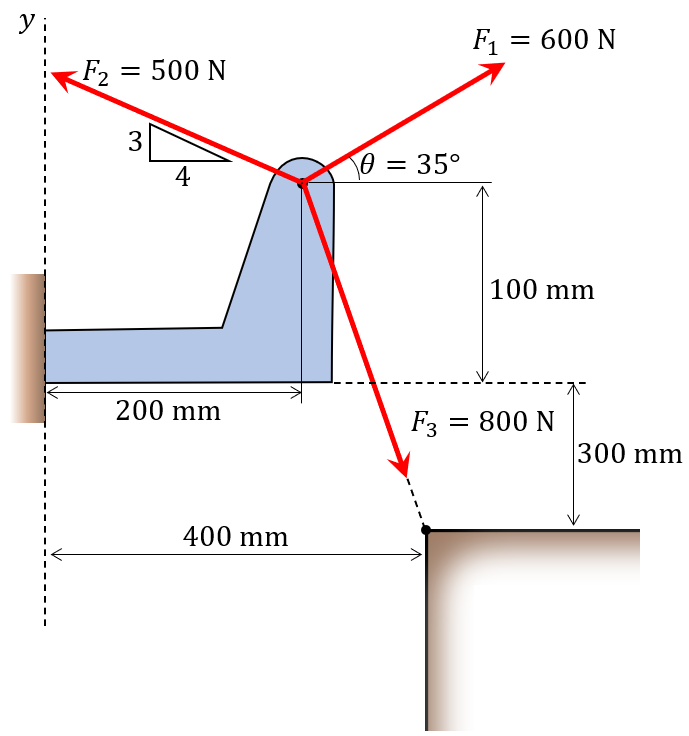
Do the following:
- Define the force vectors \(\mathbb{F}_1\), \(\mathbb{F}_2\), and \(\mathbb{F}_3\).
- Create a plot:
- draw the origin, point A, and point B with both markers and text.
- plot the force vectors
- Calculate and plot the resultant vector \(\mathbb{R}\).
Paperwork
Code
Input the force magnitudes.
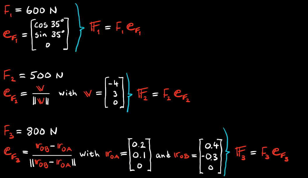
We shall define these as vectors. For \(\mathbb{F}_1\) we define it with the angle \(\theta = 35^\circ\). Its direction will then be \(\mathbb{e}_{F_1}=[\cos 35^\circ, \sin 35^\circ, 0]^\mathsf{T}\) and the magnitude is \(F_1=600\). Then, \[ \mathbb{F}_1=F_1 \mathbb{e}_{F_1} \]
# FF_1
theta = 35 * sp.pi/180 # Convert to radians

# Unit vector or directional vector for FF_1
ee_F1 = sp.Matrix([sp.cos(theta), sp.sin(theta), 0])
# Multiply the direction with the magnitude
FF_1 = F_1 * ee_F1

FF_1
\(\displaystyle \left[\begin{matrix}600 \cos{\left(\frac{7 \pi}{36} \right)}\\600 \sin{\left(\frac{7 \pi}{36} \right)}\\0\end{matrix}\right]\)
For \(\mathbb{F}_2\) we could have introduced an angle, but this is not necessary and should be avoided!
Instead we define the vector \(\mathbb{v}=[-4, 3, 0]^\mathsf{T}\) and normalizing it (making it of unit length) by dividing with its magnitude with .normalize(). Which essentially becomes \[
\mathbb{e}_{F_2} = \frac{\mathbb{v}}{||\mathbb{v}||}
\] Then \[
\mathbb{F}_2=F_2 \mathbb{e}_{F_2}
\]
Code
# FF_2
# Create a unit vector from the slope indicated in the figure
ee_F2 = sp.Matrix([-4,3,0]).normalized()
FF_2 = F_2 * ee_F2 # Multiply the direction with the magnitude

FF_2
\(\displaystyle \left[\begin{matrix}-400\\300\\0\end{matrix}\right]\)
No we can define \(\mathbb{F}_3\) in a similar way by defining the vectors \(\mathbb{r}_{OA}=[0.2, 0.1, 0]^\mathsf{T}\) and \(\mathbb{r}_{OB}=[0.4, -0.3, 0]^\mathsf{T}\). Then \[ \mathbb{e}_{F_3} = \frac{\mathbb{r}_{OB}-\mathbb{r}_{OA}}{||\mathbb{r}_{OB}-\mathbb{r}_{OA}||} \] and \[ \mathbb{F}_3=F_3 \mathbb{e}_{F_3} \]
Code
# FF_3
rr_OA = sp.Matrix([0.2, 0.1, 0]) # Position vector for A
rr_OB = sp.Matrix([0.4, -0.3, 0]) # Position vector for B
rr_AB = rr_OB - rr_OA # Vector AB defined by "head-minus-tail"

ee_F3 = rr_AB.normalized()
FF_3 = F_3 * ee_F3 # Multiply the direction with the magnitude

FF_3
\(\displaystyle \left[\begin{matrix}357.770876399966\\-715.541752799933\\0\end{matrix}\right]\)
To calculate the resultant force \(\mathbb{R}=\sum \mathbb{F}_i=\mathbb{F}_1+\mathbb{F}_2+\mathbb{F}_3\)
Code
# RR
RR = FF_1 + FF_2 + FF_3 # Resultant by adding the force vectors

RR
\(\displaystyle \left[\begin{matrix}-42.2291236000336 + 600 \cos{\left(\frac{7 \pi}{36} \right)}\\-415.541752799933 + 600 \sin{\left(\frac{7 \pi}{36} \right)}\\0\end{matrix}\right]\)
And its magnitude, \(R=||\mathbb{R}||\) is calculated with .norm(). The addition of evalf() is to make it into a decimal number.
Code
# R
R = RR.norm().evalf() # Magnitude of the resultant as a decimal number

R
\(\displaystyle 454.899780631079\)
Visualization
Finally, we plot the situation.
Show the code
### Plotting the vectors and points
rr_O = np.array([0, 0, 0])
offset = 0.01

# Create a plot and make settings
plt.style.use('seaborn-v0_8-whitegrid')
fig = plt.figure(figsize=(6, 6))
ax = fig.add_subplot()
ax.set(xlim=[-0.2, 0.8], ylim=[-0.5, 0.5], xlabel='X [m]', ylabel='Y [m]')
ax.set_title("Force vectors and resultants")
plt.grid(True, which='both', color='k', linestyle='-', alpha=0.1)
plt.minorticks_on()

# Create the points O, A, and B with text
ax.plot(rr_O[0],rr_O[1], 'ok', ms=5)
ax.text(rr_O[0]+offset,rr_O[1]+offset,"O")

ax.plot(rr_OA[0], rr_OA[1], 'ob', ms=5)
ax.text(rr_OA[0]+offset, rr_OA[1]+offset,"A")

ax.plot(rr_OB[0], rr_OB[1], 'ob', ms=5)
ax.text(rr_OB[0]+offset, rr_OB[1]+offset,"B")

# Create the dashed line from A to B
ax.plot(*zip(rr_OA[:-1],rr_OB[:-1]),'--k', zorder=0)

# Create vectors with numeric values
rr_OA_np = np.array(rr_OA).astype(np.float64)
rr_OB_np = np.array(rr_OB).astype(np.float64)
FF_1_np = np.array(FF_1).astype(np.float64)
FF_2_np = np.array(FF_2).astype(np.float64)
FF_3_np = np.array(FF_3).astype(np.float64)
RR_np = np.array(RR).astype(np.float64)

# Create the vector arrows
ax.quiver(*rr_OA_np[:-1], *FF_1_np[:-1], color='orange', scale=3000, label="$\\mathbb{F}_1$")
ax.quiver(*rr_OA_np[:-1], *FF_2_np[:-1], color='blue', scale=3000, label="$\\mathbb{F}_2$")
ax.quiver(*rr_OA_np[:-1], *FF_3_np[:-1], color='red', scale=3000, label="$\\mathbb{F}_3$")
ax.quiver(*rr_OA_np[:-1], *RR_np[:-1], color='green', scale=3000, label="$\\mathbb{R}$")

ax.legend()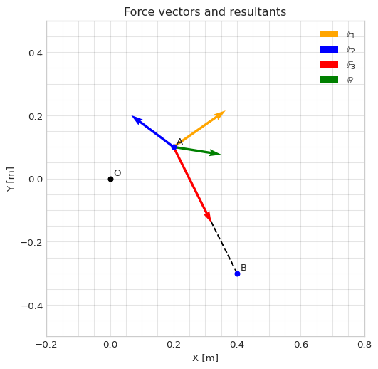
Force vectors: Example 2
Problem
These are the most typical types of forces that can appear in the wild.
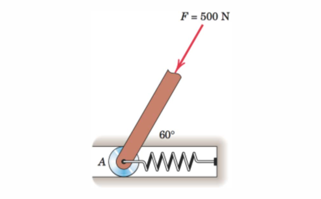
Do the following:
- Define the force vectors \(\mathbb{F}\), and the force in the spring, \(\mathbb{F}_s\).
- Calulate the magnitude, \(F_s\), so that the resultant \(\mathbb{R}\) is vertical and determine its magnitude \(R\).
- Create a plot of the vectors.
Code
Input the force magnitude.
# Magnitude of the force
F = 500
We shall define the vectors. For \(\mathbb{F}\) we define it with the angle \(\theta = 60^\circ\). Its direction will then be \(\mathbb{e}_{F}=[-\cos 60^\circ, -\sin 60^\circ, 0]^\mathsf{T}\) and the magnitude is \(F=500\). Then, \[ \mathbb{F}=F \mathbb{e}_{F} \]
# FF
theta = 60 * sp.pi/180 # Convert to radians

# Unit vector or directional vector for FF
ee_F = sp.Matrix([-sp.cos(theta), -sp.sin(theta), 0])
# Multiply the direction with the magnitude
FF = F * ee_F

FF
\(\displaystyle \left[\begin{matrix}-250\\- 250 \sqrt{3}\\0\end{matrix}\right]\)
For \(\mathbb{F}_s\) we know the direction is along the x-axis but the magnitude is unknown. So, we define it using \(\mathbb{e}_{F_s}=[1, 0, 0]^\mathsf{T}\) and \(F_s\). \[ \mathbb{F}_s=F_s \mathbb{e}_{F_s} \]
Code
# FF_s
F_s = sp.symbols('F_s', real=True) # Symbolic variable for the magnitude of FF_s
ee_Fs = sp.Matrix([1,0,0]) # Create a unit vector in positive x-direction
FF_s = F_s * ee_Fs # Multiply the direction with the magnitude

FF_s
\(\displaystyle \left[\begin{matrix}F_{s}\\0\\0\end{matrix}\right]\)
For \(\mathbb{R}\) we know the direction is along the y-axis but the magnitude is unknown. So, we define it using \(\mathbb{e}_{R}=[0, -1, 0]^\mathsf{T}\) and \(R\). \[ \mathbb{R}=R \mathbb{e}_{R} \]
Code
# RR
R = sp.symbols('R', real=True) # Define a symbolic variable as the magnitude of RR
ee_R = sp.Matrix([0,-1,0]) # Create a unit vector in negative y-direction
RR = R * ee_R # Multiply the direction with the magnitude

RR
\(\displaystyle \left[\begin{matrix}0\\- R\\0\end{matrix}\right]\)
The resultant \(\mathbb{R}\) is calculated with: \[ \mathbb{R}=\mathbb{F}+\mathbb{F}_s \] and we get \[ \begin{align} \begin{bmatrix} 0 \\ -R \\ 0 \end{bmatrix} = \begin{bmatrix} -250 \\ -250\sqrt{3} \\ 0 \end{bmatrix} + \begin{bmatrix} F_s \\ 0 \\ 0 \end{bmatrix} \end{align} \]
Code
# Solve for the unknown variables
eqn = sp.Eq(FF+FF_s, RR) # Define a system of equations
sol = sp.solve(eqn,[R,F_s]) # Solve for the unknowns

sol
{F_s: 250, R: 250*sqrt(3)}Thus we have the following numerical values for \(R\) and \(F_s\).
Code
sol[R].evalf() # Magnitude of the resultant R as a decimal number\(\displaystyle 433.012701892219\)
Code
sol[F_s].evalf() # Magnitude of the spring force F_s as a decimal number\(\displaystyle 250.0\)
Visualization
Finally, we plot the situation.
Show the code
### Plotting the vectors and points
rr_O = np.array([0, 0, 0])
offset = 0.01

# Create a plot and make settings
plt.style.use('seaborn-v0_8-whitegrid')
fig = plt.figure(figsize=(6, 6))
ax = fig.add_subplot()
ax.set(xlim=[-0.5, 0.5], ylim=[-0.5, 0.5], xlabel='X [m]', ylabel='Y [m]')
ax.set_title("Force vectors and resultants")
plt.grid(True, which='both', color='k', linestyle='-', alpha=0.1)
plt.minorticks_on()

# Create the point O with text
ax.plot(*zip(rr_O), 'ok', ms=5)
ax.text(rr_O[0]+offset,rr_O[1]+offset,"A")

# Create vectors with numeric values
FF_np = np.array(FF).astype(np.float64)
FF_s_np = np.array(FF_s.subs(F_s,sol[F_s])).astype(np.float64)
RR_np = np.array(RR.subs(R,sol[R])).astype(np.float64)

# Create the vector arrows
ax.quiver(*rr_O[:-1], *FF_np[:-1], color='orange', scale=1000, label="$\\mathbb{F}$")
ax.quiver(*rr_O[:-1], *FF_s_np[:-1], color='blue', scale=1000, label="$\\mathbb{F}_s$")
ax.quiver(*rr_O[:-1], *RR_np[:-1], color='green', scale=1000, label="$\\mathbb{R}$")

ax.legend()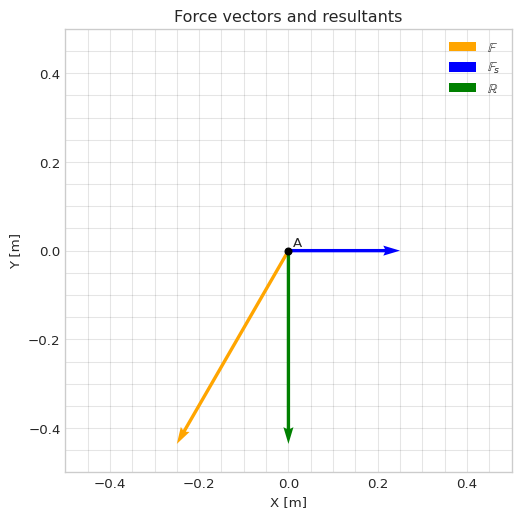
Force vectors: Example 3
Problem
These are the most typical types of forces that can appear in the wild.
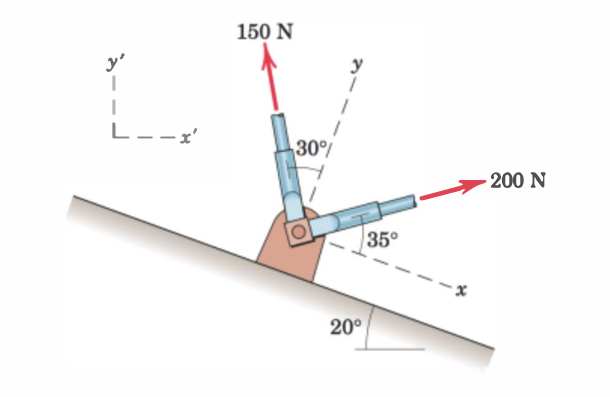
Do the following:
- Define the force vectors \(\mathbb{F}_1\) and \(\mathbb{F}_2\).
- Calulate the resultant \(\mathbb{R}\).
- Define \(\mathbb{R}\) in terms of the xy-base.
- Create a plot of the vectors.
Code
Input the force magnitudes.
# Magnitudes of the forces
F_1 = 200 # [N]
F_2 = 150 # [N]
Before we can define the actual force vectors we define the basis vectors \(\mathbb{e}_x\), \(\mathbb{e}_y\), and \(\mathbb{e}_z\) that make up the xy-base. The xy-base has an angle of \(\theta_1=20^\circ\).
Code
# Define the basis vectors for the xy-base
theta_1 = 20 * sp.pi/180 # Convert to radians

ee_x = sp.Matrix([sp.cos(theta_1), -sp.sin(theta_1), 0])
ee_y = sp.Matrix([sp.sin(theta_1), sp.cos(theta_1), 0])
ee_z = sp.Matrix([0, 0, 1])
We shall now define the force vectors. For \(\mathbb{F}_1\) we define it with the angle \(\theta_2 = 35^\circ\) in the xy-base. Its direction will then be
\[ \mathbb{e}_{F_1}=\mathbb{e}_x \cos \theta_2 + \mathbb{e}_y \sin \theta_2 + 0 \mathbb{e}_z \]
and the magnitude is \(F_1=200\) N. Then,
\[ \mathbb{F}_1 = F_1 \mathbb{e}_{F_1} \]
# FF_1
theta_2 = 35* sp.pi/180 # Convert to radians

# Unit vector or directional vector for FF_1
ee_F1 = ee_x*sp.cos(theta_2) + ee_y*sp.sin(theta_2)
FF_1 = F_1 * ee_F1 # Multiply the direction with the magnitude

FF_1
\(\displaystyle \left[\begin{matrix}200 \sin{\left(\frac{\pi}{9} \right)} \sin{\left(\frac{7 \pi}{36} \right)} + 200 \cos{\left(\frac{\pi}{9} \right)} \cos{\left(\frac{7 \pi}{36} \right)}\\- 200 \sin{\left(\frac{\pi}{9} \right)} \cos{\left(\frac{7 \pi}{36} \right)} + 200 \sin{\left(\frac{7 \pi}{36} \right)} \cos{\left(\frac{\pi}{9} \right)}\\0\end{matrix}\right]\)
For \(\mathbb{F}_2\) we define it with the angle \(\theta_3 = 30^\circ\) in the xy-base. Its direction will then be
\[ \mathbb{e}_{F_2}=\mathbb{e}_x (-\sin \theta_3) + \mathbb{e}_y \cos \theta_3 + 0 \mathbb{e}_z \]
and the magnitude is \(F_2=150\) N. Then,
\[ \mathbb{F}_2 = F_2 \mathbb{e}_{F_2} \]
Code
# FF_2
theta_3 = 30 * sp.pi/180 # Convert to radians

# Unit vector or directional vector for FF_2
ee_F2 = ee_x*(-sp.sin(theta_3)) + ee_y*sp.cos(theta_3)
FF_2 = F_2 * ee_F2 # Multiply the direction with the magnitude

FF_2
\(\displaystyle \left[\begin{matrix}- 75 \cos{\left(\frac{\pi}{9} \right)} + 75 \sqrt{3} \sin{\left(\frac{\pi}{9} \right)}\\75 \sin{\left(\frac{\pi}{9} \right)} + 75 \sqrt{3} \cos{\left(\frac{\pi}{9} \right)}\\0\end{matrix}\right]\)
We have now defined \(\mathbb{F}_1\) and \(\mathbb{F}_2\) utilizing the xy-base, but the vector components are in terms of the x’y’-base. To calculate \(\mathbb{R}\) we can now add \(\mathbb{F}_1\) and \(\mathbb{F}_2\). \[ \mathbb{R}=\mathbb{F}_1 + \mathbb{F}_2 \]
Code
# RR in the x'y'-base
RR = FF_1 + FF_2 # Resultant by adding the force vectors

RR = sp.simplify(RR)
RR
\(\displaystyle \left[\begin{matrix}- 150 \sin{\left(\frac{\pi}{18} \right)} + 50 \sqrt{2} + 50 \sqrt{6}\\- 50 \sqrt{2} + 50 \sqrt{6} + 150 \cos{\left(\frac{\pi}{18} \right)}\\0\end{matrix}\right]\)
To express \(\mathbb{R}\) in the xy-base we can utilize our knowledge about transformations from linear algebra. The basis vectors of the xy-base can be used to construct the transformation matrix \(\mathbb{A}\) that we can use to transform from the xy-base to the x’y’-base.
\[ \mathbb{A} = \begin{bmatrix} \vdots & \vdots & \vdots\\ \mathbb{e}_x & \mathbb{e}_y & \mathbb{e}_z \\ \vdots & \vdots & \vdots \end{bmatrix} \]
To transform in the opposite direction we can use \(\mathbb{A}^{-1}\). So \(\mathbb{R}_{xy}\) can be calculated with
\[ \mathbb{R}_{xy}=\mathbb{A}^{-1}\mathbb{R} \]
Code
# RR in the xy-base

# Transformation matrix with the xy-base vectors
transform = sp.Matrix.hstack(ee_x,ee_y,ee_z)

RR_xy = transform**-1 @ RR
RR_xy = sp.simplify(RR_xy)
RR_xy
\(\displaystyle \left[\begin{matrix}-75 + 200 \sin{\left(\frac{11 \pi}{36} \right)}\\200 \sin{\left(\frac{7 \pi}{36} \right)} + 75 \sqrt{3}\\0\end{matrix}\right]\)
Visualization
Finally, we plot the situation.
Show the code
### Plotting the vectors and points
rr_O = np.array([0, 0, 0])
offset = 0.05

# Create a plot and make settings
plt.style.use('seaborn-v0_8-whitegrid')
fig = plt.figure(figsize=(6, 6))
ax = fig.add_subplot()
ax.set(xlim=[-0.5, 0.5], ylim=[-0.5, 0.5], xlabel='X [m]', ylabel='Y [m]')
ax.set_title("Force vectors and resultants")
plt.grid(True, which='both', color='k', linestyle='-', alpha=0.1)
plt.minorticks_on()


# Create the point O with text
ax.plot(*zip(rr_O), 'ok', ms=5)


# Create the coordinate systems
ee_x_np = np.array(ee_x).astype(np.float64).flatten()
ee_y_np = np.array(ee_y).astype(np.float64).flatten()

ax.plot([-0.2, -0.3, -0.3], [0, 0, 0.1], linestyle='--', color='black', dashes=(10, 10), marker='.', linewidth=0.6)
ax.text(-0.3-offset,0-offset,"x'y'-base")

ax.plot(*zip(0.1*ee_x_np[:-1], rr_O[:-1], 0.1*ee_y_np[:-1]), linestyle='--', color='black', dashes=(10, 10), marker='.', linewidth=0.6)
ax.text(rr_O[0]-offset,rr_O[1]-offset,"xy-base")


# Create vectors with numeric values
FF_1_np = np.array(FF_1).astype(np.float64)
FF_2_np = np.array(FF_2).astype(np.float64)
RR_np = np.array(RR).astype(np.float64)


# Create the vector arrows
ax.quiver(*rr_O[:-1], *FF_1_np[:-1], color='orange', scale=1000, label="$\\mathbb{F}_1$")
ax.quiver(*rr_O[:-1], *FF_2_np[:-1], color='blue', scale=1000, label="$\\mathbb{F}_2$")
ax.quiver(*rr_O[:-1], *RR_np[:-1], color='green', scale=1000, label="$\\mathbb{R}$")

ax.legend()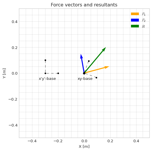
Force vectors: Example 4
Problem
These are the most typical types of forces that can appear in the wild.
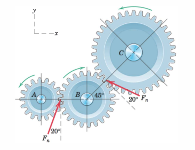
Do the following:
- Define the force vectors \(\mathbb{F}_1\), and \(\mathbb{F}_2\).
- Calulate the resultant \(\mathbb{R}\).
- Create a plot of the vectors.
Code
Input the force magnitudes.
# Magnitude of the force
F_n = 5500
We shall define these as vectors. For \(\mathbb{F}_1\) we define it with the angle \(\theta_1 = 20^\circ\). Its direction will then be \(\mathbb{e}_{F_1}=[\sin 20^\circ, \cos 20^\circ, 0]^\mathsf{T}\) and the magnitude is \(F_n=5500\). Then, \[ \mathbb{F}_1=F_n \mathbb{e}_{F_1} \]
# FF_1
theta_1 = 20 * sp.pi/180 # Convert to radians

# Unit vector or directional vector for FF_1
ee_F1 = sp.Matrix([sp.sin(theta_1), sp.cos(theta_1), 0])
FF_1 = F_n * ee_F1 # Multiply the direction with the magnitude

FF_1
\(\displaystyle \left[\begin{matrix}5500 \sin{\left(\frac{\pi}{9} \right)}\\5500 \cos{\left(\frac{\pi}{9} \right)}\\0\end{matrix}\right]\)
For \(\mathbb{F}_2\) we define it with the angle \(\theta_2 = (45+90+20)^\circ\). Its direction will then be \(\mathbb{e}_{F_2}=[\cos \theta_2, \sin \theta_2, 0]^\mathsf{T}\) and the magnitude is \(F_n=5500\). Then, \[ \mathbb{F}_2=F_n \mathbb{e}_{F_2} \]
Code
# FF_2
theta_2 = (45+90+20) * sp.pi/180 # Convert to radians

# Unit vector or directional vector for FF_2
ee_F2 = sp.Matrix([sp.cos(theta_2), sp.sin(theta_2), 0])
FF_2 = F_n * ee_F2 # Multiply the direction with the magnitude

FF_2
\(\displaystyle \left[\begin{matrix}- 5500 \cos{\left(\frac{5 \pi}{36} \right)}\\5500 \sin{\left(\frac{5 \pi}{36} \right)}\\0\end{matrix}\right]\)
To calculate the resultant force \(\mathbb{R}=\sum \mathbb{F}_i=\mathbb{F}_1+\mathbb{F}_2\)
Code
RR = FF_1 + FF_2 # Resultant by adding the force vectors

RR
\(\displaystyle \left[\begin{matrix}- 5500 \cos{\left(\frac{5 \pi}{36} \right)} + 5500 \sin{\left(\frac{\pi}{9} \right)}\\5500 \sin{\left(\frac{5 \pi}{36} \right)} + 5500 \cos{\left(\frac{\pi}{9} \right)}\\0\end{matrix}\right]\)
Visualization
Finally, we plot the situation.
Show the code
### Plotting the vectors and points
rr_O = np.array([0, 0, 0])
offset = 0.01

# Create a plot and make settings
plt.style.use('seaborn-v0_8-whitegrid')
fig = plt.figure(figsize=(6, 6))
ax = fig.add_subplot()
ax.set(xlim=[-0.5, 0.5], ylim=[-0.5, 0.5], xlabel='X [m]', ylabel='Y [m]')
ax.set_title("Force vectors and resultants")
plt.grid(True, which='both', color='k', linestyle='-', alpha=0.1)
plt.minorticks_on()

# Create the point O with text
ax.plot(*zip(rr_O), 'ok', ms=5)
ax.text(rr_O[0]+offset,rr_O[1]+offset,"B")

# Create vectors with numeric values
FF_1_np = np.array(FF_1).astype(np.float64)
FF_2_np = np.array(FF_2).astype(np.float64)
RR_np = np.array(RR).astype(np.float64)

# Create the vector arrows
ax.quiver(*rr_O[:-1], *FF_1_np[:-1], color='orange', scale=20000, label="$\\mathbb{F}_1$", pivot='tip')
ax.quiver(*rr_O[:-1], *FF_2_np[:-1], color='blue', scale=20000, label="$\\mathbb{F}_2$", pivot='tip')
ax.quiver(*rr_O[:-1], *RR_np[:-1], color='green', scale=20000, label="$\\mathbb{R}$")

ax.legend()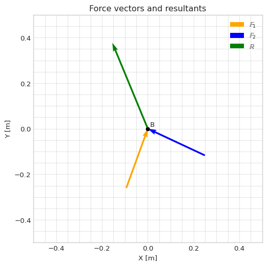
Force vectors: Example 5
Problem
These are the most typical types of forces that can appear in the wild.
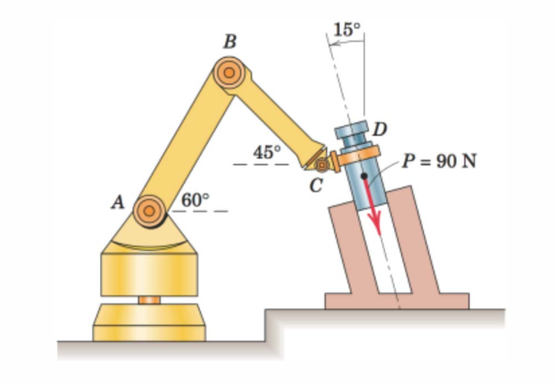
Do the following:
- Define the force vector \(\mathbb{P}\).
- Determine the force parallel and perpendicular to AB.
- Determine the force parallel and perpendicular to BC.
- Create a plot to visualize the vectors.
Code
Input the force magnitude.
# Magnitude of the force
P = 90 # [N]
For \(\mathbb{P}\) we define it with the angle \(\theta_1 = 15^\circ\). Its direction will then be \(\mathbb{e}_{P}=[\sin 15^\circ, -\cos 15^\circ, 0]^\mathsf{T}\) and the magnitude is \(P=90\) N. Then,
\[ \mathbb{P}=P \mathbb{e}_{P} \]
Code
# PP
theta_1 = 15* sp.pi/180 # Convert to radians

# Unit vector or directional vector for PP
ee_P = sp.Matrix([sp.sin(theta_1), -sp.cos(theta_1), 0])
PP = P * ee_P # Multiply the direction with the magnitude

PP
\(\displaystyle \left[\begin{matrix}- \frac{45 \sqrt{2}}{2} + \frac{45 \sqrt{6}}{2}\\- \frac{45 \sqrt{6}}{2} - \frac{45 \sqrt{2}}{2}\\0\end{matrix}\right]\)
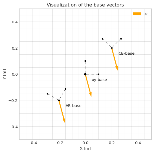
We define the basis vectors for the AB-arm as \(\mathbb{e}_{AB\parallel}\), and \(\mathbb{e}_{AB\perp}\) (that is rotated \(90^\circ\) relative to \(\mathbb{e}_{AB\parallel}\)). The AB-arm is defined with an angle of \(\theta_2=60^\circ\). The two vectors can then be written as \[ \mathbb{e}_{AB\parallel} = \begin{bmatrix} \cos \theta_2\\ \sin \theta_2\\ 0 \end{bmatrix} \]
and
\[ \mathbb{e}_{AB\perp} = \begin{bmatrix} -\sin \theta_2\\ \cos \theta_2\\ 0 \end{bmatrix} \]
Code
# Define the basis vectors for the arm AB
theta_2 = 60 * sp.pi/180 # Convert to radians

ee_ABpar = sp.Matrix([sp.cos(theta_2), sp.sin(theta_2), 0])
ee_ABperp = sp.Matrix([-sp.sin(theta_2), sp.cos(theta_2), 0])
Then, we define the basis vectors for the CB-arm as \(\mathbb{e}_{CB\parallel}\), and \(\mathbb{e}_{CB\perp}\) (that is rotated \(90^\circ\) relative to \(\mathbb{e}_{CB\parallel}\)). The CB-arm is defined with an angle of \(\theta_3=45^\circ\). The two vectors can then be written as \[ \mathbb{e}_{CB\parallel} = \begin{bmatrix} -\cos \theta_2\\ \sin \theta_2\\ 0 \end{bmatrix} \]
and
\[ \mathbb{e}_{CB\perp} = \begin{bmatrix} \sin \theta_2\\ \cos \theta_2\\ 0 \end{bmatrix} \]
# Define the basis vectors for the arm CB
theta_3 = 45 * sp.pi/180 # Convert to radians

ee_CBpar = sp.Matrix([-sp.cos(theta_3), sp.sin(theta_3), 0])
ee_CBperp = sp.Matrix([sp.sin(theta_3), sp.cos(theta_3), 0])
To determine the amount of force along the different directions we defined, all we have to do is to utilize the dot-product. Since the directions are defined with vectors of unit length, computing the dot-prodoct between \(\mathbb{P}\) and the respective direction will give us the magnitude of force in that direction.
Code
# Determine the force in different directions of the arms

# The AB-arm
F_ABpar = sp.simplify(PP.dot(ee_ABpar))
F_ABperp = sp.simplify(PP.dot(ee_ABperp))

F_ABpar, F_ABperp
(-45*sqrt(2), -45*sqrt(2))And,
Code
# Determine the force in different directions of the arms

# The CB-arm
F_CBpar = sp.simplify(PP.dot(ee_CBpar))
F_CBperp = sp.simplify(PP.dot(ee_CBperp))

F_CBpar, F_CBperp
(-45*sqrt(3), -45)Visualization
Finally, we plot the situation.
Show the code
### Plotting the vectors and points
rr_O = np.array([0, 0, 0])
offset = 0.05

# Create a plot and make settings
plt.style.use('seaborn-v0_8-whitegrid')
fig = plt.figure(figsize=(6, 6))
ax = fig.add_subplot()
ax.set(xlim=[-0.5, 0.5], ylim=[-0.5, 0.5], xlabel='X [m]', ylabel='Y [m]')
ax.set_title("Visualization of the base vectors")
plt.grid(True, which='both', color='k', linestyle='-', alpha=0.1)
plt.minorticks_on()

# Create the point O with text
ax.plot(*zip(rr_O), 'ok', ms=5)

# Create the coordinate systems
ee_ABpar_np = np.array(ee_ABpar).astype(np.float64).flatten()
ee_ABperp_np = np.array(ee_ABperp).astype(np.float64).flatten()
ee_CBpar_np = np.array(ee_CBpar).astype(np.float64).flatten()
ee_CBperp_np = np.array(ee_CBperp).astype(np.float64).flatten()

ax.plot([0.1, 0, 0], [0, 0, 0.1], linestyle='--', color='black', dashes=(10, 10), marker='.', linewidth=0.6)
ax.text(0.05,0-offset,"xy-base")

ax.plot(*zip(0.1*ee_ABpar_np[:-1]-0.2, rr_O[:-1]-0.2, 0.1*ee_ABperp_np[:-1]-0.2), linestyle='--', color='black', dashes=(10, 10), marker='.', linewidth=0.6)
ax.text(rr_O[0]-0.15,rr_O[1]-offset-0.2,"AB-base")

ax.plot(*zip(0.1*ee_CBpar_np[:-1]+0.2, rr_O[:-1]+0.2, 0.1*ee_CBperp_np[:-1]+0.2), linestyle='--', color='black', dashes=(10, 10), marker='.', linewidth=0.6)
ax.text(rr_O[0]+0.25,rr_O[1]-offset+0.2,"CB-base")

# Create vectors with numeric values
PP_np = np.array(PP).astype(np.float64)

# Create the vector arrows
ax.quiver(*rr_O[:-1], *PP_np[:-1], color='orange', scale=500, label="$\\mathbb{P}$")
ax.quiver(*rr_O[:-1]+0.2, *PP_np[:-1], color='orange', scale=500)
ax.quiver(*rr_O[:-1]-0.2, *PP_np[:-1], color='orange', scale=500)

ax.legend()