10.3 H-Bridge Motor Driver
An H-bridge lets us drive a simple brushed DC motor in both directions from a single supply. The name comes from the four switches arranged in the shape of the letter H, with the motor sitting on the cross-bar. By closing different pairs of switches we steer current through the motor in either direction, giving us forward, reverse, coast and brake.
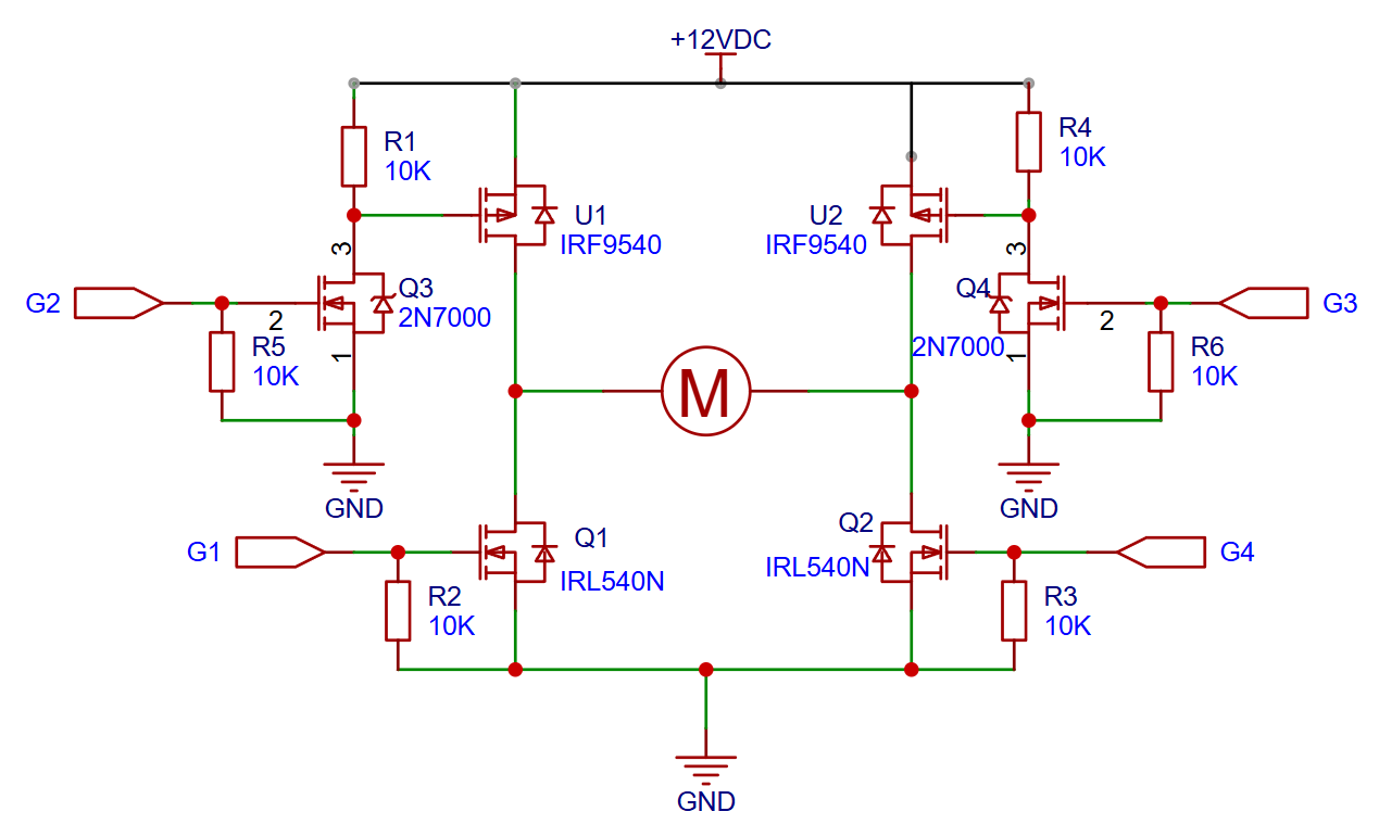
We build our bridge from two P-channel MOSFETs on the high side (IRF9540) and two N-channel MOSFETs on the low side (IRL540N). The IRL540N is a logic-level MOSFET: its gate threshold voltage is around 2 V, so the 3.3 V output of an ESP32 turns it on directly. The P-channel IRF9540 needs its gate pulled to ground to turn on, but its source sits at the supply voltage \(V_+\). A 3.3 V microcontroller cannot bridge that gap on its own, so we insert a 2N7000 as a level shifter on each high-side gate. When the ESP32 drives the 2N7000 on, it pulls the IRF9540 gate low; a 10 k\(\Omega\) pull-up resistor to \(V_+\) holds the IRF9540 off when the level shifter is not conducting.
The schematic below shows the full circuit.
The truth table below summarises the four operating modes. The G columns refer to the microcontroller output level; the resulting motor behaviour follows from which pair of MOSFETs conducts.
| G2 | G4 | G1 | G3 | Mode |
|---|---|---|---|---|
| HIGH | HIGH | LOW | LOW | Forward |
| LOW | LOW | HIGH | HIGH | Reverse |
| LOW | LOW | LOW | LOW | Coast |
| LOW | HIGH | HIGH | LOW | Brake |
In coast mode all four MOSFETs are off and the motor terminals are electrically disconnected from the supply. The rotor spins freely on its own inertia and slows down only through friction and back-EMF losses. In brake mode the two low-side MOSFETs (Q1 and Q2) are on while both high-side MOSFETs remain off. This shorts the motor terminals together through the ground rail. Any back-EMF the spinning rotor generates now drives current around that short loop, dissipating energy in the winding resistance and bringing the motor to a rapid stop.
Never turn on both MOSFETs on the same leg simultaneously (for example G2 and G1 both HIGH). That creates a shoot-through short from \(V_+\) to ground and will destroy the MOSFETs or the power supply. In software, insert a dead-time of at least 1 \(\mu\)s when switching directions: turn the active pair off, wait, then turn the new pair on.
For PWM speed control, apply the PWM signal to one of the low-side gate pins while holding the corresponding high-side pin HIGH. The motor sees the average voltage and runs at a proportional speed.
The interactive simulation below lets you toggle the switches and observe the current flow in real time.