5.2 Free body diagram
“To every Action there is always opposed an equal Reaction: or the mutual actions of two bodies upon each other are always equal, and directed to contrary parts.”
— Isaac Newton, Principia, Law III, 1687, translated by Andrew Motte, 1729
Modeling the action of forces using plane simplification.
Supports and reactions
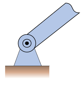
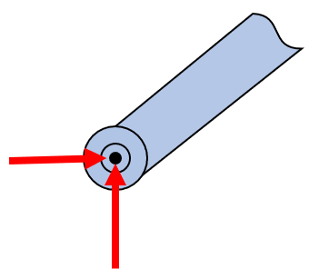
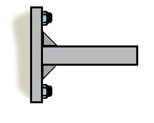
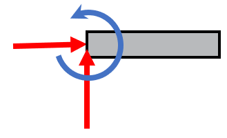
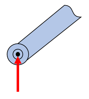
A body in the plane can move in three ways: it can slide sideways, slide up and down, and turn. A support blocks some of these motions, and for each motion it blocks it exerts one reaction component on the body. Along a motion it leaves free it exerts nothing. A pin blocks both slides and lets the body turn, so it gives two force components and no moment. A fixed support blocks all three motions and gives two force components and a moment.
The animations below show this for four supports. A free bar first shows its three motions in blue. Then the support arrives and each motion is tried again. A free motion still moves the bar. A blocked motion only makes the bar give a little before the support pushes back, and the push becomes the reaction, in red.
| Support | Blocks | Leaves free | Reactions | |
|---|---|---|---|---|
| roller | the slide across the surface | the slide along the surface and the turn | \(N\) | |
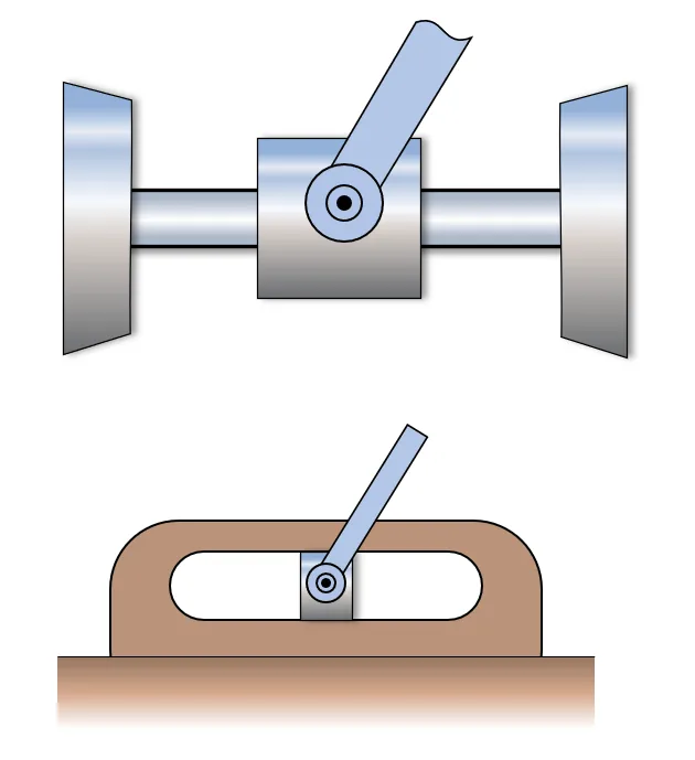
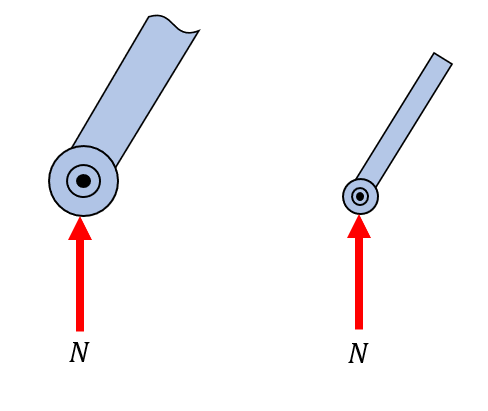
| collar on a guide rod | the slide across the rod | the slide along the rod and the turn | \(N\) | |
| pin | both slides | the turn | \(R_x\), \(R_y\) | |
| fixed support | both slides and the turn | nothing | \(R_x\), \(R_y\), \(M\) |
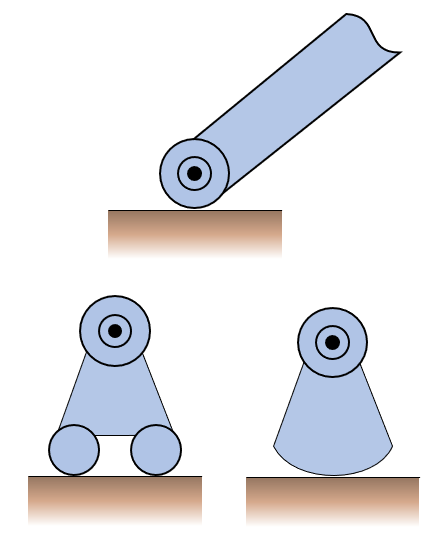
The roller and the collar block the same motion and therefore give the same reaction, a single force normal to the surface or the rod. The catalogue below lists the common supports with the reactions they give.
A force exerted by a flexible cable, belt, chain or rope is always a tensile force (away from the body) and cannot be negative (compressive) force.
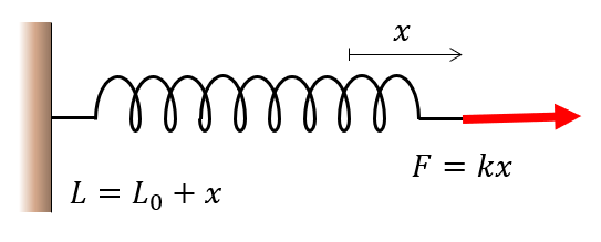
Springs have an unloaded length, \(L_0\), and upon loading, a displacement \(x\). As Figure 5.2.8 shows, the force is typically modeled as a linear relation
\[ F = k x \]
where \(k\) denotes the spring stiffness in Newtons per unit length, e.g., N/m.
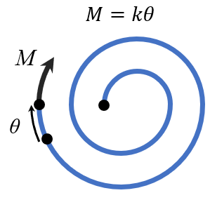
Torsional springs (Figure 5.2.9) are loaded by an external moment, \(M\) and the displacement, \(\theta\) can be measured in radians (typically) or degrees. The relationship between the torque and angular displacement is given by the linear model
\[ M = k \theta \]
where \(k\) is the torsional spring constant in Nm/rad or Nm/degree.
Supports in space
In space a body can move in six ways: it can slide along \(x\), \(y\) and \(z\) and turn about each of the three axes. The rule stays the same. A support exerts one force component for every slide it blocks and one moment for every turn it blocks, and nothing along a motion it leaves free. The table lists five common supports, each drawn in place on the left and freed on the right with its reactions.
| Support | Blocks | Leaves free | Reactions | |
|---|---|---|---|---|
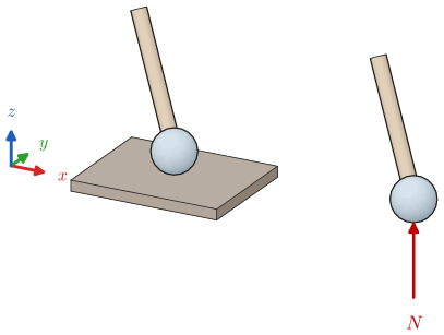 |
ball on a smooth surface | the slide normal to the surface | the two slides along the surface and all three turns | \(N\) |
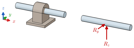 |
journal bearing, shaft along \(x\) | the slides along \(y\) and \(z\) | the slide along the shaft and the turns | \(R_y\), \(R_z\) |
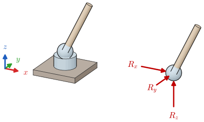 |
ball-and-socket joint | all three slides | all three turns | \(R_x\), \(R_y\), \(R_z\) |
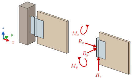 |
hinge, axis along \(z\) | all three slides and the turns about \(x\) and \(y\) | the turn about \(z\) | \(R_x\), \(R_y\), \(R_z\), \(M_x\), \(M_y\) |
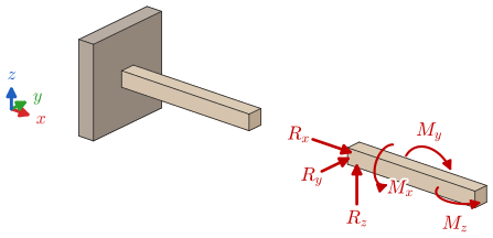 |
fixed support | all six motions | nothing | \(R_x\), \(R_y\), \(R_z\), \(M_x\), \(M_y\), \(M_z\) |
A short journal bearing lets the shaft tilt a little and is modelled with the two forces alone. A long bearing, or a single bearing that must hold the shaft on its own, also blocks the tilts about \(y\) and \(z\) and adds the moments \(M_y\) and \(M_z\). The same holds for hinges: a door hangs on two hinges, the pair blocks the tilts through their forces, and each hinge is then modelled with forces only.
Example 1
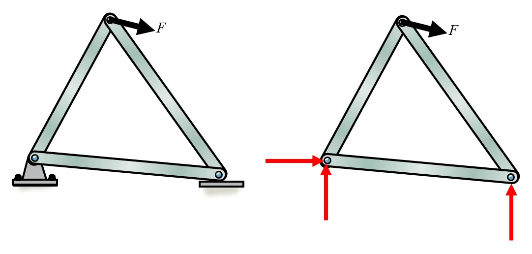
In Figure 5.2.10 the supports of the structure are replaced with reaction forces. On the left we have a pin support, that can carry forces in both \(x\) - and \(y\)-directions, while on the right side the structure is supported in the normal direction only. The normal force is perpendicular to the ground surface. It is important to model all supports with forces, the directions do not matter. For instance the left support is modelled with a force in the positive \(x\)-direction, while the external force clearly points to the right as well, meaning that once the equilibrium equations are solved, the reaction force will be negative, indicating the proper direction of this force in equilibrium.
Example 2
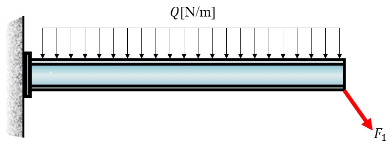
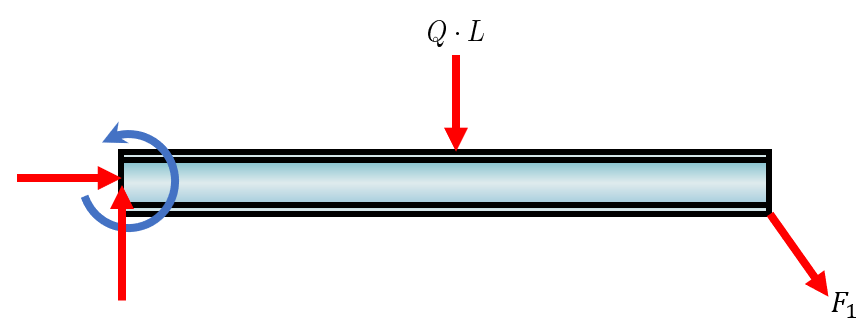
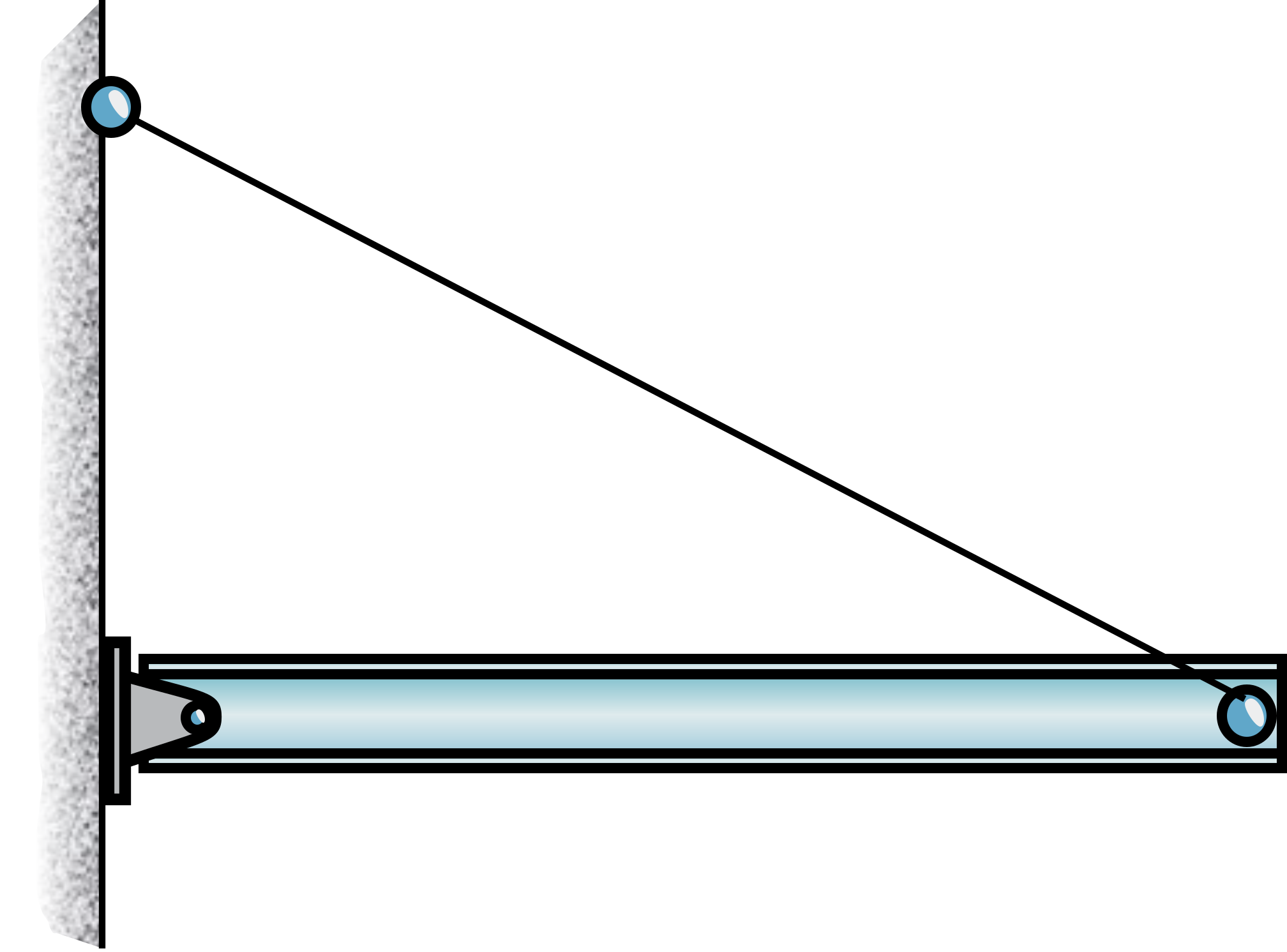
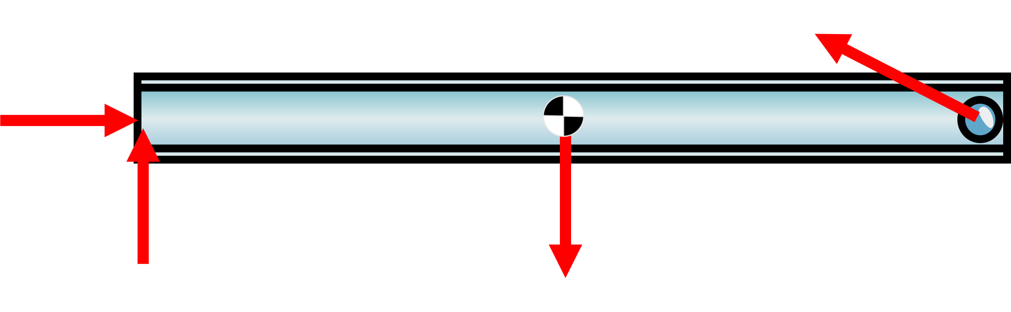
Here we have a rigid beam that is fixed to the wall, a so called cantilever beam. The supports of such beams carry both translational loads and rotation, i.e., moment.
There is a uniform load applied on the top, and Figure 5.2.12 shows how it enters the free body diagram. All distributed loads can be transformed into point loads acting on certain locations. The locations are calculated by finding the center of area and the loads are integrated. Our case is the simplest case of a distributed load, it can be transformed into a point load acting in the middle of the beam and the total load is \(F_{\text {tot }}=Q \cdot L\).
Example 3
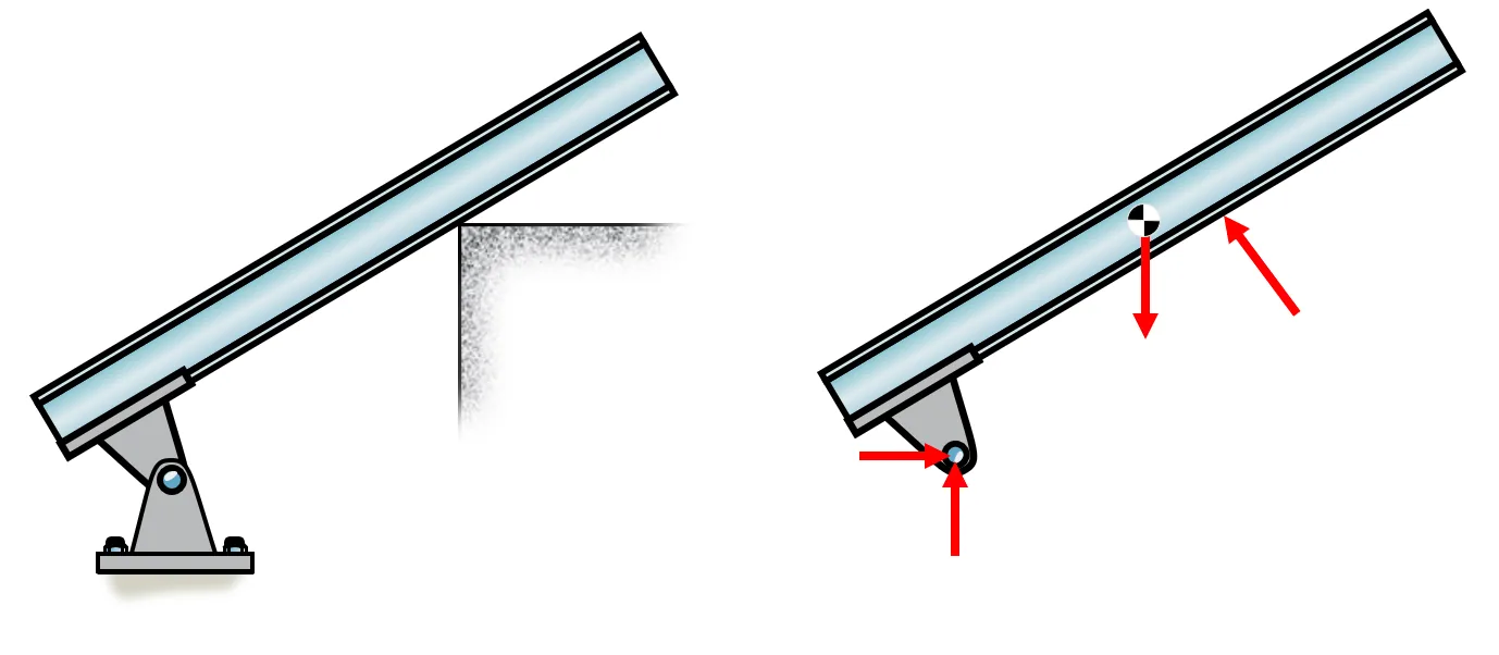
The beam in Figure 5.2.13 is resting on an edge, which in 2D is modelled as a normal force. The support is a pin support and the beam is assumed to have a uniform mass such that its center of gravity is in the middle, denoted by the center of gravity (COG) symbol. A bodies weight vector is acting on the COG.
Example 4
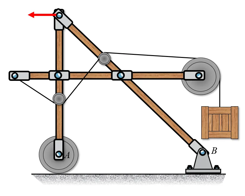
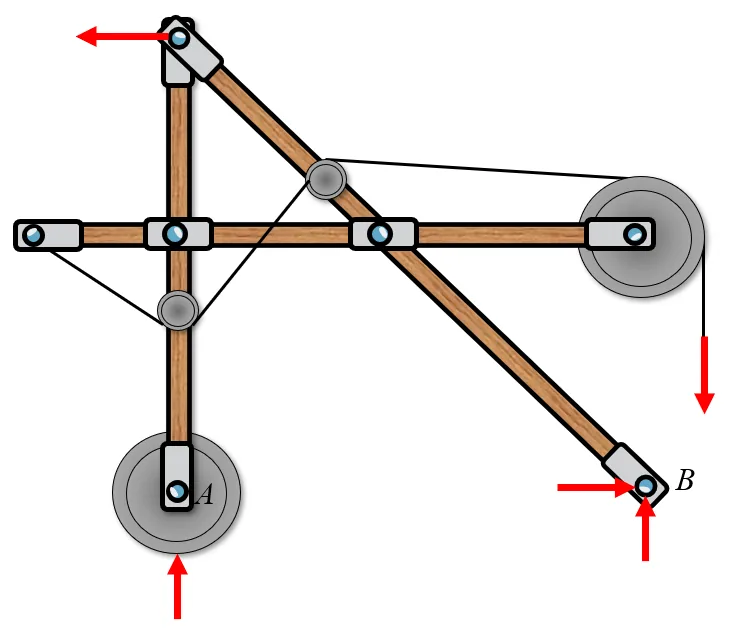
The structure in Figure 5.2.14 may seem complicated, but the external reaction forces are modelled on the whole structure. We have a sliding support on the left side and the pin support on the right. The weight of the box is modelled by a force vector.
Example 5: Multi-body system
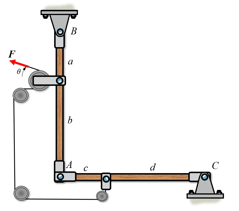
If we want to find all reaction forces, including the “internal” connector forces in point \(A\) we need to split the system in Figure 5.2.15 into its separate components, as marked in Figure 5.2.16.
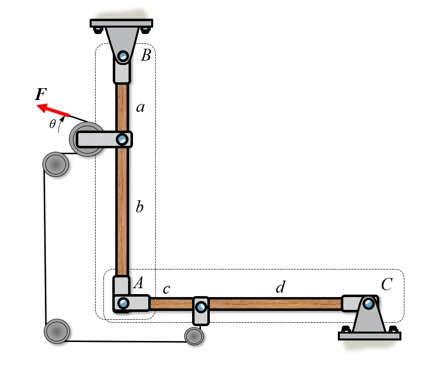
Here we have two systems, \(BA\) and \(AC\). Now we can create a free body diagram on each system separately. We assume that the rollers are frictionless such that the force \(F\) is translated without loss to body \(AC\).
We can insert reaction forces according to Figure 5.2.17 in the direction of our normal coordinate system. Special care must be taken at point \(A\) for the body \(AC\).
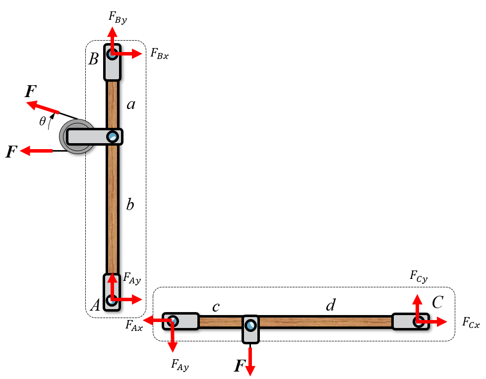
Although the direction of inserted reaction forces is not important for one body. We must ensure consistency in connection where several bodies meet. In this example at point \(A\) the inserted forces must cancel each other from both bodies. This means that for the body \(A C\) at point \(A\) we reverse the directions of the reaction forces compared to body \(B A\) at \(A\).
In cases where more than two bodies meet at a connector, the connecting rod itself needs to be isolated and a free body diagram established with a set of equilibrium equations!
Example 6: Three members at one pin
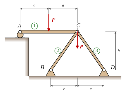
Three members meet at the pin \(C\) in Figure 5.2.18, and the load \(\bm P\) hangs from the pin itself. If we split the frame into its members only, we have to decide which member the pin belongs to, and with it which member carries \(\bm P\). We avoid that choice by isolating the pin as a fourth body, as in Figure 5.2.19.
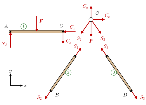
The legs 2 and 3 carry no load between their pins, so each is a two-force member and its force acts along it. We draw \(S_2\) and \(S_3\) as tension, pulling away from both ends of each leg, so on the pin they pull toward the legs. The beam carries \(\bm F\) between its ends and is no two-force member, so the pin acts on it with two components. We draw \(C_x\) and \(C_y\) positive on the pin and reversed on the beam, as at \(A\) in Example 5.
The unknowns are \(N_A\), \(C_x\), \(C_y\), \(S_2\) and \(S_3\). The beam gives three equilibrium equations and the pin two, since every force on the pin passes through its centre and the moment equation says nothing. Five equations for five unknowns, so the frame can be solved. The moment about \(A\) on the beam gives \(C_y = -F/2\): the beam presses down on the pin. The horizontal balance of the beam gives \(C_x = 0\), the horizontal balance of the pin then gives \(S_2 = S_3\), and the vertical balance of the pin gives
\[ S_2 = S_3 = -\frac{(P + F/2)\sqrt{h^2 + c^2}}{2h} \]
The minus sign tells us that both legs are in compression.