10.12 Hobby servos
The car steers with a hobby servo, a DS3218, that turns the steering linkage through a horn on its output shaft. A servo is a complete position controller in one housing: we send it a pulse that says where the shaft should be, and its own electronics drive the shaft there and hold it. This chapter first wires the servo to the car’s 7.0 V rail and the ESP32, uploads a small calibration program and finds the pulse widths that turn the wheels fully left and right without forcing the linkage against its stops. These end points go into platformio.ini, and the steering module written here is used unchanged in the complete car program. The explanation of the signal, the inside of the servo and the way the ESP32 generates the pulse comes after the guide.
The project folder is code/servo next to this chapter. It is built the way the PlatformIO chapter describes, so we assume that chapter is done.
The Guide
Step 1: Wire the servo
The servo takes its power from the 7.0 V rail made by the XL4015 buck converter, the same rail that feeds the ESP32 through its VIN pin. Only the signal wire goes to a GPIO pin. Figure 10.12.1 shows the circuit.
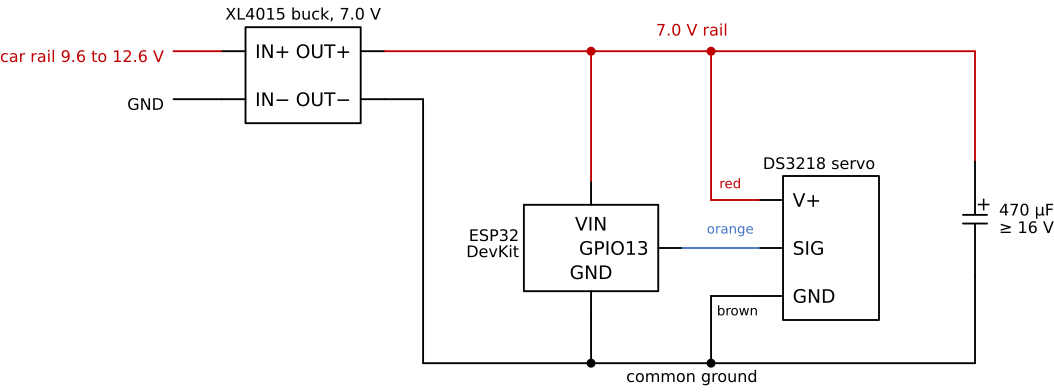
VIN). The 470 µF capacitor sits across the rail at the servo. GPIO 13 drives the signal wire, and every ground is joined.
Make the connections with the battery disconnected:
| From | To |
|---|---|
Buck OUT+ (7.0 V) |
Servo red wire, ESP32 VIN, capacitor + |
Buck OUT− |
Servo brown wire, ESP32 GND, capacitor − (stripe) |
ESP32 GPIO13 |
Servo orange wire (signal) |
The capacitor is a 470 µF electrolytic rated for at least 16 V. Solder or plug it in where the servo cable meets the rail, as close to the servo as the wiring allows. Its stripe marks the negative lead, and it must go to ground: an electrolytic capacitor connected backwards heats up and can vent. Check the wire colours against the table before power is applied.
Set the XL4015 to 7.0 V with nothing connected to its output and measure it with a multimeter. A buck converter left at its factory setting can put the full battery voltage, up to 12.6 V, on the servo and the ESP32, which destroys both within seconds.
The servos in our kits are labelled DC 4.8-7.4 V: they are made to run directly from a 2S LiPo at its nominal 7.4 V (2 × 3.7 V). The 7.0 V rail lies inside that range. A fully charged 2S pack gives 8.4 V, above the label, which is one more reason to feed the servo from the buck converter. Versions of the DS3218 are also sold labelled 4.8-6.8 V; read the label on yours, and set the rail no higher than the maximum printed there.
The ESP32 now runs from VIN. For calibration we also need the USB cable for the serial monitor, so for a while the board has two supplies at once.
VIN at the same time
On most ESP32 DevKit boards the USB 5 V reaches VIN through a diode. Without that diode, the buck converter and the computer’s USB port push current into each other. Check once: plug in only the USB cable and measure VIN against GND. About 4.4 to 4.8 V means a diode is present, and USB and the 7.0 V rail may be connected together (rail first, USB second). About 5.0 V means VIN is wired straight to USB; then never connect the rail while USB is plugged in.
Step 2: Create the project
Create a PlatformIO project called servo as in the PlatformIO chapter, and replace its platformio.ini with:
[env:esp32dev]
platform = espressif32@6.13.0
board = esp32dev
framework = arduino

upload_speed = 921600
monitor_speed = 115200
monitor_echo = yes
monitor_filters = send_on_enter, esp32_exception_decoder

build_flags =
    -D BAUD=${this.monitor_speed}
    ; servo signal: pin, LEDC channel, 50 Hz frame, 16-bit duty
    -D SERVO_PIN=13
    -D SERVO_CH=0
    -D SERVO_FREQ_HZ=50
    -D SERVO_RES_BITS=16
    ; steering end points in microseconds (replace after calibration)
    -D SERVO_LEFT_US=1000
    -D SERVO_CENTER_US=1500
    -D SERVO_RIGHT_US=2000
    ; hard limits: no pulse outside this window is ever sent
    -D SERVO_MIN_US=500
    -D SERVO_MAX_US=2500
Every number the program needs is a build flag. SERVO_PIN and SERVO_CH choose the pin and the PWM channel, SERVO_FREQ_HZ and SERVO_RES_BITS describe the signal, and the three end points are the pulse widths, in microseconds, that turn the wheels fully left, straight ahead and fully right. The defaults 1000, 1500 and 2000 µs turn the horn 45° each way from center, a safe start that our calibration will replace. SERVO_MIN_US and SERVO_MAX_US are hard limits: no pulse outside 500 to 2500 µs ever leaves the board, even when a command asks for one.
Create src/servo_control.h with the steering module:
// servo_control.h: steering servo on one LEDC channel (Arduino-ESP32 core 2 API).
//
// Settings come from build_flags in platformio.ini:
//   SERVO_PIN, SERVO_CH                 signal pin and LEDC channel
//   SERVO_FREQ_HZ, SERVO_RES_BITS       frame rate (50) and duty resolution (16)
//   SERVO_LEFT_US, SERVO_CENTER_US,
//   SERVO_RIGHT_US                      calibrated steering end points
//   SERVO_MIN_US, SERVO_MAX_US          hard limits for every pulse
//
// Use: servoBegin() once in setup(), then setSteering(-1.0 .. +1.0).
// LEDC channels share timers in pairs (0-1, 2-3, ...), so the other channel
// of the servo's pair must not be used at another frequency.
#pragma once
#include <Arduino.h>
#include <math.h>

#if !defined(SERVO_PIN) || !defined(SERVO_CH) || !defined(SERVO_FREQ_HZ) || \
    !defined(SERVO_RES_BITS)
#error "Set SERVO_PIN, SERVO_CH, SERVO_FREQ_HZ and SERVO_RES_BITS in build_flags"
#endif
#if !defined(SERVO_LEFT_US) || !defined(SERVO_CENTER_US) || \
    !defined(SERVO_RIGHT_US) || !defined(SERVO_MIN_US) || !defined(SERVO_MAX_US)
#error "Set SERVO_LEFT_US, SERVO_CENTER_US, SERVO_RIGHT_US, SERVO_MIN_US and SERVO_MAX_US in build_flags"
#endif

static_assert(SERVO_MIN_US < SERVO_MAX_US, "SERVO_MIN_US must be below SERVO_MAX_US");
static_assert(SERVO_LEFT_US >= SERVO_MIN_US && SERVO_LEFT_US <= SERVO_MAX_US,
              "SERVO_LEFT_US outside SERVO_MIN_US..SERVO_MAX_US");
static_assert(SERVO_RIGHT_US >= SERVO_MIN_US && SERVO_RIGHT_US <= SERVO_MAX_US,
              "SERVO_RIGHT_US outside SERVO_MIN_US..SERVO_MAX_US");
static_assert(SERVO_CENTER_US >= SERVO_MIN_US && SERVO_CENTER_US <= SERVO_MAX_US,
              "SERVO_CENTER_US outside SERVO_MIN_US..SERVO_MAX_US");

// Pulse width in microseconds to LEDC duty count, rounded to nearest:
// duty = us * 2^bits * freq / 1e6. The product reaches 8.2e9 for 2500 us at
// 50 Hz and 16 bits, beyond 32 bits, so it is formed in 64 bits.
inline uint32_t servoUsToDuty(uint32_t us) {
  uint64_t num = ((uint64_t)us << SERVO_RES_BITS) * SERVO_FREQ_HZ;
  return (uint32_t)((num + 500000ULL) / 1000000ULL);
}

// The pulse width last sent, in microseconds.
inline int &servoPulseUs() {
  static int us = SERVO_CENTER_US;
  return us;
}

// Send a raw pulse width, clamped to SERVO_MIN_US..SERVO_MAX_US.
// Returns the pulse width actually sent.
inline int servoWriteUs(int us) {
  us = constrain(us, SERVO_MIN_US, SERVO_MAX_US);
  ledcWrite(SERVO_CH, servoUsToDuty(us));
  servoPulseUs() = us;
  return us;
}

// Steering command to pulse width: -1 = SERVO_LEFT_US, 0 = SERVO_CENTER_US,
// +1 = SERVO_RIGHT_US, linear on each side. Works for left > right as well.
inline int servoSteeringToUs(float s) {
  if (isnan(s)) s = 0.0f;
  s = constrain(s, -1.0f, 1.0f);
  float end = (s < 0.0f) ? SERVO_LEFT_US : SERVO_RIGHT_US;
  float us = SERVO_CENTER_US + fabsf(s) * (end - SERVO_CENTER_US);
  return (int)lroundf(us);
}

// Steer: -1.0 full left, 0 straight ahead, +1.0 full right.
inline int setSteering(float s) {
  return servoWriteUs(servoSteeringToUs(s));
}

// Configure the LEDC channel and center the servo. Returns false if the
// channel could not be set up (frequency and resolution not possible).
inline bool servoBegin() {
  if (ledcSetup(SERVO_CH, SERVO_FREQ_HZ, SERVO_RES_BITS) == 0) return false;
  servoWriteUs(SERVO_CENTER_US);  // duty set before the pin is attached
  ledcAttachPin(SERVO_PIN, SERVO_CH);
  return true;
}
The car program later includes this same file. Its interface is three functions: servoBegin() sets up the PWM channel and centers the servo, setSteering(s) steers with a number from −1.0 (full left) through 0 (straight) to +1.0 (full right), and servoWriteUs(us) sends a raw pulse width, which only calibration needs.
Replace src/main.cpp with the calibration program:
#include <Arduino.h>
#include "servo_control.h"

// Steering calibration over the serial monitor. Commands (Enter to send):
//   us <n>   raw pulse width in microseconds, e.g. us 1500
//   + / -    step the pulse 10 us up / down
//   l c r    full left, center, full right (end points from build_flags)
//   s <x>    steering command -1.0 .. +1.0, e.g. s 0.5
//   ?        print the current pulse and the end points
//   h        help

#if !defined(BAUD)
#error "Set BAUD in build_flags"
#endif

const int STEP_US = 10;

void printPulse() {
  int us = servoPulseUs();
  Serial.printf("pulse = %d us   duty = %lu / %lu\n", us,
                (unsigned long)servoUsToDuty(us),
                (unsigned long)(1UL << SERVO_RES_BITS));
}

void printHelp() {
  Serial.println("us <n> | + | - | l | c | r | s <x> | ? | h");
}

void printState() {
  Serial.printf("end points: left %d  center %d  right %d us  (limits %d..%d)\n",
                SERVO_LEFT_US, SERVO_CENTER_US, SERVO_RIGHT_US,
                SERVO_MIN_US, SERVO_MAX_US);
  printPulse();
}

void handleLine(String line) {
  line.trim();
  if (line.length() == 0) return;

  int sp = line.indexOf(' ');
  String cmd = (sp < 0) ? line : line.substring(0, sp);
  String arg = (sp < 0) ? "" : line.substring(sp + 1);

  if (cmd == "us" && arg.length()) {
    servoWriteUs(arg.toInt());
  } else if (cmd == "+") {
    servoWriteUs(servoPulseUs() + STEP_US);
  } else if (cmd == "-") {
    servoWriteUs(servoPulseUs() - STEP_US);
  } else if (cmd == "l") {
    setSteering(-1.0f);
  } else if (cmd == "c") {
    setSteering(0.0f);
  } else if (cmd == "r") {
    setSteering(1.0f);
  } else if (cmd == "s" && arg.length()) {
    float s = arg.toFloat();
    Serial.printf("steering %.2f -> ", constrain(s, -1.0f, 1.0f));
    setSteering(s);
  } else if (cmd == "?") {
    printState();
    return;
  } else if (cmd == "h") {
    printHelp();
    return;
  } else {
    Serial.printf("unknown: '%s'  ", line.c_str());
    printHelp();
    return;
  }
  printPulse();
}

void setup() {
  Serial.begin(BAUD);
  if (!servoBegin()) {
    Serial.println("LEDC setup failed, check SERVO_FREQ_HZ and SERVO_RES_BITS");
  }
  delay(200);
  Serial.println("\nSteering calibration");
  printHelp();
  printState();
}

void loop() {
  static String buf;
  while (Serial.available()) {
    char c = Serial.read();
    if (c == '\n' || c == '\r') {
      if (buf.length()) handleLine(buf);
      buf = "";
    } else if (buf.length() < 32) {
      buf += c;
    }
  }
}
Build and upload with the BOOT button as before, then open the serial monitor. The servo moves to 1500 µs when the program starts, and the monitor shows:
Steering calibration
us <n> | + | - | l | c | r | s <x> | ? | h
end points: left 1000  center 1500  right 2000 us  (limits 500..2500)
pulse = 1500 us   duty = 4915 / 65536
Step 3: Calibrate the end points
Steering geometry limits how far the wheels can turn. When the servo asks for more than that, the linkage binds: the wheel knuckle is against its stop, the servo cannot reach the commanded angle, and it pushes with full force for as long as the command stays. It then draws its stall current, heats up and strains the printed parts. We therefore look for the pulse widths at which the wheels are fully turned without touching the stops.
Put the car on a stand so the wheels are off the ground, and proceed as follows:
- Unscrew the horn from the servo shaft, or unhook the steering link from the horn. Send
c. The servo goes to 1500 µs, the middle of its travel. - Fit the horn so the linkage holds the wheels as close to straight as the spline allows. The DS3218 output shaft has 25 teeth, so the horn can be moved in steps of \(360°/25 = 14.4°\). Hook up the linkage.
- Trim the center with
+and-, which move the pulse 10 µs (about 1°) at a time, until the wheels point straight ahead. Note the pulse width printed: this isSERVO_CENTER_US. - Step toward one side with
+or-and watch the wheels. Stop at the first step where the wheel reaches its stop: the servo starts to hum, the linkage flexes visibly, or the current on a bench supply jumps. Step back three times (30 µs) from there. If the wheels turned left, this pulse width isSERVO_LEFT_US, otherwiseSERVO_RIGHT_US. - Send
cand repeat step 4 toward the other side. - Send
uswith each found value, e.g.us 1220, and check that the servo is quiet at both ends. A servo that hums at a standing end point is still pushing against something.
Which side needs the longer pulse depends on how the servo is mounted, so SERVO_LEFT_US may well be the larger number. The module handles both cases. If the left and right values lie at different distances from center, that is fine too: the steering is often not symmetric, and setSteering scales each side separately.
A servo that hums while it stands still is stalled against a stop and draws its full stall current, more than 2 A for the DS3218. Send c at once. A few seconds of this make the motor and the buck converter hot; minutes can destroy the servo.
Step 4: Store the end points
Write the three values into platformio.ini, e.g.
    -D SERVO_LEFT_US=1220
    -D SERVO_CENTER_US=1530
    -D SERVO_RIGHT_US=1840
and upload again. Now l and r turn the wheels fully left and right without humming, c sets them straight, and s 0.5 and s -0.5 turn them half way. The ? command prints the end points the program was built with, which confirms that the upload carried the new values. The build stops with an error message if an end point lies outside the hard limits.
The calibration belongs to this servo in this car. If the servo is replaced, or the horn is moved a tooth on the spline, repeat steps 3 to 4.
How It Works
The pulse signal
A hobby servo reads one number from its signal wire: the duration of a pulse. The receiver or microcontroller sends a pulse every 20 ms, a frame rate of 50 Hz, and the width of the pulse sets the commanded angle (Figure 10.12.2). The voltage level carries no information, only the time the line spends high, so the signal survives a long wire, a sagging supply and electrical noise far better than a voltage would.
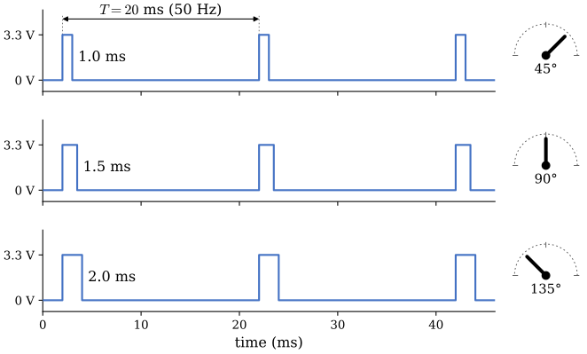
The DS3218 maps 500 to 2500 µs onto 180°, so the angle changes by
\[ \frac{180°}{2500\ \mu\text{s} - 500\ \mu\text{s}} = 0.09\ °/\mu\text{s}, \]
i.e. 11.1 µs per degree. Center is 1500 µs. Older servos use 1000 to 2000 µs for their full travel, which is why many libraries and radio systems default to that window. The 50 Hz frame dates from analog radio systems, which sent the pulses for all channels one after the other within each 20 ms frame. Digital servos such as the DS3218 accept faster frame rates as well, but 50 Hz works with every servo, and the steering does not need more.
Inside the servo
The housing holds a small brushed DC motor, a gearbox that reduces its speed many times over and multiplies its torque by the same factor, a potentiometer turned by the output shaft, and a control board. The potentiometer gives a voltage proportional to the shaft angle. The control board measures the width of each incoming pulse, converts it to the angle it stands for, and compares that with the potentiometer. The difference is the error, and the board drives the motor in the direction that makes the error smaller, harder the larger the error is. This is a proportional feedback controller packed into the servo.
Two consequences follow. First, the servo holds its position: when the steering pushes back on the horn, the shaft moves a little, an error appears and the motor pushes back. Second, the servo cannot be satisfied if the commanded angle lies beyond a mechanical stop. The error then never vanishes and the motor pushes at full current indefinitely. That is the binding the calibration avoids.
The controller ignores errors smaller than its deadband, about 3 µs for the DS3218. A 3 µs change in pulse width is \(3 \times 0.09° \approx 0.27°\) at the shaft. Without a deadband the motor would twitch back and forth around every target, chasing the noise in the potentiometer reading. With it, the servo stands still once it is within a quarter of a degree, and the pulse we send needs a resolution of about 1 µs or better to make use of all the precision the servo has.
The DS3218 data, as far as we could check them, are:
| Quantity | Value |
|---|---|
| Supply voltage (label) | 4.8 to 7.4 V on our servos (4.8 to 6.8 V on some versions) |
| Stall torque | about 19 kg·cm (1.9 N·m) at 5 V, 21.5 kg·cm (2.1 N·m) at 6.8 V |
| Speed (no load) | about 0.16 s per 60° at 5 V, 0.14 s at 6.8 V |
| Pulse range | 500 to 2500 µs over 180°, center 1500 µs |
| Deadband | 3 µs |
| Stall current | about 1.8 A at 5 V, 2.6 A at 6.8 V |
The voltage range is printed on the servo. The other values come from reseller listings and a servo database, which agree with each other on most points, and DSSERVO publishes no datasheet we could retrieve, so treat torque and current as approximate. A 270° version of the DS3218 exists as well; it uses the same pulse range spread over 270°.
Stall current and the supply
A motor at standstill has no back-EMF, so its current is limited only by the resistance of its winding. The servo draws this stall current every time it starts a large move, when it pushes against a load it cannot move, and while the linkage binds. For the DS3218 that is around 2.6 A at 6.8 V, compared with a few milliamperes while it stands still.
This is why the servo cannot run from a computer’s USB port, which delivers 0.5 to 0.9 A. The ESP32 itself needs some 100 to 250 mA with WiFi active, and its 3.3 V regulator needs about 4.5 V at VIN to keep working. When the servo pulls the 5 V of a USB port down, the 3.3 V supply of the chip sags with it, the chip’s brown-out detector resets it, and the serial monitor shows Brownout detector was triggered followed by the start-up text. The symptom is a board that restarts every time the servo moves. The XL4015 module, sold for up to 5 A, supplies the stall current with room to spare, and this is why servo and ESP32 share its rail.
The capacitor deals with what happens faster than the buck converter can follow. When the current steps from milliamperes to amperes, the inductance of the wires and the control loop of the converter delay the supply’s response by some microseconds, and the rail dips in the meantime. The capacitor feeds the servo during that time. The voltage drop of a capacitor \(C\) that alone supplies a current \(I\) for a time \(\Delta t\) is
\[ \Delta V = \frac{I\,\Delta t}{C}. \]
For \(I = 2.6\) A during \(\Delta t = 50\ \mu\text{s}\) from \(C = 470\ \mu\text{F}\) this is \(\Delta V = 2.6 \times 50 \times 10^{-6} / (470 \times 10^{-6}) = 0.28\) V, which the ESP32 does not notice. For a whole millisecond the drop would be 5.5 V, so the capacitor bridges short gaps only and the converter must carry the stall current itself. Close to the servo, the capacitor also keeps the current spikes out of the long wires to the converter, where they would disturb the ESP32 sharing those wires.
Generating the pulse with LEDC
The ESP32 has a PWM peripheral called LEDC (named for dimming LEDs) that produces pulse trains in hardware, so the program only sets the pulse width and the peripheral repeats the pulse every 20 ms by itself. LEDC has 16 channels. A channel counts from 0 up to \(2^b - 1\) once per period, where \(b\) is the resolution in bits, and keeps its output high while the count is below the duty value. ledcSetup(SERVO_CH, 50, 16) makes channel 0 count to 65 535 fifty times a second, and ledcAttachPin(SERVO_PIN, SERVO_CH) routes the channel to GPIO 13. Version 3 of the Arduino-ESP32 framework renamed these functions (ledcAttach(pin, freq, bits) and ledcWrite(pin, duty)); the code here uses the version 2 names that the pinned platform provides.
At 50 Hz and 16 bits one count lasts
\[ \frac{T}{2^{16}} = \frac{20\,000\ \mu\text{s}}{65\,536} = 0.305\ \mu\text{s}, \]
and a pulse of width \(t_p\) needs the duty
\[ \text{duty} = \frac{t_p \cdot 2^{16}}{T} = \frac{t_p \cdot 2^{16} \cdot f}{10^6}, \]
with \(t_p\) and \(T\) in microseconds and \(f\) in hertz. For center, \(1500 \times 65\,536 / 20\,000 = 4915.2\), which rounds to 4915, and the pulse produced is \(4915 \times 0.305 = 1499.9\ \mu\text{s}\). The ends of the DS3218’s range give 1638 at 500 µs and 8192 at 2500 µs. The module computes this in servoUsToDuty:
// Pulse width in microseconds to LEDC duty count, rounded to nearest:
// duty = us * 2^bits * freq / 1e6. The product reaches 8.2e9 for 2500 us at
// 50 Hz and 16 bits, beyond 32 bits, so it is formed in 64 bits.
inline uint32_t servoUsToDuty(uint32_t us) {
  uint64_t num = ((uint64_t)us << SERVO_RES_BITS) * SERVO_FREQ_HZ;
  return (uint32_t)((num + 500000ULL) / 1000000ULL);
}
The 64-bit arithmetic is needed because the product is formed before the division. For 2500 µs it is \(2500 \times 65\,536 \times 50 = 8.19 \times 10^9\), almost twice the largest 32-bit number, \(2^{32} - 1 = 4.29 \times 10^9\). In 32 bits the product would wrap around without any warning, and the servo would receive a wrong pulse. Dividing by the period first, \(t_p \cdot 2^{16} / 20\,000\), keeps the product at \(1.6 \times 10^8\) and would fit, but only as long as the frequency stays at 50 Hz; the 64-bit form works for any frame rate. Adding 500 000 before dividing by \(10^6\) rounds to the nearest count.
Sixteen bits is a deliberate choice. The servo resolves about 3 µs, and a count of 0.305 µs is ten times finer, so the step size of the PWM never limits the steering. With 10 bits a count would be \(20\,000/1024 = 19.5\ \mu\text{s}\), i.e. \(1.8°\) per step, coarse enough to see on the wheels. More than 16 bits brings nothing the servo can use, and 16 bits is well within what LEDC can do at 50 Hz.
The 16 channels share eight timers, and with the version 2 framework channels 0 and 1 use the same timer, as do 2 and 3, 4 and 5, and so on. Two channels on one timer have the same frequency and resolution. The servo therefore takes channel 0 at 50 Hz, channel 1 stays free, and the motor driver later takes channels 4 and 5, which share a timer at 20 kHz. In servoBegin the duty is written before the pin is attached, so the very first pulse on GPIO 13 is already the center pulse.
The ESP32Servo library
Most ESP32 servo examples use the library madhephaestus/ESP32Servo, added in platformio.ini as
lib_deps =
    madhephaestus/ESP32Servo@^3.0.0
It provides the Servo class known from Arduino boards: Servo steering; declares a servo, steering.attach(SERVO_PIN, 500, 2500) sets it up with its pulse limits, and steering.writeMicroseconds(1500) or steering.write(90) positions it. Underneath, the library uses the same LEDC peripheral and computes the same duty. It differs from our module in two ways that matter for the car. It picks the LEDC channel and timer itself, from its own record of which channels it has handed out, and it knows nothing about channels the motor code sets up with ledcSetup. It can therefore end up on a timer the motor uses and change its frequency. And in version 3.2.1, which ^3.0.0 resolves to at the time of writing, it uses 10 bits by default, the 19.5 µs steps computed above, unless steering.setTimerWidth(16) is called before attach.
Both are manageable, but the car combines a servo with a motor driver on fixed channels. Writing the servo with LEDC ourselves keeps every channel and timer in platformio.ini where we can see them, and the module is short enough to read in full. The library is a good choice for a project with several servos and no other PWM.
Exercises
Exercise 1
Compute the LEDC duty for a pulse of 1250 µs at 50 Hz and 16 bits, and the pulse width the servo actually receives. Repeat for a frame rate of 200 Hz. What is the longest pulse that fits in a 200 Hz frame, and why does the 32-bit product overflow at 200 Hz already for a pulse of 330 µs?
Exercise 2
A student’s steering calibration gives SERVO_LEFT_US=1960, SERVO_CENTER_US=1480 and SERVO_RIGHT_US=1100. Which pulse width does setSteering(0.5) send, and which does setSteering(-0.25) send? By how many degrees does the horn turn between full left and full right?
Exercise 3
The ESP32Servo library at its default 10 bits divides the 20 ms frame into 1024 counts. How many distinct pulse widths lie between 1220 and 1840 µs, and how many with 16 bits? Express the step size in degrees at the horn and compare it with the deadband.
Exercise 4
Open the Falstad circuit simulator and build a 7.0 V source with a 0.1 Ω series resistor (the wires and the converter’s output resistance) feeding a node with a 470 µF capacitor to ground. Add a 2.7 Ω resistor (a stalled servo at 7 V) through a switch from the node to ground, and a 1 kΩ load for the ESP32. Close the switch and read the node voltage on the scope. How far does it fall, and how much faster does it fall without the capacitor? What does the capacitor change, and what does it not change, once the switch has been closed for a few milliseconds?