10.5 Batteries, USB and the voltmeter
With a resistor in series the LED no longer needs the current limit of the lab supply, so we can run it from sources without one: a 9 V battery and a USB charger. This chapter does that, following Ben Eater’s third video, and uses the occasion to learn the most used measurement at the bench, the voltage between two points. With it we check that the voltages of the circuit add up, and we find a broken connection without looking for it.
Measuring a voltage
Set the dial of the multimeter to V⎓ (DC volts), put the black lead in COM and the red lead in VΩ. A voltage is always measured between two points, so both probes touch the circuit: the black probe on the lower point, usually the − of the source, and the red probe on the point we want to know. Nothing in the circuit is disconnected. If the display shows a minus sign, the probes are the wrong way round; the number is still correct. The multimeter has the details; this is all we need now.
The meter draws almost no current while it measures voltage (its input resistance is about 10 MΩ), so it shows the voltage that is there without changing it. Keep that in mind: it will matter in A signal is not a power supply.
Step 1: Measure the battery first
Before any new source is connected to a circuit, we measure it. Touch the black probe to the − terminal of the 9 V battery and the red probe to the +. A new alkaline battery reads a little above its 9 V nominal, typically 9.3 to 9.6 V, and a used one less. The battery’s datasheet1 lists its nominal voltage and the voltage at which it counts as empty, 4.8 V. A battery is a source whose voltage depends on how full it is, so the measured value is the one to calculate with.
Write the measured voltage in the log and predict the LED current with the 1 kΩ resistor from the last chapter:
\[ I = \frac{9.3 - 1.9}{1000}~\text{A} = 7.4~\text{mA} \]
for a battery measured at 9.3 V.
Step 2: Build
Connect the battery snap to the breadboard rails, red wire to the + rail and black wire to the − rail. Put the 1 kΩ resistor from the + rail to a free column, the LED from that column to another one with its long leg on the resistor side, and a jumper wire from the short leg’s column to the − rail.
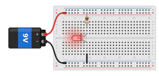
Snap the battery on last. The LED lights.
Step 3: Measure the voltage budget
Measure three voltages, as Ben does from 2:00 in the video: across the battery, across the LED and across the resistor (Figure 10.5.2). Each time the black probe goes on the end nearer to the − of the battery.
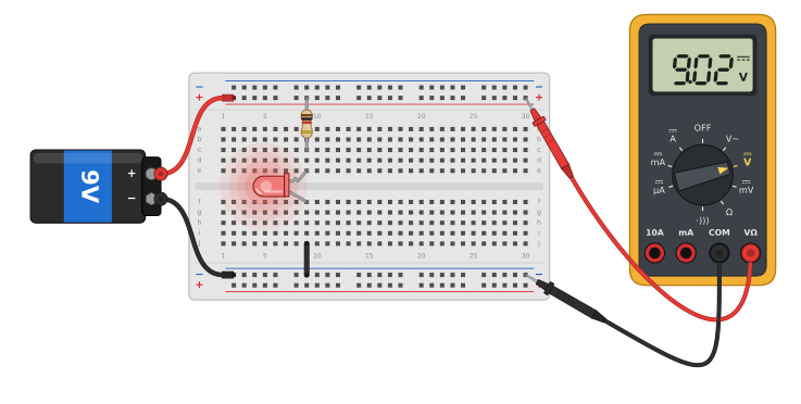
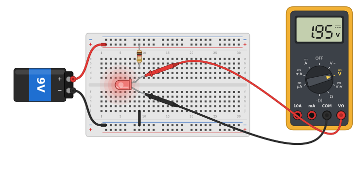
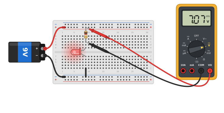
Ben reads 9 V across the battery, 1.95 V across the LED and 7.12 V across the resistor. The resistor and the LED together take what the battery gives, 7.12 V + 1.95 V ≈ 9.07 V, which is the voltage budget measured. Check the sum with your own numbers. A difference of a few hundredths of a volt comes from the meter’s last digit; anything larger means a measurement went wrong.
The resistor voltage also gives the current without breaking the circuit. With the measured resistance from the log, \(I = U_R/R\), e.g. \(7.12/1000~\text{A} = 7.1~\text{mA}\). Every resistor in a circuit is a current meter, if we know its value.
Figure 10.5.3 has the same circuit with three voltmeters. Drag the Battery voltage slider from a fresh 9.6 V down to a tired 6 V: the LED voltage hardly moves, the resistor takes up all of the change, and the sum always equals the battery voltage.
The voltmeter walk
The voltage budget is also the quickest way to find a fault, and we practise it now on purpose. Disconnect the battery and pull the short leg of the LED out of its column and into the neighbouring one, so that the loop is open. Reconnect the battery. The LED is dark.
Clip or hold the black probe on the − rail and leave it there. Then walk the red probe along the path of the current and write each reading down.
| Red probe on | Working circuit (V) | Broken circuit (V) |
|---|---|---|
| + rail | 9.3 | 9.3 |
| resistor leg towards the LED | 1.9 | 9.3 |
| LED short leg | 0 | several volts |
| − rail | 0 | 0 |
In the broken circuit both ends of the resistor read the full battery voltage. A resistor with the same voltage at both ends carries no current (Ohm’s law with \(U = 0\)), so no current flows anywhere in the loop: the loop is open somewhere. The voltage stays high past the LED and drops to zero only at the − rail, so the break lies between the last point that reads high and the first that reads zero, here between the short leg and the rail. Look there and the loose leg is found.
The same walk works on every circuit in this book, including the car: black probe on ground, red probe from the source along the path, and the fault lies where the readings stop agreeing with the prediction. Put the LED leg back and check that the checkpoint values return.
Step 4: Power from USB
A USB charger gives 5 V and is easier to keep around than batteries. Ben cuts an old USB cable and uses its red and black wires; a small USB breakout board with pins marked VBUS (or 5V) and GND does the same job without cutting anything. Like Ben, use a wall charger, never a USB port of a computer. A mistake on the breadboard, a short circuit or a wire from another source, can then at worst damage a cheap charger.
Measure first: black probe on GND, red on VBUS. The USB 2.0 specification allows 4.75 V to 5.25 V at the source,2 and newer chargers up to 5.5 V, so anything in that range is a healthy charger. Then connect the breakout to the rails and keep the circuit as it is: with 1 kΩ the LED carries about 3 mA, and with 220 Ω about 14 mA as in the last chapter.
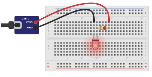
VBUS goes to the + rail and GND to the − rail.
Repeat the voltage budget with the USB supply. Ben reads 5 V across the supply and 1.91 V across the LED: with less supply voltage the LED voltage drops only a little, and the resistor takes the rest.
Exercises
Exercise 1: Loaded and unloaded
Measure the battery voltage with the LED circuit disconnected, then with it connected. How large is the difference? Repeat with the USB charger. Keep the numbers: the next chapters show a source where the difference is not small at all.
Exercise 2: A walk with a different fault
Ask a lab partner to introduce one fault into your circuit while you look away: a resistor leg moved by one column, the LED turned around, or a jumper wire moved off the rail. Find it with the voltmeter walk alone, without looking at the board, and write down the readings that gave it away.
Exercise 3: The tired battery
Use the slider in Figure 10.5.3 to find the battery voltage at which the LED current falls to 3 mA. At what voltage does the battery’s datasheet count it as empty, and is the LED still lit then?
Energizer, 522 product datasheet, form 522GL1019. The capacity chart counts the battery as empty at 4.8 V. data.energizer.com↩︎
USB Implementers Forum, Universal Serial Bus Specification, Revision 2.0, Table 7-7, DC Electrical Characteristics. A later amendment (the VBUS Max Limit ECN) raises the upper limit to 5.5 V, as for USB-C chargers. usb.org↩︎