10.2 Working at the bench
A circuit that is wired up in one go and switched on to see what happens usually does nothing, and then nobody knows why. There may be one fault or five, in the wiring, the parts, the supply or the code, and every one of them hides the others. Mechatronics done well looks different. We build the circuit in small steps, predict what each step should do, measure that it does it, and write the result down. When something fails, only the last small step can be to blame, and we can always go back to the previous state that worked.
This chapter describes that way of working and the equipment on the bench. The next chapters apply it to the simplest circuit there is, an LED with a resistor, following the first five videos of Ben Eater’s series Digital electronics. Ben does every experiment on camera with a lab supply, a breadboard and a multimeter, and each chapter shows his video next to the same experiment with our parts. Watch the video first, then do the experiment yourself.
The loop
Every step at the bench runs through the same five moves.
- Predict. Before switching on, write down what should happen: the LED lights, the current is about 14 mA, the voltage at this point is about 1.9 V. A prediction can be rough. Without one, we cannot tell a working circuit from a broken one.
- Change one thing. Add one part, move one wire, change one value in the code. Never two at a time.
- Measure. Use the multimeter, not the eye. An LED that “looks fine” may be carrying three times its rated current.
- Compare. Does the measurement agree with the prediction? A difference of a few percent is normal; parts have tolerances. A factor of two, or a sign the wrong way, means that the prediction or the circuit is wrong, and we find out which before going on.
- Record. Write the values in the lab log, and when a step is complete, mark it as a checkpoint.
The loop feels slow the first time. It is the fastest way we know, because the time spent hunting for faults drops to almost nothing.
Checkpoints and rolling back
A checkpoint is a state of the circuit that we have measured and know to work. Each chapter in this part marks its checkpoints in a box like this one:
At a checkpoint we record what is needed to rebuild the same state: a photo of the breadboard taken from straight above, the measured values, and for code the commit in the project’s Git history (or at least a copy of the project folder). When a later step fails and we cannot see why within a few minutes, we go back. We undo the last change, or rebuild from the photo, and check that the checkpoint values come back. Then we take the failed step again, smaller this time.
Going back is not a defeat. Once the old values are back, we know the fault was in the last change, and that change is small.
When it does not work
Faults are found by measuring, not by staring at the wiring. Four techniques cover nearly everything in this book, and each later chapter uses them.
Roll back to the last checkpoint, as above.
Walk with the voltmeter. Clip the black probe to ground and leave it there. Touch the red probe to each point of the circuit in turn, from the supply towards ground, and compare each reading with the prediction. The fault sits between the last point that reads right and the first that reads wrong. Batteries, USB and the voltmeter shows this on the LED circuit.
Compare with a known-good copy. Build a second, identical circuit that works, or keep the one from the last checkpoint, and measure the same point in both. Ben Eater does exactly this in his fourth video, and we repeat it in A signal is not a power supply.
Swap one part. If the circuits differ, exchange one part (the LED, the resistor, a jumper wire) between the good and the bad circuit. If the fault moves with the part, the part is faulty. If it stays, the part is fine.
The lab log
The log is a notebook, paper or a file, with one entry per step. A table is enough:
| Step | Change | Predicted | Measured | OK? |
|---|---|---|---|---|
| 1 | LED on supply at 1.80 V | dim, a few mA | 2 mA, dim | yes |
| 2 | supply to 1.90 V | brighter, about 15 mA | 16 mA | yes |
| 3 | 220 Ω added, supply 5.00 V | 14 mA | 13.6 mA | yes, checkpoint |
The log costs a minute per step. It pays off the first time a circuit that worked yesterday does not work today, because it tells us exactly what worked means.
The breadboard
A breadboard holds parts and wires without soldering. Under each row of five holes lies a metal spring clip, so the five holes are connected to each other and to nothing else. Two parts are connected when one leg of each sits in the same group of five. Along the edges run the power rails, long strips marked + (red) and − (blue) where the supply and ground are distributed. On many half-size boards each rail is one strip along the whole board. On some full-size boards the rail is split in the middle, which can be checked with the continuity beeper of the meter (Continuity and diode test).
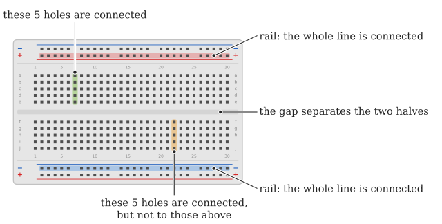
Three mistakes account for most breadboard faults. A part whose two legs sit in the same group of five is short-circuited and does nothing. A leg that went into the hole next to the intended one is connected to the wrong node. A leg that is too short, or a stranded wire that is not twisted, sits loose and makes contact only sometimes. Push every leg in until it stops, and look at the board from straight above before switching on.
The bench power supply
Every new circuit in this book is powered first from an adjustable bench power supply with a current limit, never straight from a battery. Two properties make it the most useful instrument on the bench. We can set any voltage we like, so the same supply stands in for a 9 V battery, a 5 V USB charger, a full 12.6 V car battery or a nearly empty one at 9.6 V, and we can test what the circuit does at each of them without waiting for a battery to run down. And we can set the highest current the supply will deliver, so a wiring mistake shows up as a lamp on the front panel and not as smoke. If you buy a supply for your own bench, buy one with both knobs; a fixed-voltage adapter or a supply without a current limit gives up exactly these two advantages.
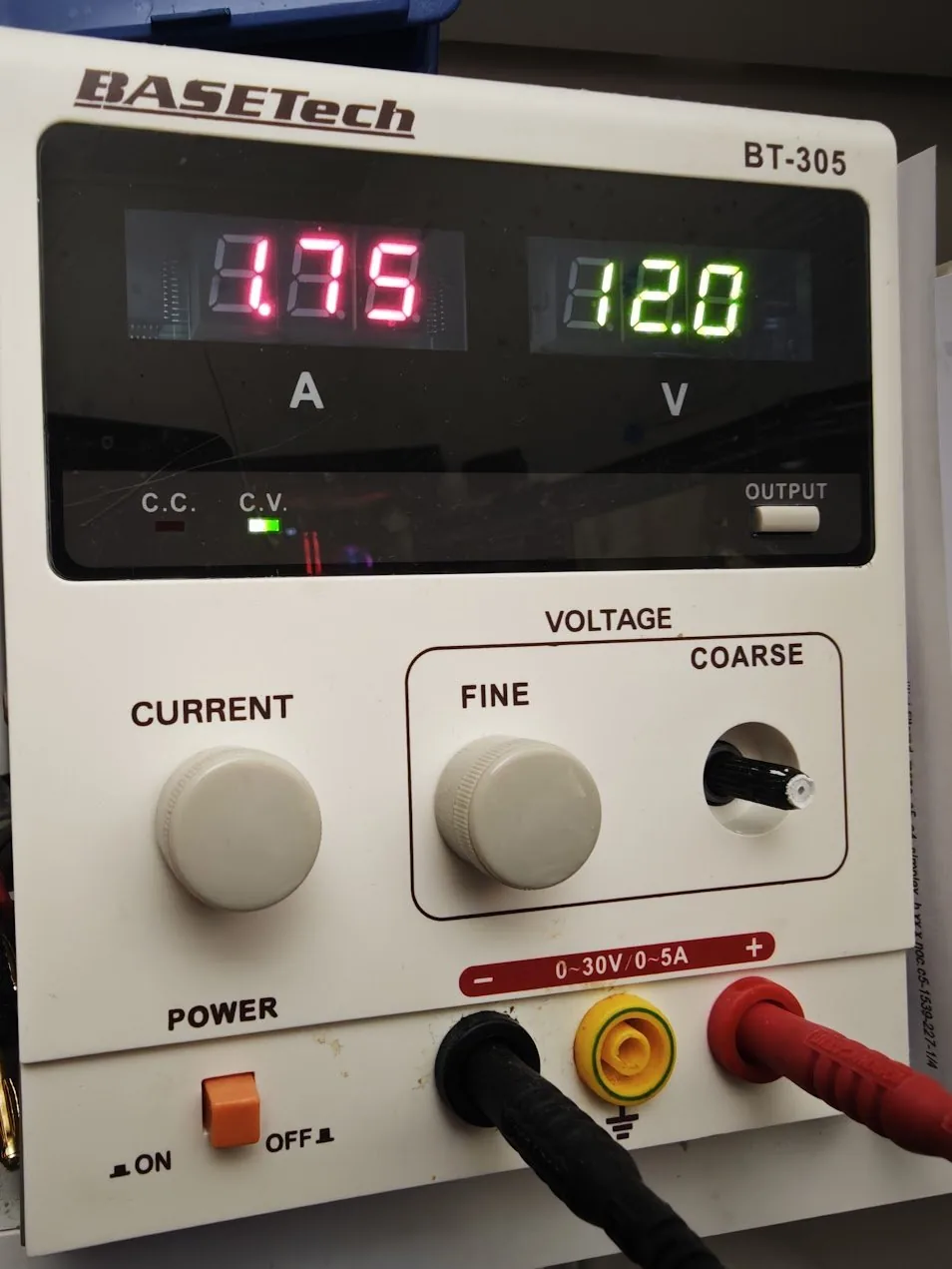
The VOLTAGE knobs (COARSE for large steps, FINE for the last tenths) set the voltage the supply tries to hold at its output. The CURRENT knob sets the current limit, the highest current the supply will deliver. The yellow terminal is connected to the mains earth; we leave it unused and take our ground from the black − terminal.
As long as the circuit draws less current than the limit, the supply holds the set voltage and the C.V. (constant voltage) lamp is lit, as in Figure 10.2.2. When the circuit tries to draw more, the supply lowers its voltage until the current equals the limit, and the C.C. (constant current) lamp lights instead. The C.C. lamp is a warning: the circuit wants more current than we allowed. Either the limit is too low for this circuit, or the circuit has a fault such as a short circuit.
Set the supply up the same way every time.
- Press OUTPUT so that the output is off, and disconnect the circuit. Turn the CURRENT knob to minimum.
- Switch on with POWER and set the voltage with COARSE and FINE while reading the green display. Set it to zero if we will raise it slowly.
- Set the current limit. Connect the red and black leads to each other with a short wire, switch the output on, and turn CURRENT until the red display shows the limit we want; the C.C. lamp is lit, since the short asks for more. A short circuit is harmless to a supply in C.C. mode. Switch the output off and remove the wire. (Some supplies instead show the limit while a button marked LIMIT or I-SET is held.)
- Connect the circuit, red lead to +, black lead to −, and switch the output on.
- Look at the lamps and the displays. C.V. and the expected current: carry on. C.C.: switch the output off and find out why.
The displays have limited resolution. The BT-305 shows the current in steps of 0.01 A, so the 14 mA of an LED circuit appears as 0.01 and anything below 10 mA as 0.00. Ben meets the same limit in his second video (“this isn’t the greatest ammeter”). The display is good enough to see whether a circuit draws about the right current and to catch a short circuit; when we need the milliamperes, we measure them with the multimeter, either in series (Measuring DC current) or as the voltage across a known resistor (the voltage budget).
A sensible current limit is a little above the current we predicted, e.g. 30 mA for an LED circuit that should draw 15 mA. If anything is wrong, the supply stops the current before a part is damaged. Batteries and USB chargers have no such knob, which is why a circuit moves to them only after it works on the bench supply.
The datasheet
Every part we use has a datasheet, a document from its manufacturer that states what the part does and what it tolerates. Search for the part number (printed on the part, the bag or the shop page) followed by the word datasheet, and prefer the PDF from the manufacturer’s own website. Reading datasheets is part of the work, and each chapter points to the one we need.
A datasheet is long, but three tables do most of the work. Absolute maximum ratings lists the values that must never be exceeded, not even for a moment: the highest current through an LED, the highest voltage on an ESP32 pin. Exceeding them may destroy the part at once, or slowly. Electrical characteristics lists what the part does in normal operation, under stated test conditions. Its columns Min, Typ and Max tell us the spread between individual parts: a red LED may be specified at 2.0 V typical and 2.5 V maximum at 20 mA, and the part on our bench can be anywhere in that range. Recommended operating conditions, when present, gives the range where the characteristics hold.
We design with the typical values, check that the circuit still works with the minimum and maximum ones, and stay well away from the absolute maximum ratings. Then we measure what our own part actually does.
Before switching on
Read this list before every new circuit is powered for the first time. After a few weeks it becomes a habit and takes ten seconds.
- The supply is set (voltage and current limit) before it is connected.
- Every LED has a resistor in series, and its long leg points towards +.
- No part has both legs in the same group of five holes.
- Red goes to +, black to −, and every ground is connected to every other ground.
- The meter’s red lead is in the
VΩjack, unless we are about to measure current. - We know what the circuit should do, and we have written the prediction down.
Further reading
Ben Eater’s playlist Digital electronics is the video companion of the next chapters. His later series on building an 8-bit computer on breadboards shows the step-by-step method at a scale of hundreds of wires.