10.6 The multimeter
Every circuit in this book is checked with a multimeter before it is trusted. The meter tells us whether the battery is charged, whether the buck converter really gives 7.0 V before the ESP32 is connected to it, how much current the LED draws and whether a wire that looks fine is broken inside. This chapter shows how to make those measurements without damaging the meter or the circuit. The guide comes first. How the meter works, and what its readings mean, follows after the guide.
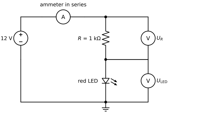
The first chapters of this part already used the meter for single measurements. This chapter collects everything it can do, as a reference to come back to. The circuit we measure throughout is the indicator LED of The series resistor: a red LED in series with a 1 kΩ resistor, fed from 12 V by the bench supply. Build it on the breadboard before starting.
The Guide
The jacks and the dial
A handheld multimeter has a dial and three or four jacks. The black lead always goes in the jack marked COM. The red lead goes in one of the others, depending on what we measure:
| Jack | Used for | Typical limit |
|---|---|---|
VΩ (often with a diode and a beeper symbol) |
voltage, resistance, continuity, diode test | 600 V or 1000 V |
mA or µA mA |
small currents | 200 to 600 mA, fused |
10A or A |
large currents | 10 A, often for at most 10 s at a time |
The limits printed next to the jacks of our own meter are the ones that count; the table gives typical values. On the dial, a straight line with a dashed line under it (⎓) means DC and a wave (~) means AC. Everything on the car is DC, so the settings we use are V⎓, mA⎓ and A⎓. Many meters choose the range by themselves (auto-range). Others have several positions per quantity, e.g. 2 V, 20 V and 200 V, and then we start at the highest range and step down.
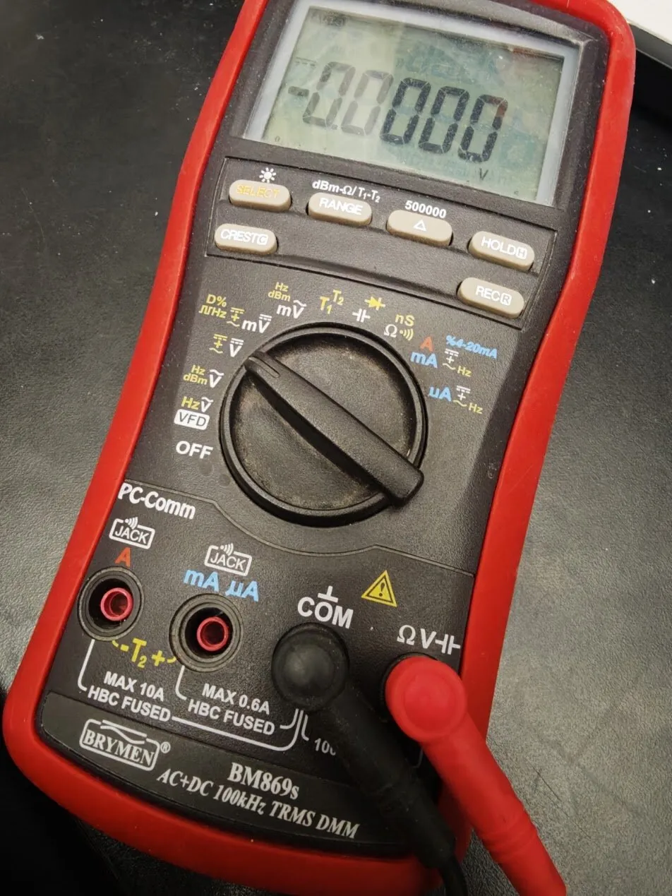
COM, the red one in ΩV. The two jacks on the left are A (max 10 A) and mA µA (max 0.6 A), each fused, with its limit printed below it.
Measuring DC voltage
Voltage is the difference in electrical potential between two points, so the meter needs to touch both. With the red lead in VΩ and the dial on V⎓:
- Touch the black probe to the lower point, usually ground (GND).
- Touch the red probe to the point we want to know.
- Read the display. A minus sign means the probes are the wrong way round; the reading is otherwise correct.
The meter is placed in parallel with what we measure, and nothing in the circuit has to be disconnected. With the black probe on ground and the red probe at the top of the resistor in Figure 10.6.1, we read the supply voltage, about 12 V. Moved to the point between resistor and LED, the red probe reads the voltage across the LED, about 2 V. The voltage across the resistor alone is found by putting the probes on its two ends, and it comes out near 10 V. The two parts add up to the supply voltage, which is Kirchhoff’s voltage law at work.
Whenever a new supply is part of the circuit, a battery, a buck converter or a lab supply, measure its voltage before connecting anything to it. This one habit protects the ESP32 more than anything else in the course. The gates for the power chain and the battery monitor ask for exactly this measurement.
Measuring DC current
Current is the flow of charge through a wire, so the meter has to become part of the wire. The circuit is opened at one point and the meter closes the gap, as the ammeter in Figure 10.6.1 does. This is called connecting the meter in series.
- Switch off the supply.
- Move the red lead to the
mAjack. Use the10Ajack instead if the current may exceed the limit of themAjack (a motor, a servo, anything powered directly by the battery). - Set the dial to
mA⎓(orA⎓for the10Ajack). - Open the circuit at one point, e.g. by lifting one end of the resistor out of the breadboard, and connect the probes to the two loose ends: red towards the supply +, black towards the rest of the circuit.
- Switch on and read the display. For the LED circuit, about 10 mA.
- Switch off, remove the meter, close the circuit again, and move the red lead back to
VΩ.
Step 6 is the one that is forgotten. With the red lead still in the mA jack, the meter is close to a short circuit between its probes, and the next voltage measurement then shorts whatever the probes touch.
An ammeter has a very small internal resistance, typically between 0.01 Ω and a few ohms, so that it does not disturb the current it measures. Placed across a 12 V supply, in parallel instead of in series, it is a short circuit. From a lab supply with its current limit set high or from the car’s LiPo battery, the current is then many amperes, and the fuse in the meter blows (or, in a meter without a fuse in the 10A input, the meter and the leads get hot). The fuse is there to protect us, and it is replaced with one of the same type and rating, never with a piece of wire.
An ammeter is always in series with something that limits the current: a resistor, an LED with its resistor, a motor.
If the display shows zero in the current mode in a circuit that clearly works, the fuse of that jack has probably blown. The meter can check its own fuse. With the leads in COM and VΩ and the dial on Ω, push the tip of the red probe into the mA jack. The meter then measures through the fuse and the shunt to COM: a few ohms means the fuse is intact, OL means it has blown.
Measuring resistance
With the red lead in VΩ and the dial on Ω, the meter sends a small known current through whatever is between the probes and shows the ratio of the resulting voltage to that current. Two rules follow from how the meter does this.
The circuit must be without power. A voltage from the circuit adds to the meter’s own small test voltage, and the reading becomes meaningless; in the worst case the meter is damaged.
The part must be out of the circuit, or at least one of its legs must be. Otherwise the meter’s test current also flows through every other path between the two probes, and the meter shows the resistance of the combination. A 10 kΩ resistor with another 10 kΩ path in parallel reads 5 kΩ.
Measure a resistor from the kit before using it. A 1 kΩ resistor with 5 % tolerance reads between 950 Ω and 1050 Ω. Hold the resistor by one leg, or lay it on the bench: fingers on both probes put the resistance of our body in parallel, which spoils readings above some tens of kilohms.
Continuity and diode test
The continuity mode (the beeper symbol, often on the same dial position as Ω) beeps when the resistance between the probes is low, below a threshold of some tens of ohms that depends on the meter. It answers yes-or-no questions with the power off: is this jumper wire broken, are these two breadboard rows connected, is the ground of the servo really connected to the ground of the ESP32?
The diode test (the diode symbol) sends a small current, typically around 1 mA, through the part and displays the voltage across it. A silicon diode reads about 0.5 to 0.7 V in the forward direction and OL (over limit) in reverse. A red LED reads about 1.6 to 1.8 V and often glows faintly. This is a quick way to find which leg is the anode: the LED lights when the red probe is on the anode. Blue and white LEDs have a higher forward voltage than many meters can supply in this mode and may read OL both ways even though they are fine.
The clamp meter for motor current
The motor of the car draws several amperes, more at start-up and under load. Opening the motor wire to insert a multimeter is impractical in the assembled car, and the stall current can exceed the 10 A of the 10A jack. A clamp meter measures the current without touching the circuit: its jaws close around one wire and sense the magnetic field that the current produces.
- Set the clamp meter to
A⎓(DC). An AC-only clamp meter cannot measure DC; check that the dial has a DC current position. - With the jaws closed and empty, press the zero button (
ZERO,RELorDC A ZERO). The magnetic sensor of a DC clamp has an offset that drifts and must be zeroed before every measurement. - Open the jaws around one conductor, e.g. the red motor wire. Around both motor wires the two currents flow in opposite directions, their fields cancel, and the meter reads zero.
- Read the current. The arrow on the jaw shows which direction counts as positive.
A clamp meter typically resolves 10 mA or worse, so it is the right tool for the motor and the battery current, and the wrong one for the 10 mA of an LED.
How the Meter Works
The guide tells us where to put the probes. This section explains why the meter has to be connected that way, and how much we can trust the number on the display.
Voltmeter and ammeter
Inside, a digital multimeter measures one thing only: a small DC voltage, which it converts to a number. Everything else is arranged around that measurement, as in Figure 10.6.3.
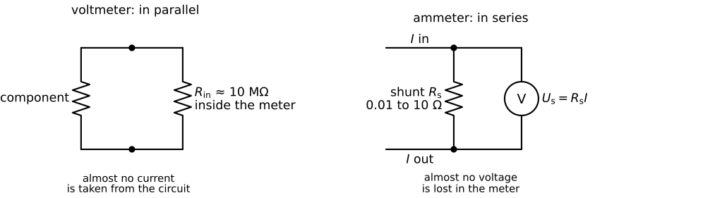
As a voltmeter, the meter presents a large input resistance \(R_{\mathrm{in}}\) between its probes, typically 10 MΩ for a handheld digital meter. The current it draws from the circuit is \(U/R_{\mathrm{in}}\), at 12 V only 1.2 µA, so the circuit behaves as if the meter were not there. An ideal voltmeter would have infinite input resistance. The difference matters only when the circuit itself has a high resistance. The battery divider of the car has 33 kΩ above and 10 kΩ below the midpoint, which seen from the midpoint is a source resistance of \(33 \cdot 10/(33 + 10)~\text{kΩ} = 7.7~\text{kΩ}\). Against 10 MΩ, the meter lowers the midpoint voltage by about \(7.7/10\,000 = 0.08~\%\), well below the accuracy of the meter.
As an ammeter, the meter passes the current through a small, precise shunt resistor \(R_{\mathrm{s}}\) and measures the voltage drop \(U_{\mathrm{s}} = R_{\mathrm{s}}I\). The meter knows \(R_{\mathrm{s}}\) and displays \(U_{\mathrm{s}}/R_{\mathrm{s}}\). An ideal ammeter would have zero resistance, so that inserting it changes nothing. A real one adds \(R_{\mathrm{s}}\) plus the resistance of the fuse and the leads to the circuit, and the voltage lost across the meter is called the burden voltage. Suppose the mA range of a meter has 1 Ω in total. In the 12 V LED circuit at 10 mA the burden voltage is \(1 \cdot 0.010~\text{V} = 10~\text{mV}\), nothing compared with the 10 V across the 1 kΩ resistor. A range meant for microamperes uses a much larger shunt, often hundreds of ohms, and inserted into the same circuit it would reduce the very current it is trying to measure. This is why the range is chosen to match the current.
The small \(R_{\mathrm{s}}\) also explains the warning in the guide. Across a 12 V supply, the ammeter with \(R_{\mathrm{s}} = 1~\Omega\) would ask for \(12/1~\text{A} = 12~\text{A}\), and the fuse is the only thing that stops it.
The same principle lets us measure current with the voltmeter alone. The resistor in the LED circuit is a shunt of its own. With \(R\) measured out of the circuit (say 994 Ω) and the voltage across it measured in the circuit (say 10.05 V), the current is \(I = U_R/R = 10.05/994~\text{A} = 10.1~\text{mA}\), without opening the circuit.
Resolution, accuracy and range
A digital meter shows a fixed number of counts. A 6000-count meter shows at most 5999 on its display, and the range decides where the decimal point is: on the 6 V range it shows up to 5.999 V, on the 60 V range up to 59.99 V. The last digit is the resolution of the reading. Auto-range picks the range with the best resolution that still holds the value, and a reading of OL means that the value exceeds the range.
Resolution is not accuracy. The manual gives the accuracy of each range in the form \(\pm(a~\% \text{ of reading} + b \text{ digits})\). Suppose the DC voltage range is specified as \(\pm(0.5~\% + 3)\) and the meter shows 12.08 V on the 60 V range. The uncertainty is \(0.005 \cdot 12.08~\text{V} + 3 \cdot 0.01~\text{V} = 0.06~\text{V} + 0.03~\text{V} = 0.09~\text{V}\), and the true voltage lies between 11.99 V and 12.17 V. The current ranges are usually less accurate than the voltage ranges, often around 1 %. For our circuits, where component values have tolerances of 5 %, this is more than good enough, but it means that a difference in the last digit between two meters is no reason for concern.
When the meter is too slow: the oscilloscope
A multimeter shows one number a few times per second, the average of whatever it sees. A PWM signal that switches between 0 and 3.3 V a thousand times per second reads as a steady voltage proportional to the duty cycle, and the shape of the signal stays hidden. The oscilloscope draws the voltage against time instead, with the voltage on the vertical axis and time on the horizontal, so we can see the pulses themselves.
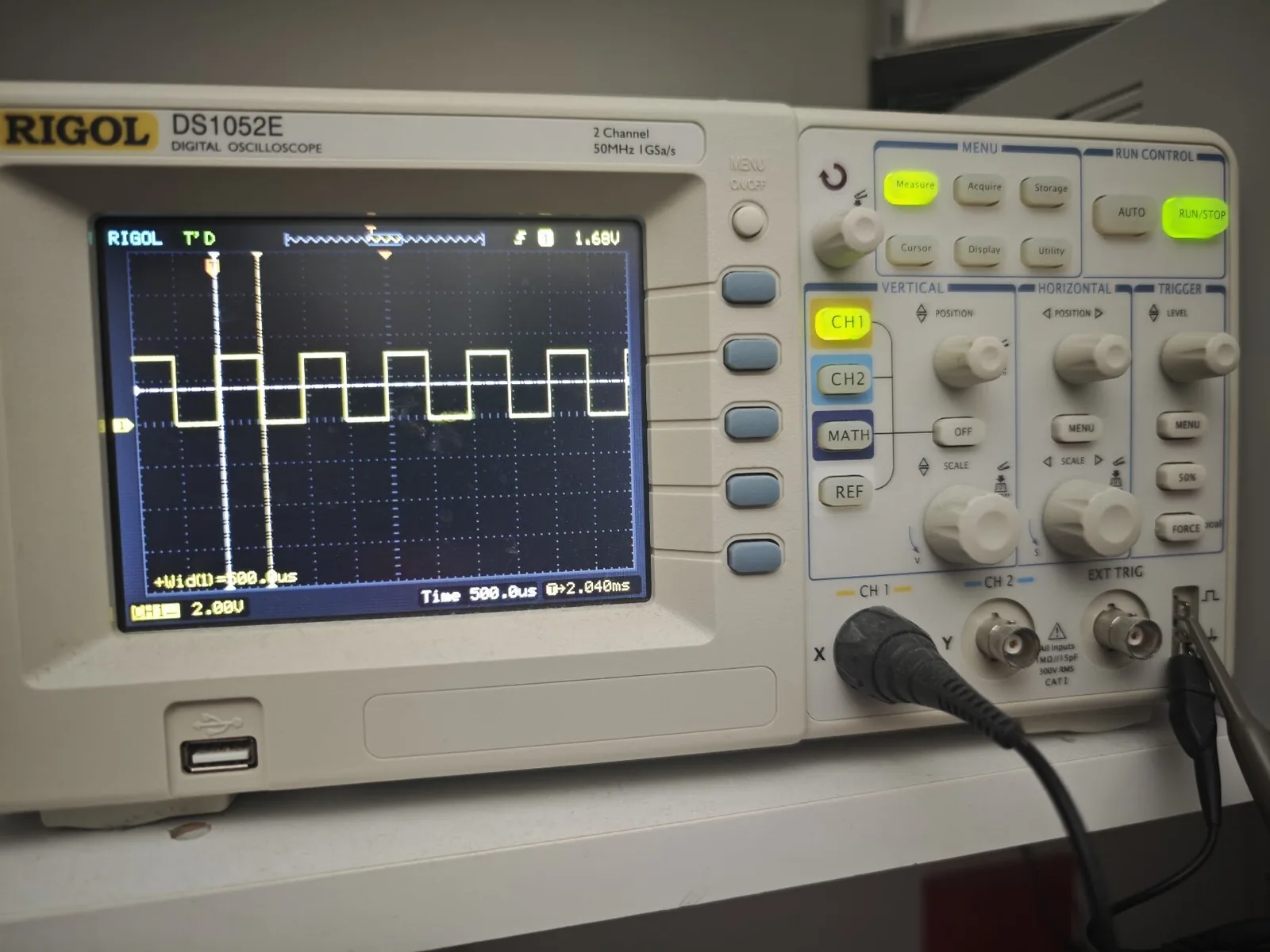
Figure 10.6.4 shows a 1 kHz square wave from the ESP32 on the Rigol DS1052E of the lab. The settings are printed on the screen: 2.00 V per vertical division and 500 µs per horizontal division. Each pulse is high for one division and the pattern repeats every two, so the period is 1 ms, the frequency 1 kHz and the duty cycle 50 %. The pulse is about one and a half divisions high, close to the 3.3 V logic level of the ESP32. The measurement at the bottom left, +Wid = 500.0us, is the scope’s own reading of the pulse width.
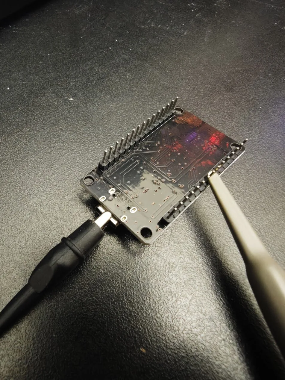
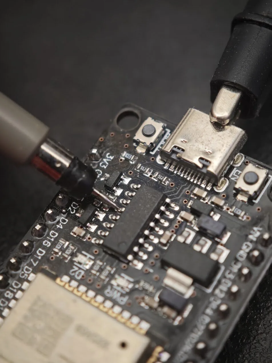
The scope connects to the circuit through a probe. Its ground lead clips to the circuit’s GND, and its tip goes on the point we want to see. Under the tip is a sprung sleeve: pulled back, it exposes a small hook that holds on a pin or a wire, so the hands stay free (Figure 10.6.5).
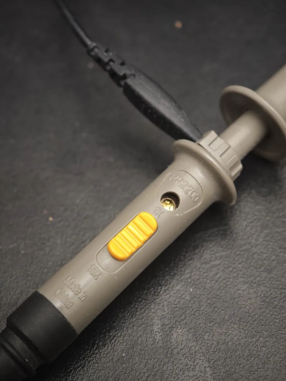
Most probes, like the Rigol RP2200 of Figure 10.6.6, have a switch marked 1X and 10X. At 1X the tip connects straight to the scope input, which is 1 MΩ in parallel with about 15 pF, printed next to the input sockets. At 10X a 9 MΩ resistor in the probe forms a voltage divider with the 1 MΩ of the scope, as in Voltage dividers: the scope sees one tenth of the voltage, and the circuit sees 10 MΩ instead of 1 MΩ. The probe’s capacitance is divided in the same way, and that is what matters for fast signals. The RP2200 is specified for 7 MHz at 1X and 150 MHz at 10X,1 so 10X is the setting for anything but the smallest signals. The scope must be told which setting the probe has, in the channel menu (Probe 1X or 10X). If the probe is at 10X and the scope thinks 1X, every voltage on the screen is ten times too small.
Typical mistakes
The list below collects the mistakes that destroy fuses, meters and boards in the lab. Read it once now and once again when a reading makes no sense.
- Red lead left in the
mAor10Ajack, then used to measure a voltage: a short circuit through the meter. Move the lead back after every current measurement. - Ammeter across a supply instead of in series: a short circuit, the fuse blows.
- Resistance measured in a powered circuit, or with the part still connected to other parts: the reading is wrong, and the meter may be damaged.
- Dial on AC (~) for a DC circuit: the meter shows nearly zero, or a meaningless number.
- Probe slipping between two pins: on the ESP32 board, a probe that touches
VINand a neighbouring pin at the same time can connect 7 V to a 3.3 V pin. Clip one lead to ground and hold the other probe with care, or measure on a breadboard row instead of on the board pins. - Clamp around both wires of a cable, or not zeroed: a reading of zero, or a constant offset.
- Low meter battery: many meters show a battery symbol, and readings drift before the meter switches off.
Exercises
Exercise 1: Voltages in the LED circuit
Build the LED circuit of Figure 10.6.1 from 12 V with a 1 kΩ resistor. Measure the supply voltage, the voltage across the resistor and the voltage across the LED. Check that the two part voltages add up to the supply voltage, and state by how much they differ. Compare the difference with the accuracy of the meter.
Exercise 2: Current three ways
In the same circuit, determine the current three ways: calculated from the nominal values with the resistor formula, measured with the meter in series on the mA range, and calculated from the measured resistor voltage and the measured resistance of the resistor (taken out of the circuit). Collect the three values in a table and explain the differences.
Exercise 3: Diode test
Use the diode test on a red LED and on a 1N4007 or similar silicon diode in both directions. Record the readings and identify the anode of each. Then place the LED in the 12 V circuit and compare its voltage at 10 mA with the diode-test reading. Explain why they differ, using the current-voltage curve of the LED in First light.
Exercise 4: The ESP32 pin under load
Run the blink program with an LED and a 150 Ω resistor on GPIO 2, as described in the PlatformIO chapter, with the LED on GPIO 23 as in A signal is not a power supply, and lengthen BLINK_MS to 5000 so that there is time to measure. Measure the voltage on the pin, relative to GND, when it is HIGH and when it is LOW, first with the LED connected and then with it removed. Use the difference to estimate the internal resistance of the pin driver, and use the result to recalculate the LED current.
Further reading
Ben Eater’s video series Basic digital electronics measures exactly these circuits with a multimeter on a breadboard; the first three parts, Experimenting with LEDs, Limiting current through an LED and Powering our LED circuit, go with this chapter.