A gear, a pulley or a coupling sits on a shaft, and the joint between the two has to carry the torque from one to the other. The part around the shaft is the hub, and the joint is a shaft–hub joint. There are two ways to make it. A joint locked by shape puts a part between shaft and hub that the torque cannot get past without shearing or crushing it: a key, a spline, a pin. A joint locked by friction presses the hub onto the shaft so hard that friction carries the torque: a clamped hub, a press fit, a shrink fit.
This chapter takes the shape-locked joints first, with the parallel key as the common case, then the clamped hub. Most of the chapter is about the interference fit, where the bore of the hub is made smaller than the shaft. That needs the ISO system of tolerances, which says how much smaller, and the stresses in a thick-walled cylinder, which turn the difference in diameter into a contact pressure.
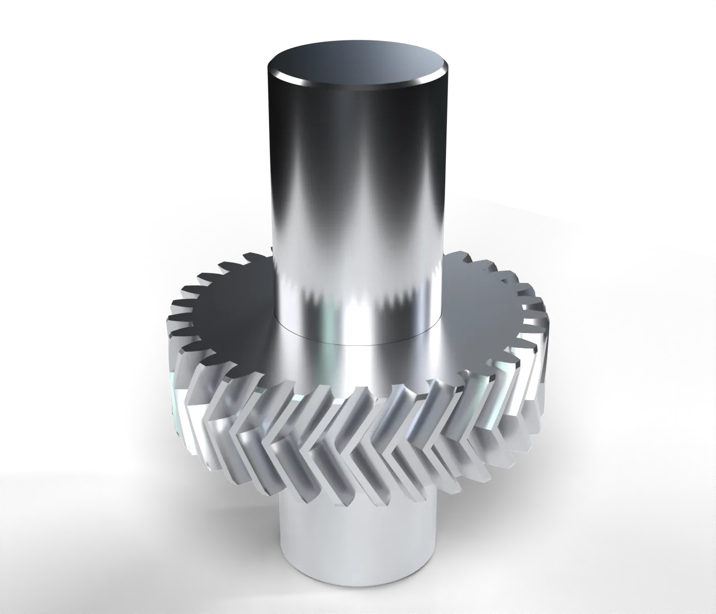
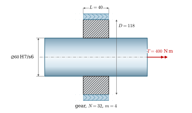
Figure 9.10.1: A herringbone gear shrink-fitted onto a 60 mm shaft. No key, no spline: friction alone carries the torque.
Locked by shape or by friction
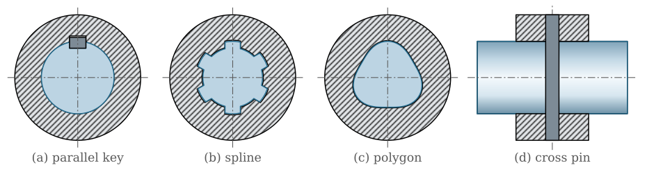
Figure 9.10.2 shows the four common shape-locked joints in section. The parallel key (a) sits half in a slot in the shaft and half in a slot in the hub, and the torque pushes it sideways. A spline (b) is many keys machined into the shaft itself, so the load is spread over several teeth and the hub can slide along the shaft, as in the gearbox of a car or the cassette of a bicycle. A polygon (c) is a shaft that is not round, a rounded triangle that the hub cannot turn on; the toolholders of machine tools use it because it centres the tool as it carries the torque. A cross pin (d) goes through hub and shaft and is sheared in two planes. It is cheap, and a pin made deliberately weak is a fuse: it shears when the drive jams, before anything more expensive breaks.
Figure 9.10.2: Joints locked by shape, in section: (a) a parallel key, (b) a spline, (c) a polygon, (d) a cross pin through hub and shaft.
A joint locked by friction has nothing between shaft and hub. The hub is pressed onto the shaft, by bolts in a clamped hub or by the hub’s own elasticity in an interference fit, and friction on the contact surface carries both torque and axial force. Nothing is cut into the shaft, so the shaft keeps its full strength, and the joint has no play, so a reversing torque does not hammer it loose. The price is precision: the grip depends on a difference in diameter of a few hundredths of a millimetre.
The parallel key
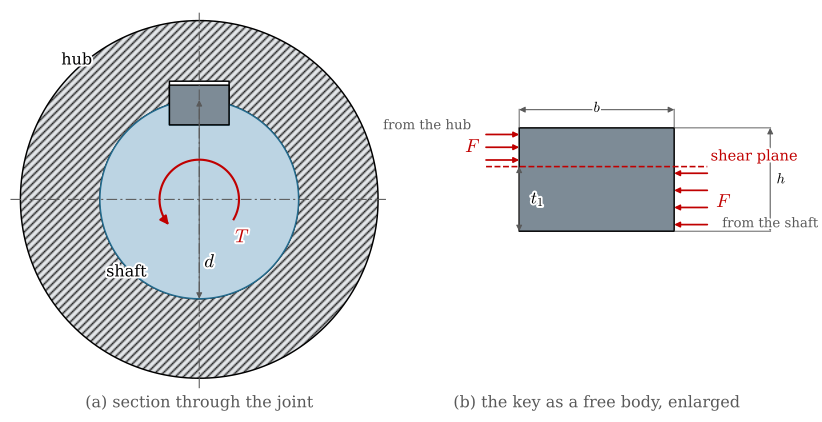
The key of Figure 9.10.3 is a steel bar of width \(b\) and height \(h\), sunk to the depth \(t_1\) in the shaft. Its sizes follow from the shaft diameter in a standard (DIN 6885 in Europe), so the designer chooses only its length \(l\). The torque \(T\) on the shaft reaches the key as a force on its side at the radius \(d/2\),
\[
F = \frac{2T}{d}
\tag{9.10.1}\]
and the hub pushes back with an equal force on the other side, higher up. The two forces are offset, so the key tries to tilt, but the slots hold it and we neglect the moment.
Figure 9.10.3: (a) A parallel key 12 × 8 on a 40 mm shaft. (b) The key as a free body: the shaft pushes on its right face over the depth \(t_1\), the hub on its left face over \(h - t_1\).
The key can fail in two ways. It can shear off in the plane of the shaft surface, over the area \(bl\),
\[
\tau = \frac{F}{b\,l}
\tag{9.10.2}\]
or one of its side faces can be crushed against the slot, which is a bearing stress on the part of the face that touches. The shaft touches the lower part, of height \(t_1\), and the hub the upper part, of height \(h - t_1\),
A standard key sits deeper in the shaft than in the hub, \(t_1 > h/2\), so the hub side has the smaller face and the larger stress. With the yield strength \(S_y\) of the weakest of key, shaft and hub, and a factor of safety \(n\), the length must satisfy \(\sigma_{b,h} \le S_y/n\) and \(\tau \le 0.577\,S_y/n\), the shear yield strength from the von Mises criterion. Shigley sizes the key the same way [1] but with the bearing face taken as \(h/2\), which is right for a square key in equally deep slots.
The keyway weakens the shaft. Its sharp corners concentrate the stress, and for a key in the usual end-milled slot Peterson’s charts give \(K_t \approx 2.1\) in bending and \(3.0\) in torsion [1]. For static torsion, Moore measured the strength of shafts with keyways a century ago and fitted the ratio of the strengths with and without the slot [2],
\[
e = 1 - 0.2\,\frac{b}{d} - 1.1\,\frac{t_1}{d}
\tag{9.10.4}\]
an empirical formula, valid for the proportions he tested. For standard keys it gives \(e \approx 0.8\): the keyway costs the shaft about a fifth of its torsional strength.
Example 1: A keyed gear
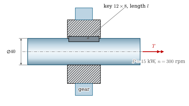
A gear on a 40 mm shaft transmits \(P = 15\) kW at \(n = 300\) rpm through a parallel key 12 × 8 with \(t_1 = 5\) mm (Figure 9.10.4). The key is of steel with \(S_y = 350\) MPa, weaker than shaft and hub. Find the key length for a factor of safety \(n_s = 2\), and how much the keyway weakens the shaft.
Figure 9.10.4: The gear of Example 1 on its shaft, in a section through the key.
The torque is \(T = P/\omega\), the force on the key follows from 9.10.1, and each failure mode gives a length from 9.10.2 or 9.10.3.
The bearing stress on the hub side decides: the key must be at least 46 mm long, more than twice what shear alone would ask for, so the hub must be about 50 mm long. Moore’s formula gives
\[ e = 1 - 0.2\,\frac{b}{d} - 1.1\,\frac{t_1}{d} =0.802 \]
so the shaft keeps 80 % of its torsional strength at the keyway. A shaft that is sized for torque alone must be made about 8 % thicker to make up for it, since the strength in torsion grows with \(d^3\) and \(0.8^{1/3} \approx 0.93\).
Pins and splines
A cross pin of diameter \(d_p\) through a shaft of diameter \(d\) (Figure 9.10.2 d) is cut in two planes, one on each side of the shaft. Each carries the force \(F\) at the radius \(d/2\), so \(T = 2F\,d/2 = F d\), and the shear stress in the pin is
The hole weakens the shaft more than a keyway does, so pins suit small torques, and the shear pin of a snow blower or a boat propeller is used precisely because it fails first. A spline is computed like a set of keys, with the bearing stress on the tooth flanks shared by the teeth; because the teeth are never cut perfectly alike, the standards count only about three quarters of them as carrying load. Retaining rings in grooves locate a hub axially but carry no torque; their grooves are sharp, with \(K_t\) around 5 in bending [1], so they belong where the bending moment is small.
The clamped hub
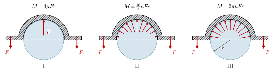
A clamped hub is split in two halves, or slit on one side, and bolts pull it tight around the shaft. It needs no precision: the bolts make the pressure, not the fit. How much torque the clamp carries depends on how the pressure spreads around the shaft, and that depends on how stiff the hub is. Figure 9.10.5 shows the three cases the lecture notes compare. In each the upper half is pulled down by a bolt force \(F\) at each ear, and the shaft pushes back on it.
Figure 9.10.5: The upper half of a clamped hub, pulled down by \(F\) at each ear, and three distributions of the pressure from the shaft: (I) a line load, (II) a pressure varying as \(\cos\varphi\), (III) a uniform pressure.
Let \(q(\varphi)\) be the pressure times the hub length, a force per radian, at the angle \(\varphi\) from the vertical. The vertical components of the pressure balance the two bolt forces, and every bit of pressure gives a friction force \(\mu q\,d\varphi\) at the radius \(r\). The lower half carries the same, so
\[
2F = \int_{-\pi/2}^{\pi/2} q(\varphi)\cos\varphi \; d\varphi, \qquad
M = 2\mu r \int_{-\pi/2}^{\pi/2} q(\varphi) \; d\varphi
\tag{9.10.6}\]
In case I hub and shaft are rigid and the bore slightly larger, so they touch along one line at the top: \(q\) is a single force \(2F\) and \(M = 4\mu F r\). In case II both are rigid but their surfaces give a little, so the pressure follows the approach of the surfaces, \(q = q_0\cos\varphi\). In case III the hub is so thin that it wraps the shaft like a band and the pressure is uniform, \(q = q_0\).
Code
phi, q0, F, mu, r = sp.symbols(r'varphi q_0 F mu r', positive=True)M_cases = {}for name, q in (('II', q0*sp.cos(phi)), ('III', q0)): q0_sol = sp.solve(sp.Eq(2*F, sp.integrate(q*sp.cos(phi), (phi, -sp.pi/2, sp.pi/2))), q0)[0] M_cases[name] = sp.simplify(2*mu*r*sp.integrate(q, (phi, -sp.pi/2, sp.pi/2)).subs(q0, q0_sol))
Solving the first of 9.10.6 for \(q_0\) and inserting it in the second gives
\[ \begin{aligned}\text{II:}\quad M &=\dfrac{16 F \mu r}{\pi}\approx 5.1\,\mu F r\\ \text{III:}\quad M &=2 \pi F \mu r\approx 6.3\,\mu F r\end{aligned} \]
The same bolts carry a torque between \(4\mu F r\) and \(2\pi\mu F r\), a range of more than 1.5, depending only on how the pressure spreads. A thick, rigid hub is the worst case, because it touches the shaft over the smallest arc. Since we rarely know which case applies, we design with case I,
\[
M = 4\mu F r
\tag{9.10.7}\]
and any spreading of the pressure is a reserve.
Example 2: A clamped lever
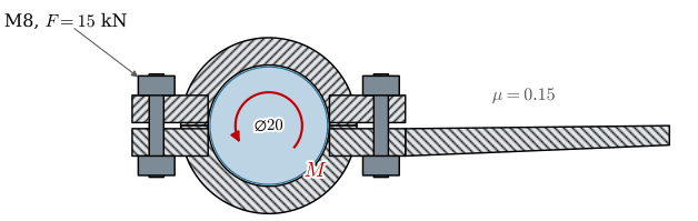
A lever is clamped onto a 20 mm shaft by two M8 bolts of class 8.8, each tightened to a preload of \(F = 15\) kN, which is about 65 % of its yield force (see the bolted joints chapter), as in Figure 9.10.6. The friction coefficient is \(\mu = 0.15\). What torque does the clamp carry?
Figure 9.10.6: The clamped lever of Example 2.
The recipe is 9.10.7 for the design value and the results of 9.10.6 for the two cases with a spread pressure.
Code
mu_2, F_2, r_2 =0.15, 15e3, 10.0# -, N, mmM_2 = {k: v.subs({mu: mu_2, F: F_2, r: r_2})/1e3for k, v in M_cases.items()}M_2['I'] =4*mu_2*F_2*r_2/1e3# N m
We would rate the clamp at 90 N·m. The preload itself scatters by about ±25 % when the bolts are tightened with a torque wrench, so the design value must also take the lowest preload, and an 8.8 bolt cannot be tightened much harder. A larger torque needs a longer hub with more bolts, or a different joint.
Tolerances and fits
No shaft is made exactly 60 mm in diameter. The drawing gives a basic size, and a range of sizes that is acceptable around it. The ISO system [3] gives each range a short code, a letter and a number, so that a hole and a shaft made in different workshops fit together the way the designer intended. Capital letters are for holes and small letters for shafts, and a fit is written with the hole first: 60 H7/s6 is a hole of basic size 60 mm in tolerance class H7 with a shaft in class s6.
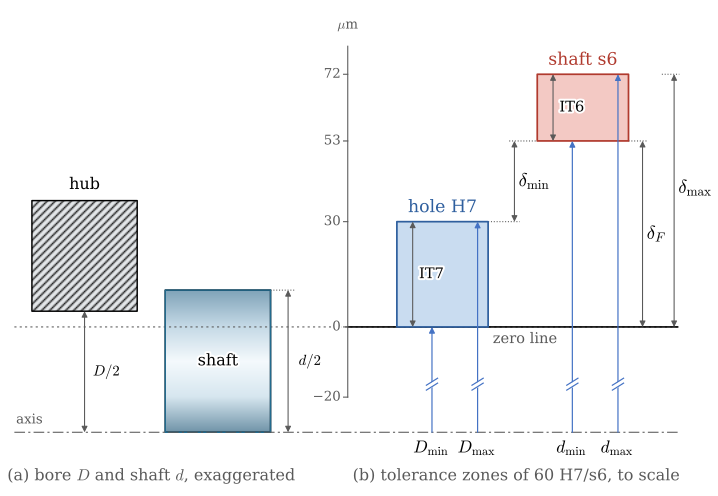
Figure 9.10.7: (a) In an s fit both the bore \(D\) and the shaft \(d\) lie above the basic size, the shaft further, so it is larger than the bore. (b) The tolerance zones of 60 H7/s6 drawn to scale above the zero line, which is the basic size. The tolerance grades IT7 and IT6 set the heights of the zones, the fundamental deviation \(\delta_F\) the position of the shaft’s zone, and the zones give the smallest and the largest interference.
The number is the tolerance grade. It sets the width of the zone, \(\Delta D\) for a hole and \(\Delta d\) for a shaft, and grows with the size, since a large part is harder to make to the same absolute accuracy: IT7 is 21 µm at 25 mm and 30 µm at 60 mm. The letter is the fundamental deviation\(\delta_F\), the distance from the basic size to the nearer edge of the zone. A hole in class H starts exactly at the basic size, and most fits are chosen on this hole basis, because a hole is made with a fixed tool, a reamer, and a shaft is easily turned or ground to any size. For the hole, then,
\[
D_\min = D, \qquad D_\max = D + \Delta D
\tag{9.10.8}\]
The shaft letters c to h lie below the basic size and give clearance; their deviation is the upper edge of the zone. The letters k to u lie above, their deviation is the lower edge, and they give transition or interference fits,
\[
d_\min = d + \delta_F, \qquad d_\max = d + \delta_F + \Delta d
\tag{9.10.9}\]
The interference is the shaft diameter minus the bore diameter, and a fit has a whole range of it, from the smallest shaft in the largest hole to the largest shaft in the smallest hole,
as Figure 9.10.7 shows. A negative interference is a clearance. A fit whose range spans zero is a transition fit: a given pair may slide together or need a press. The grip of an interference fit must be designed for \(\delta_\min\) and its stresses checked for \(\delta_\max\).
Reading these values from tables is mechanical work, so MechanicsKit does it. Its module mechanicskit.fits holds the tolerance grades and the fundamental deviations of [1] (Tables A-11 and A-12, which reproduce ISO 286-2 [4]) for sizes up to 400 mm, and two functions that apply 9.10.8 to 9.10.10. limits(fit, d) returns the deviations of hole and shaft in micrometres, \(((EI, ES), (ei, es))\), where \(EI = 0\) and \(ES = \Delta D\) for the hole and \(ei\), \(es\) are the lower and upper deviation of the shaft, so that \(d_\min = d + ei\). interference(fit, d) returns \((\delta_\min, \delta_\max)\) in micrometres, negative for a clearance. For the fit of Figure 9.10.7:
from mechanicskit.fits import limits, interferencelimits('H7/s6', 60), interference('H7/s6', 60)
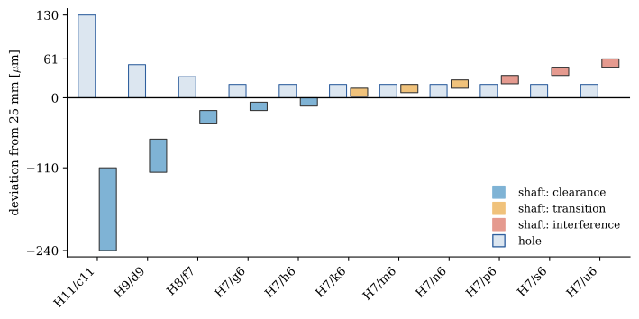
The ISO system offers far more combinations than anyone needs, so workshops keep to a short list of preferred fits. Table 9.10.1 lists them with the jobs they are used for, and the range of interference at 25 mm, computed with interference; a negative value is a clearance. The list itself is mechanicskit.fits.PREFERRED_FITS, which the ISO fits notebook uses as well. The same fits are drawn to scale in Figure 9.10.8.
Code
from mechanicskit.fits import PREFERRED_FITS, interferencerows = ['| Fit | Character | Typical use | Interference at Ø25 [µm] |','|:--|:--|:----------|--:|']for fit, character, use in PREFERRED_FITS: lo, hi = interference(fit, 25) sign =lambda v: f'{v:+d}'if v else'0'# noqa: E731 rows.append(f'| {fit} | {character} | {use} | {sign(lo)} to {sign(hi)} |')Markdown('\n'.join(rows))
Table 9.10.1: Preferred hole-basis fits [1, Table 7-9] with typical uses. The interference runs from its smallest to its largest value; negative values are clearances.
Fit
Character
Typical use
Interference at Ø25 [µm]
H11/c11
loose running
hinge pins of farm and construction machinery, clevis pins, linkages that tolerate play
-370 to -110
H9/d9
free running
idler and loose pulleys, plain bearings at high speed or with large temperature changes
-169 to -65
H8/f7
close running
shafts in plain bearings of gearboxes, pumps and machine tools
-74 to -20
H7/g6
sliding
sliding gears and clutch members, guide pins and spigots that must locate accurately
-41 to -7
H7/h6
locational clearance
gears and pulleys on keyed shafts that must come off, flange spigots, pins in removable covers
-34 to 0
H7/k6
locational transition
pulleys and couplings on keyed shafts, tapped on with a mallet
-19 to +15
H7/m6
transition
hardened dowel pins (ISO 8734) in reamed holes, located parts that are seldom taken apart
-13 to +21
H7/n6
locational transition
bushes and gears that must not move, pressed in, armatures on motor shafts
-6 to +28
H7/p6
locational interference
bushings and sleeves pressed into housings, valve seats
+1 to +35
H7/s6
medium drive
gears, couplings and flanges fixed for good by press or shrink fit; the tightest fit for cast iron
+14 to +48
H7/u6
force fit
shrink fits that carry large torques by friction alone: gear rims, built-up crankshafts
+27 to +61
Code
from mechanicskit.fits import PREFERRED_FITS, limits, kindd_fig =25fig, ax = plt.subplots(figsize=(7.5, 3.8))kind_color = {'clearance': '#7fb3d5', 'transition': '#f0c27b', 'interference': '#e59a8f'}for i, (fit, _, _) inenumerate(PREFERRED_FITS): (EI, ES), (ei, es) = limits(fit, d_fig) ax.add_patch(plt.Rectangle((i -0.38, EI), 0.34, ES - EI, fc='#dce6f0', ec='#2f5f9e', lw=0.8)) ax.add_patch(plt.Rectangle((i +0.04, ei), 0.34, es - ei, fc=kind_color[kind(fit, d_fig)], ec='0.2', lw=0.8))ax.axhline(0, color='k', lw=1)for k, c in kind_color.items(): ax.plot([], [], 's', color=c, ms=10, label=f'shaft: {k}')ax.plot([], [], 's', color='#dce6f0', mec='#2f5f9e', ms=10, label='hole')ax.set_xticks(range(len(PREFERRED_FITS)), [f for f, _, _ in PREFERRED_FITS], rotation=45, ha='right')ax.set_xlim(-0.6, len(PREFERRED_FITS) -0.4)ax.set_ylim(-250, 140)ax.set_yticks([-240, -110, 0, 61, 130])ax.set_ylabel(r'deviation from 25 mm [$\mu$m]')ax.legend(loc='lower right', frameon=False, fontsize=9)for s in ('top', 'right'): ax.spines[s].set_visible(False)plt.tight_layout()plt.show()
Figure 9.10.8: The tolerance zones of the preferred fits at a basic size of 25 mm: the hole (left of each pair) always starts at the zero line, and the letter of the shaft moves its zone from clearance through transition to interference.
A tolerance is only worth asking for if the workshop can make it. Table 9.10.2 relates the grades to the processes that reach them in normal production; a careful operator on a good machine does better, a worn machine worse. The last row is a printed part: a hole from a fused-filament printer is a grade or two coarser than a drilled one, and comes out undersize. The table is mechanicskit.fits.PROCESSES.
Code
from mechanicskit.fits import PROCESSES, tolerancerows = ['| Process | Makes | Typical grade | Tolerance at Ø25 [µm] |', '|:--|:--|:--:|--:|']makes = {'both': 'holes and shafts', 'hole': 'holes'}for name, feature, lo, hi in PROCESSES: rows.append(f'| {name} | {makes[feature]} | IT{lo}–IT{hi} | {tolerance(lo, 25)}–{tolerance(hi, 25)} |')Markdown('\n'.join(rows))
Table 9.10.2: Tolerance grades reached by common processes, as a rule of thumb from workshop practice.
Process
Makes
Typical grade
Tolerance at Ø25 [µm]
honing, lapping
holes and shafts
IT4–IT5
6–9
grinding
holes and shafts
IT5–IT7
9–21
reaming, fine boring
holes
IT6–IT8
13–33
turning, boring
holes and shafts
IT7–IT11
21–130
milling
holes and shafts
IT8–IT11
33–130
drilling
holes
IT10–IT13
84–330
fused-filament printing, as printed
holes and shafts
IT12–IT14
210–520
What a tolerance costs
“Design in CAD is not design until it is manufacturable.”
— Mirza Cenanovic
In CAD every dimension is exact, and a tolerance is a number typed into a box. In the workshop it is an instruction that has a price. A tighter grade needs a finer process, and usually one more operation: a shaft turned to IT9 must then be ground to reach IT6, and a drilled hole must be reamed to reach IT7. Each operation adds machine time, a set-up and tooling. The part must also be measured. A dimension of \(\pm 0.1\) mm is checked with a caliper; an IT6 shaft needs a micrometer or a snap gauge, and the measurement itself must be made at a known temperature. A 60 mm steel shaft grows by \(\alpha d = 0.7\) µm per degree, so a part still warm from the grinder, 10 °C above the room, measures 7 µm too large, more than a third of its IT6 tolerance of 19 µm. And when the natural scatter of a process is close to the tolerance, some parts fall outside it and are scrapped.
The grades grow geometrically, each about 1.6 times wider than the one before, so two grades tighter is a zone less than half as wide, and often a different machine. The cost does not grow evenly with it: it stays low while the process reaches the grade comfortably and climbs steeply as the tolerance approaches what the process can do at all.
Two consequences follow for the fits of this chapter. First, the letter of a fit costs nothing and the number costs a great deal. The letter only moves the zone, which is a different setting on the same grinder; the number sets its width, which decides the process. 60 s6 and 60 u6 cost the same, and the step from s6 to u6 suggested in Example 4 is free. Second, the tolerance must come from the function, not from habit. A bore that only clears a bolt needs no ISO 286 class at all; a bearing seat or an interference fit does, because the grip or the running clearance depends on it. Before a class goes on a drawing, check that a process reaches it, and choose the cheapest one that does. For the two parts of 60 H7/s6:
from mechanicskit.fits import processesprocesses(7, 'hole')[0], processes(6, 'shaft')[0]
('turning, boring', 'grinding')
IT7 is the best that boring reaches, so in everyday production the H7 bore is reamed or fine-bored to be safe, and the IT6 shaft must be ground, since no lathe reaches IT6 and a reamer makes only holes. That is why the H7 hole has become the default of the hole-basis system: a reamer of each size gives it, and the shaft is ground to whatever class the fit needs.
TipIn industry: general tolerances and the few that matter
Most dimensions of a part carry no tolerance of their own. The title block of the drawing points to a general tolerance, usually ISO 2768-m [5], which allows for example \(\pm 0.2\) mm on a length between 6 and 30 mm and \(\pm 0.3\) mm between 30 and 120 mm, values any workshop holds without extra cost. Only the dimensions that a function depends on, bearing seats, fits, sealing faces, carry an ISO 286 class or a tolerance written out. A drawing where every dimension is tight is a drawing nobody has thought about, and it is priced accordingly. Designers settle the critical tolerances with the workshop or the supplier before the drawing is released, and for printed parts they print a test piece with a row of holes and pins and measure which one fits.
Example 3: The limits of 60 H7/s6
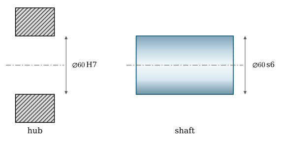
The hub of the shrink fit in the strain chapter has a bore of 60 H7 and its shaft is 60 s6, as the drawings of the two parts in Figure 9.10.9 specify. Find the limits of size and the range of interference.
Figure 9.10.9: The fit of Example 3 as it appears on the drawings: the bore of the hub is toleranced 60 H7, the shaft 60 s6.
At 60 mm the tolerance grades are IT7 = 30 µm and IT6 = 19 µm, and the fundamental deviation of s for sizes over 50 up to 65 mm is \(+53\) µm. With 9.10.8, 9.10.9 and 9.10.10,
The strain chapter used the largest interference, 72 µm, to find how hot the hub must be. The grip is set by the smallest, 23 µm, a third of it. Turning these into a pressure is the subject of the next two sections.
Stresses in a thick-walled cylinder
The hub of an interference fit is a ring with a pressure \(p\) in its bore, and the shaft a cylinder with the same pressure on its surface. Both are thick-walled, so the stress varies through the wall and the thin-walled formula \(\sigma = pr/t\) will not do. We solve the problem from the continuum equations, in polar coordinates, for a cylinder whose loads and shape do not depend on the angle \(\theta\). Then the only displacement is radial, \(u(r)\), and the stresses are the radial stress \(\sigma_r\) and the hoop stress \(\sigma_\theta\), with no shear.
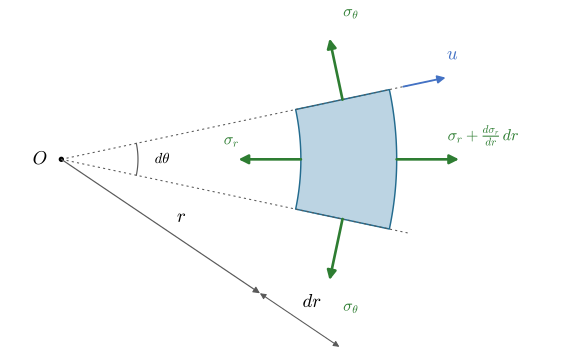
Figure 9.10.10: An element of the cylinder between the radii \(r\) and \(r + dr\) and the angle \(d\theta\), with the radial stress on its curved faces and the hoop stress on its flat ones. It moves out by the radial displacement \(u\).
Take the element of Figure 9.10.10, of unit length along the axis. The radial force on its outer face is \((\sigma_r + d\sigma_r)(r + dr)\,d\theta\), on its inner face \(\sigma_r r\,d\theta\), and the two hoop forces \(\sigma_\theta\,dr\) on the flat faces each have the radial component \(\sigma_\theta\,dr\,d\theta/2\) towards the axis. Radial equilibrium, after dividing by \(dr\,d\theta\) and dropping the second-order term, is
One equation and two unknown stresses: as in every statically indeterminate problem, the deformation must close the system. A point at the radius \(r\) moves out to \(r + u\). A line along the radius then stretches by \(du\) over \(dr\), and a circle of radius \(r\) grows from \(2\pi r\) to \(2\pi(r + u)\), so the strains are
The material constants have dropped out of the equation: the displacement of any cylinder loaded on its surfaces is a sum of a uniform stretch \(C_1 r\) and a term \(C_2/r\) that dies away from the axis. With it, 9.10.13 gives stresses of the form
\[
\sigma_r = A - \frac{B}{r^2}, \qquad \sigma_\theta = A + \frac{B}{r^2}
\tag{9.10.14}\]
the solution Lamé found in the 1850s, with \(A = EC_1/(1-\nu)\) and \(B = EC_2/(1+\nu)\). The sum \(\sigma_r + \sigma_\theta = 2A\) is the same at every radius. The constants follow from the pressures on the two surfaces.
Code
p, a, b = sp.symbols('p a b', positive=True) # pressure, inner and outer radiusC1, C2 = sp.symbols('C1 C2')u_gen = C1*rr + C2/rrsr_gen = (E/(1- nu**2)*(u_gen.diff(rr) + nu*u_gen/rr)).simplify()st_gen = (E/(1- nu**2)*(u_gen/rr + nu*u_gen.diff(rr))).simplify()# the hub: pressure p in the bore r = a, free outside at r = bhub = sp.solve([sr_gen.subs(rr, a) + p, sr_gen.subs(rr, b)], [C1, C2])sr_hub = p*a**2/(b**2- a**2)*(1- b**2/rr**2) # the textbook form ...st_hub = p*a**2/(b**2- a**2)*(1+ b**2/rr**2)assert sp.simplify(sr_hub - sr_gen.subs(hub)) ==0# ... is SymPy's solutionassert sp.simplify(st_hub - st_gen.subs(hub)) ==0u_hub = sp.simplify(u_gen.subs(hub).subs(rr, a))# a hollow shaft: pressure p outside at r = a, free in its bore r = a_ia_i = sp.symbols('a_i', positive=True)shaft = sp.solve([sr_gen.subs(rr, a) + p, sr_gen.subs(rr, a_i)], [C1, C2])u_shaft = sp.simplify(u_gen.subs(shaft).subs(rr, a))# the same displacements with the diameter ratios k_h = a/b and k_s = a_i/aR, k_h, k_s, E_h, E_s, nu_h, nu_s = sp.symbols(r'R kappa_h kappa_s E_h E_s nu_h nu_s', positive=True)u_h = R*p/E_h*((1+ k_h**2)/(1- k_h**2) + nu_h)u_s =-R*p/E_s*((1+ k_s**2)/(1- k_s**2) - nu_s)assert sp.simplify(u_hub.subs({a: R, b: R/k_h}) - u_h.subs({E_h: E, nu_h: nu})) ==0assert sp.simplify(u_shaft.subs({a: R, a_i: k_s*R}) - u_s.subs({E_s: E, nu_s: nu})) ==0
For the hub, with the pressure \(p\) in the bore of radius \(a\) and a free outer surface at \(b\), the stresses are
The radial stress runs from \(-p\) at the bore to zero outside. The hoop stress is tensile everywhere and largest at the bore: the pressure stretches the ring like a hoop on a barrel. With the diameter ratio \(\kappa_h = d/D = a/b\) of the hub, its value at the bore is
which is always larger than \(p\) and grows without bound as the hub gets thin, \(\kappa_h \to 1\). In a solid shaft \(B = 0\), since the displacement must stay finite on the axis, and the stress is the same everywhere, \(\sigma_r = \sigma_\theta = -p\): a solid shaft is squeezed uniformly. A hollow shaft with the bore ratio \(\kappa_s = d_i/d\) has its largest compressive hoop stress at the bore, \(2p/(1 - \kappa_s^2)\).
The interference pressure
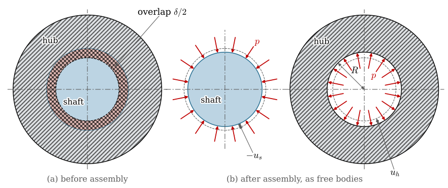
Before assembly the shaft is larger than the bore by the interference \(\delta\), which is \(\delta/2\) on the radius (Figure 9.10.11 a). After assembly both have the same radius \(R = d/2\). The pressure has opened the bore by \(u_h\) and squeezed the shaft by \(u_s\), which is negative, and the two together have taken up the overlap,
This is the compatibility condition of the joint, the same idea as the matching elongations in a statically indeterminate bar.
Figure 9.10.11: (a) Before assembly the shaft overlaps the bore by \(\delta/2\) on the radius, drawn grossly exaggerated. (b) After assembly, as free bodies: the pressure \(p\) squeezes the shaft in by \(-u_s\) and opens the bore by \(u_h\) until both have the radius \(R\).
The displacements at the contact radius \(R\) follow from the solutions of the last section. Written with the diameter ratios \(\kappa_h = d/D\) and \(\kappa_s = d_i/d\), and with each part in its own material, they are
the formula of the lecture notes and of Shigley [1, Eq. 7-39], written in diameters. The two terms in the denominator are the compliances of hub and shaft; each tells how much of the interference its part takes up, per unit of pressure. For hub and solid shaft of the same material the Poisson terms cancel and
\[
p = \frac{E\,\delta}{2d}\left(1 - \kappa_h^2\right)
\tag{9.10.18}\]
The pressure grows in proportion to the relative interference \(\delta/d\) and to the stiffness of the material. A thin hub, \(\kappa_h \to 1\), gives way and grips weakly; a hub twice as wide as the shaft already gives three quarters of the pressure an infinitely thick one would.
What the fit can carry
The pressure acts on the contact area \(\pi d L\) of a hub of length \(L\), so the normal force is \(p\pi d L\) and the largest friction force is \(\mu p\pi d L\). Acting at the radius \(d/2\), it carries the torque
\[
T = \frac{\pi}{2}\,\mu\,p\,d^2 L
\tag{9.10.19}\]
or, pointing along the shaft, the axial force
\[
F_a = \mu\,p\,\pi d L
\tag{9.10.20}\]
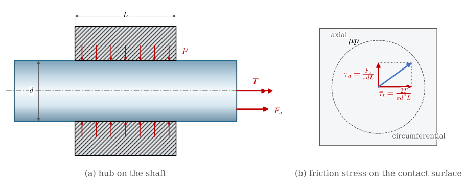
Figure 9.10.12: (a) The hub grips the shaft with the pressure \(p\) over the length \(L\); friction carries the torque \(T\) and the axial force \(F_a\). (b) On the contact surface the friction stresses from \(T\) and from \(F_a\) add as vectors, and their sum cannot exceed \(\mu p\): the friction circle.
When both act, the friction stresses they need are \(\tau_t = 2T/(\pi d^2 L)\) around the shaft and \(\tau_a = F_a/(\pi d L)\) along it, as Figure 9.10.12 shows. They add as vectors, since friction opposes the direction of slip, whatever it is, so the joint holds as long as
\[
\sqrt{F_a^2 + \left(\frac{2T}{d}\right)^2} \le \mu\,p\,\pi d L
\tag{9.10.21}\]
A helical gear pushes on its shaft with an axial force as well as a torque, and the axial force uses up part of the friction. A herringbone gear has two helices of opposite hand whose axial forces cancel, so all of the friction is left for the torque.
The design rule follows from 9.10.8: the torque the fit must carry is checked with the pressure from \(\delta_\min\), and the stresses in hub and shaft with the pressure from \(\delta_\max\). In the hub the critical point is the bore, where 9.10.15 gives a tensile hoop stress and a compressive radial stress; their von Mises stress is \(\sigma_\text{vM} = \sqrt{\sigma_\theta^2 - \sigma_\theta\sigma_r + \sigma_r^2}\). Near the ends of the hub the pressure rises above the value from 9.10.17, because the hub there is stiffened by nothing beyond it; Shigley [1] puts this stress concentration at seldom more than 2. It matters for fatigue of the shaft in bending, where the edge of the hub is where shafts with press-fitted hubs break.
Heating, cooling or pressing
A fit with a little interference is pressed together, cold, with a force of \(\mu p\pi d L\) from 9.10.20, worked out with \(\delta_\max\). A heavy fit needs a large press, and the pressing scrapes the surfaces, which smooths the peaks of the roughness and costs part of the interference. The alternative is to change the diameters with temperature: heat the hub until its bore is larger than the shaft, slide it on and let it cool. That is a shrink fit. The strain chapter found the temperature rise this takes,
\[
\Delta T = \frac{\delta_\max + c}{\alpha\,d}
\]
from 8.5.8, where \(c\) is the clearance wanted during assembly, commonly about a thousandth of the diameter. The hub’s size and the pressure do not enter, only the interference and the expansion coefficient. Figure 9.10.13 shows a shrink fit from beginning to end, with the numbers of Example 3.
Figure 9.10.13: Shrink-fitting the herringbone gear of Example 4 onto its shaft, 60 H7/s6 with the largest interference, 72 µm. The colour of the gear shows its temperature; real steel at 190 °C does not glow. The graph follows the bore: it grows with the temperature until the shaft slides in with a clearance of 50 µm, and on cooling it stops at the shaft. The dashed rest of the line is the shrinkage the shaft prevents, the interference that the contact pressure holds.
The shaft can be cooled instead. In liquid nitrogen at \(-196\) °C a steel shaft shrinks by the same formula, with a smaller mean \(\alpha\) since the expansion coefficient falls with temperature. Cooling is the choice when the hub must not be heated, for instance a gear whose hardness was set by tempering at a temperature of the same order, or a part with seals or plastic in it. For a heavy fit both are combined. Rolling bearings are mounted the same way, on an induction heater, and are not heated above about 120 °C, so that their hardened rings and their grease are not harmed.
Example 4: A herringbone gear shrunk onto its shaft
The herringbone gear of Figure 9.10.1, with \(N = 32\) teeth of module \(m = 4\) mm and a face width \(L = 40\) mm (see the herringbone chapter), is shrunk onto a solid 60 mm shaft with the fit 60 H7/s6 of Example 3. Both are of steel, \(E = 210\) GPa and \(\nu = 0.3\), and the friction coefficient of the dry shrink fit is \(\mu = 0.15\). The gear must transmit \(T = 400\) N·m (Figure 9.10.14). Find the range of contact pressure, the torque the fit carries, and the largest stress in the gear.
Figure 9.10.14: The herringbone gear of Example 4 on its shaft, in longitudinal section. The teeth above the root diameter \(D\) are left out of the hub when the pressure is computed.
The teeth stiffen the rim a little, but we take the gear as a ring out to its root diameter, \(D = m(N - 2.5) = 118\) mm, which errs on the safe side for the grip. The recipe is 9.10.18 for \(p\) at \(\delta_\min\) and \(\delta_\max\), 9.10.19 for the torque and 9.10.15 for the stresses at the bore.
The pressures for the smallest and the largest interference, the torque the fit carries at the smallest, and the hoop and von Mises stresses at the bore for the largest are
The fit carries 1010 N·m with the worst pair of parts, two and a half times the torque the gear transmits, and the best pair grips three times harder. The gear sees at most a von Mises stress of about 220 MPa at the bore, which a gear steel takes with a wide margin. The herringbone teeth push no axial force onto the shaft, so 9.10.21 adds nothing.
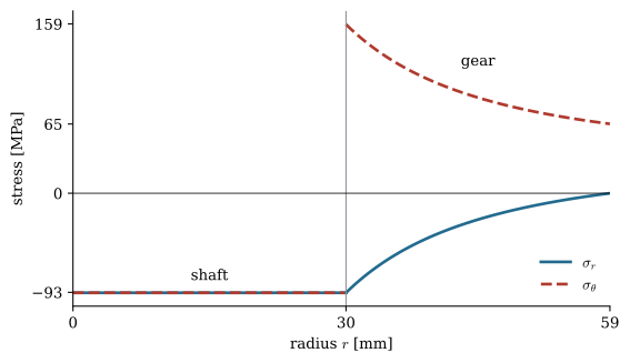
Figure 9.10.15 shows the stresses through shaft and gear for the largest interference. The shaft is squeezed uniformly; in the gear the radial stress falls from \(-p\) to zero and the hoop stress is largest at the bore.
Figure 9.10.15: Radial and hoop stress through the shaft and the gear of Example 4, for the largest interference of 60 H7/s6. The shaft is in uniform compression; the gear’s hoop stress is tensile and largest at the bore.
So far the interference was the difference of the measured diameters. A real surface has peaks, and when the parts are joined the peaks are flattened, so the interference that loads the parts is smaller. DIN 7190 [6] estimates the loss as \(0.8(R_{z,s} +
R_{z,h})\), an empirical rule in terms of the mean roughness depths of the two surfaces. For a ground shaft, \(R_z = 4\) µm, and a finely bored hub, \(R_z = 6.3\) µm, the loss is 8 µm, more than a third of \(\delta_\min\):
The factor of safety against slip falls from 2.5 to 1.6. For a gear with shock loads we would choose the next fit, H7/u6, whose smallest interference at 60 mm is 57 µm.
Example 5: Press, heat or cool
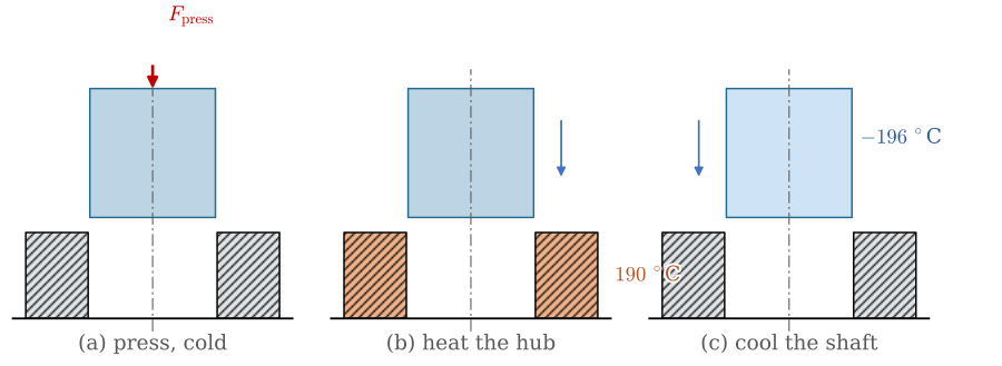
How large a press would the gear of Example 4 need, with lubricated surfaces and \(\mu = 0.10\)? How hot must it be for a shrink fit with a clearance of 50 µm, and would cooling the shaft in liquid nitrogen, with a mean \(\alpha = 9 \cdot 10^{-6}\) 1/°C down to \(-196\) °C, do instead? Figure 9.10.16 shows the three ways.
Figure 9.10.16: Three ways to assemble the fit of Example 5: (a) press the cold shaft in, (b) heat the gear so its bore opens, (c) cool the shaft so it shrinks.
The press must overcome the friction at the largest interference, 9.10.20 with \(p_\max\); the temperatures follow from 8.5.8.
Pressing takes 70 kN, the weight of seven tonnes, and scrapes the surfaces. Heating the gear to 190 °C, as in Figure 9.10.13, needs only an oven. Cooling the shaft alone gives a clearance of 45 µm, close to the 50 µm we asked for, and is the safer choice if the gear is case hardened.
TipIn industry: DIN 7190 and the induction heater
Interference fits are designed to DIN 7190 [6]. It is the calculation of this chapter, plane stress and Lamé’s equations, with the empirical parts written out: the smoothing loss \(0.8(R_{z,s} + R_{z,h})\), friction coefficients for each material pair that are lower for a pressed fit than for a shrunk one, a factor of safety against slip of at least about 1.5 and a check against yielding of the hub, and the temperature and clearance for assembly. Commercial calculators, and the fit calculators in CAD systems, work through the same standard. In the workshop, hubs and bearings are heated on induction heaters that stop at a set temperature, and large fits are taken apart with the oil injection method: oil pumped at high pressure into a groove in the bore opens the fit enough for the hub to slide off.
Fits in printed parts
A press fit in a printed plastic part behaves differently from one in steel, for two reasons. A printed hole is a grade or two coarser than a drilled one (Table 9.10.2), and it comes out undersize because the extruded plastic spreads into the hole, so the interference is unknown until the part is measured. And plastics creep: under the constant strain of an interference fit the stress relaxes over days, and the grip falls with it, faster when the part is warm. A printed hub pressed onto a steel shaft may hold on the bench and slip a week later. Printed designs therefore avoid relying on a small interference. A bore with crush ribs puts the interference into a few thin ribs that deform plastically, so the exact size of the hole matters less; a D-shaped or hexagonal bore locks the hub by its shape; and a brass insert pressed in with heat carries the load into a metal thread. How much grip remains after creep is a question for measurement, and one our lab tests on printed parts are set up to answer.
The ISO fits notebook
The notebook below draws the tolerance zones of Figure 9.10.7 (b) for any of the preferred fits of Table 9.10.1 at any basic size up to 400 mm, to scale, and works through 9.10.8 to 9.10.10 with the numbers. It uses the same mechanicskit.fits as the examples of this chapter.
The numbers are chosen so that each problem can be worked with the equations of the chapter and a calculator. Each answer is blurred until the mouse rests on it, or it is tapped.
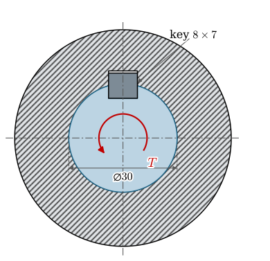
Problem 1: A keyed lever. A lever transmits \(T = 250\) N·m to a 30 mm shaft through a parallel key 8 × 7 with \(t_1 = 4\) mm and an effective length of 32 mm (Figure 9.10.17). The key has \(S_y = 350\) MPa. Find the shear stress in the key, the bearing stresses on its two sides, the factors of safety, and Moore’s strength ratio for the shaft.
Figure 9.10.17: The lever hub of Problem 1 in section.
Answer:\(F = 16.7\) kN, \(\tau = 65.1\) MPa, \(\sigma_{b,s} = 130\) MPa, \(\sigma_{b,h} = 174\) MPa; \(n = 3.1\) in shear and \(2.0\) in bearing on the hub side, which decides; \(e = 0.80\).
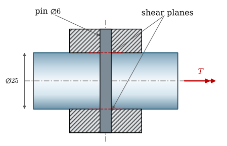
Problem 2: A shear pin. A cross pin of 6 mm diameter connects a hub to a 25 mm shaft (Figure 9.10.18) and is meant to shear when the drive jams. The pin has an ultimate shear strength of 420 MPa. At what torque does it shear? Which pin diameter would make the drive give way at 150 N·m, and what does a 4 mm pin give?
Figure 9.10.18: The pinned hub of Problem 2.
Answer:From 9.10.5, \(T = \tau_u \pi d_p^2 d/4 = 297\) N·m. For 150 N·m, \(d_p = 4.3\) mm; a 4 mm pin shears at 132 N·m.
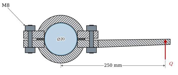
Problem 3: A clamped lever. A lever of 250 mm is clamped to a 20 mm shaft by two M8 bolts, each with a preload of 12 kN (Figure 9.10.19), and \(\mu = 0.15\). Find the torque the clamp carries in each of the three cases of Figure 9.10.5, and the force \(Q\) at the end of the lever that makes it slip in case I. The preload may be 25 % below its nominal value; what force should the lever be rated for?
Figure 9.10.19: The clamped lever of Problem 3.
Answer:\(M = 72\), \(91.7\) and \(113\) N·m. In case I the lever slips at \(Q = 288\) N; with the preload 25 % low, at \(216\) N.
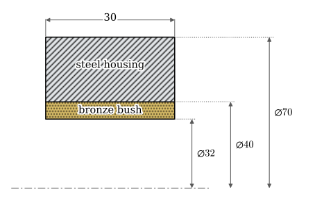
Problem 4: A pressed bush. A bronze bush (\(E = 110\) GPa, \(\nu = 0.34\)), 40 mm outside and 32 mm inside, is pressed into a steel housing (\(E = 210\) GPa, \(\nu = 0.3\)) of outer diameter 70 mm and length 30 mm with the fit 40 H7/p6 (Figure 9.10.20). Find the range of interference, the largest contact pressure, the press force with \(\mu = 0.10\), and how much the bore of the bush shrinks. Why is a pressed bush reamed after assembly?
Figure 9.10.20: The bush of Problem 4 in a half section.
Answer:At 40 mm, H7 is 0 to +25 µm and p6 +26 to +42 µm, so \(\delta = 1\) to 42 µm. With the bush as a hollow shaft, \(\kappa_s = 0.8\), and the housing \(\kappa_h = 0.571\), 9.10.17 gives \(p_\max = 21.4\) MPa, and the press force is 8.1 kN. The bore of the bush shrinks by \(2|u| = 4pb^2a/(E(b^2 - a^2)) = 35\) µm on the diameter, more than a whole H7 tolerance, so the bore is reamed to size after pressing.
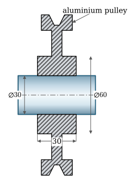
Problem 5: An aluminium pulley. An aluminium pulley (\(E = 70\) GPa, \(\nu = 0.33\), \(\alpha = 23 \cdot 10^{-6}\) 1/°C) with a hub of 60 mm outer diameter and 30 mm length is shrunk onto a steel shaft (\(\alpha = 12 \cdot 10^{-6}\) 1/°C) with the fit 30 H7/u6 (Figure 9.10.21), \(\mu = 0.15\). What torque does it carry at 20 °C? In service the whole assembly warms to 80 °C; what does it carry then, and at what temperature has the smallest interference vanished?
Figure 9.10.21: The pulley of Problem 5.
Answer:\(\delta_\min = 48 - 21 = 27\) µm gives \(p = 28.3\) MPa and \(T = 180\) N·m. At 80 °C the aluminium has grown \(30 \cdot 11 \cdot 10^{-6} \cdot 60 = 19.8\) µm more than the shaft, \(\delta_\min = 7.2\) µm, \(p = 7.5\) MPa and \(T = 48\) N·m. The grip is gone at \(20 + 27/(30 \cdot 11 \cdot 10^{-6}) = 102\) °C.
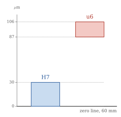
Problem 6: Heat or cool?Figure 9.10.22 shows the tolerance zones of 60 H7/u6 to scale. Read off the smallest and largest interference. How hot must a steel hub be for a clearance of 50 µm? A steel shaft cooled in liquid nitrogen shrinks with a mean \(\alpha = 9 \cdot 10^{-6}\) 1/°C from 20 to \(-196\) °C: is that enough on its own, and if not, how warm must the hub be as well?
Figure 9.10.22: The tolerance zones of Problem 6, in µm above 60 mm.
Answer:\(\delta_\min = 87 - 30 = 57\) µm and \(\delta_\max = 106\) µm. The hub alone needs \(\Delta T = 0.156/(12 \cdot 10^{-6} \cdot 60) = 217\) °C, to 237 °C. The cooled shaft shrinks 117 µm, a clearance of only 11 µm; heating the hub to 75 °C adds the missing 39 µm.
Further reading
Budynas and Nisbett [1 to 3-17, 7-7 and 7-8] derive the thick-walled cylinder and the press fit, size keys and give the metric preferred fits; their appendix tables are the source of the tolerance data in this chapter. ISO 286 [3,4] defines the tolerance system and tabulates every class, and DIN 7190 [6] is the design standard for interference fits, with the smoothing loss and the friction coefficients this chapter quoted. Björk [7] collects the formulas and the key and fit tables in the form Swedish engineers look them up.
Moore HF. The effect of keyways on the strength of shafts. Urbana, IL: University of Illinois Engineering Experiment Station; 1909.
[3]
ISO 286-1:2010 Geometrical product specifications (GPS) – ISO code system for tolerances on linear sizes – Part 1: Basis of tolerances, deviations and fits. Geneva, Switzerland: International Organization for Standardization; 2010.
[4]
ISO 286-2:2010 Geometrical product specifications (GPS) – ISO code system for tolerances on linear sizes – Part 2: Tables of standard tolerance classes and limit deviations for holes and shafts. Geneva, Switzerland: International Organization for Standardization; 2010.
[5]
ISO 2768-1:1989 General tolerances – Part 1: Tolerances for linear and angular dimensions without individual tolerance indications. Geneva, Switzerland: International Organization for Standardization; 1989.
[6]
DIN 7190-1:2017 Interference fits – Part 1: Calculation and design rules for cylindrical self-locking pressure fits. Berlin, Germany: Deutsches Institut für Normung; 2017.
[7]
Björk K. Formler och tabeller för mekanisk konstruktion. 9th ed. Spånga: Karl Björks förlag HB; 2022.