9.10 Belt Drives
“In treating of questions of pure mechanism, the centre line of a band is treated as being of invariable length.”
— W. J. M. Rankine, A Manual of Machinery and Millwork, 1869
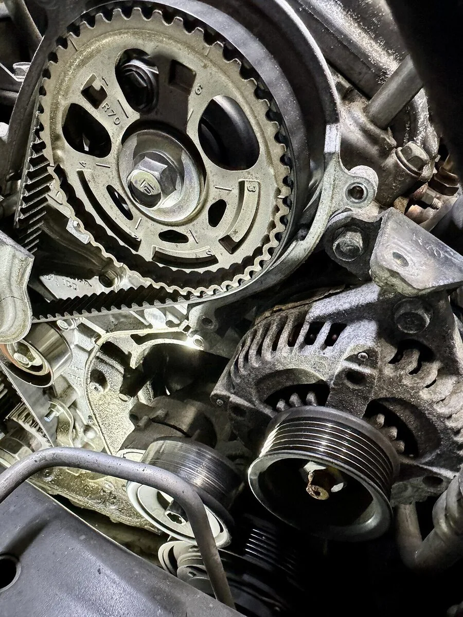
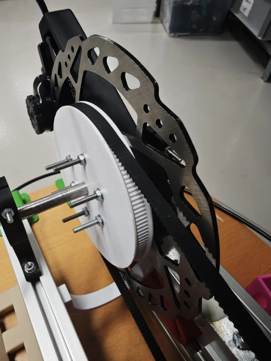
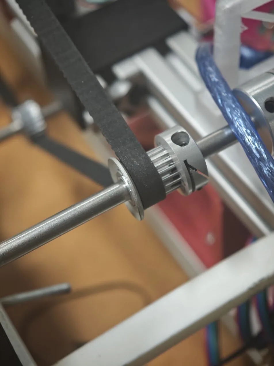
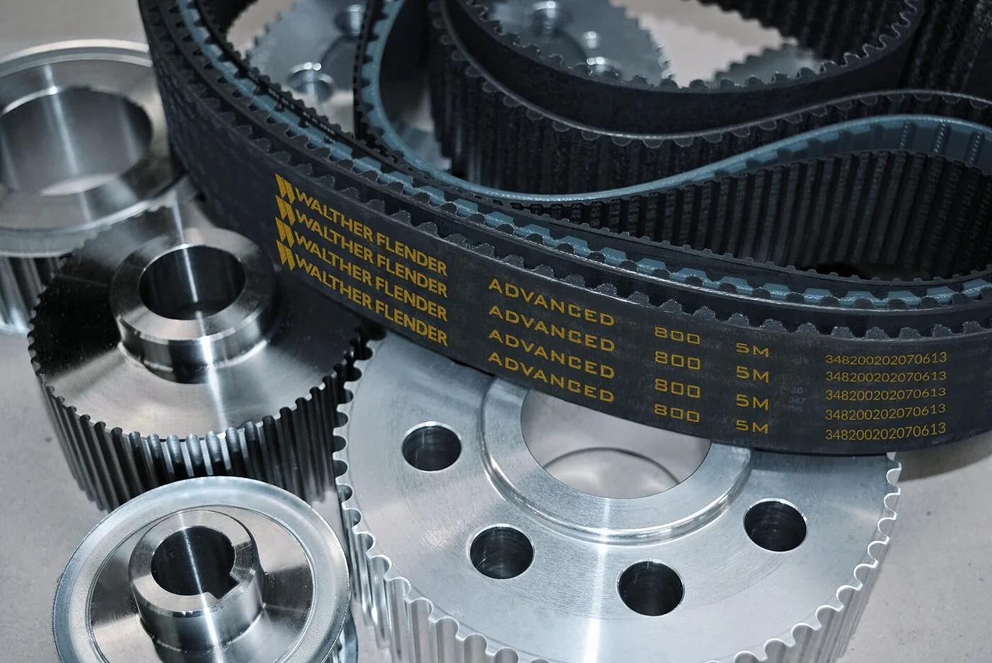
The reduction stage in Figure 9.10.1 runs on a GT2 toothed beltsv. kuggrem. The small pulleysv. remskiva on the driving shaft is bought; the large one is printed and bolted to the hub. Marketplace listings give the common 20 tooth GT2 pulley an outside diameter of 13.73 mm, and a pulley printed to that number will not take the belt: the right value is 12.22 mm. The difference lies inside the belt, at the tensile cord.
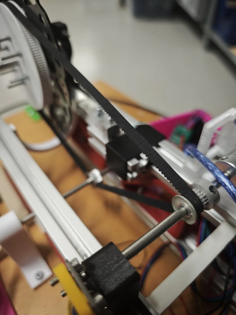
A belt drivesv. remdrift carries power between two shafts that are too far apart for a gear train and too poorly aligned for a coupling. It needs no lubrication, it absorbs the torque steps that chip a gear tooth, and it can be routed around obstacles that no pair of meshing wheels would tolerate. What it gives up is stiffness. Every belt drive puts a compliant member in the power path, and that member has to be held in tension.
Belt sections
Four cross sections cover nearly every belt drive, and they are best understood as successive answers to the same question: how do we get more force out of a given belt tension?

The flat beltsv. planrem is the oldest and the simplest. It presses on the pulley with whatever tension we install, and the friction it can develop follows directly from that normal force. It tolerates enormous centre distances, and it is the section that tracks itself: a belt running onto a crowned pulley is drawn towards the high point, so a flat belt drive needs no flanges to stay on.
The V beltsv. kilrem wedges into a groove instead of resting on a rim. The two flanks share the normal load, and because they are inclined, the same radial pull produces a much larger contact force; that is why V belts displaced flat belts in machinery. The round belt is the same idea in a form that can be twisted, which lets it drive shafts that are not parallel, at the price of a small contact patch and a correspondingly small torque capacity.
The toothed or synchronous belt abandons friction altogether. Its teeth seat in grooves cut to match, so the tangential force is carried in shear by the tooth flanks and not by friction on a smooth surface.
Friction belts: tension, torque and the slip limit
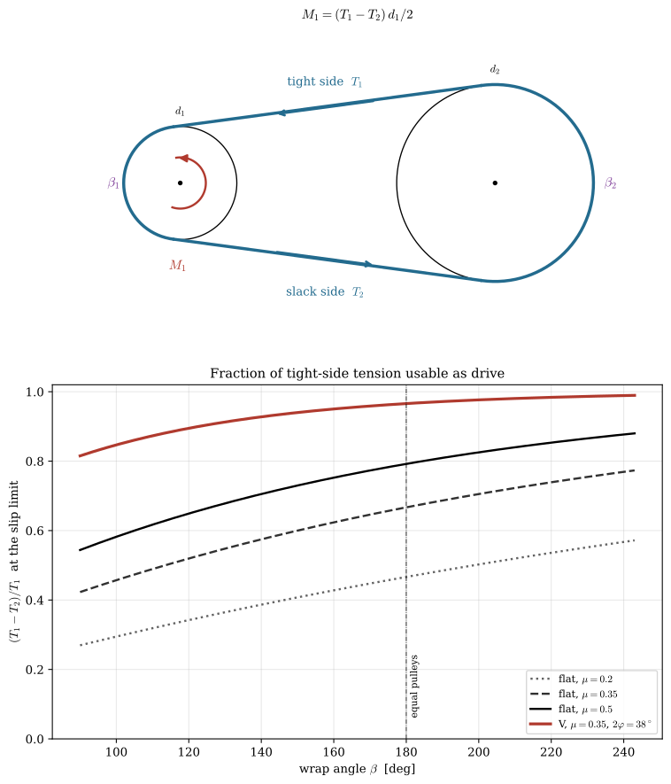
A belt wrapped on a pulley pulls on it from both sides. Writing \(T_1\) for the tension in the strand being drawn onto the driving pulley and \(T_2\) for the strand being paid off, moment equilibrium about the shaft axis gives the transmitted torque as the difference of the two,
\[ M_1 = \left(T_1 - T_2\right)\frac{d_1}{2} \tag{9.10.1}\]
and since a belt that neither stretches nor slips travels at the same speed \(v = \omega_1 d_1/2 = \omega_2 d_2/2\) everywhere, the transmitted power is
\[ P = \left(T_1 - T_2\right) v \tag{9.10.2}\]
Only the difference does work. The sum \(T_1 + T_2\) contributes nothing but bearing load, so extra tension installed to be safe loads the bearings permanently and buys nothing.
A friction belt cannot make that difference as large as we please. The bound comes from the capstan relation derived in the friction chapter, 5.6.3: a flexible band wrapped through an angle \(\beta\) on a surface of friction coefficient \(\mu\) sustains a ratio of at most \(e^{\mu\beta}\) between the tensions at its two ends. In the belt drive convention used here, where \(T_1\) is the larger of the two, that limit reads \(T_1/T_2 \le e^{\mu\beta_1}\), and eliminating \(T_2\) from 9.10.1 gives
\[ M_1 \le T_1 \frac{d_1}{2}\left(1 - e^{-\mu \beta_1}\right) \tag{9.10.3}\]
Three consequences follow. Capacity is set by the smaller pulley, because it has the smaller wrap angle and therefore reaches the limit first. Capacity grows only slowly with \(\mu\) and \(\beta\), since both appear inside a saturating exponential, so a belt that is marginal cannot be rescued by a grippier surface. And capacity is proportional to \(T_1\), which is the only term we can raise freely, at the cost of bearing load and belt life.
The V belt attacks the geometry instead. In a groove of included angle \(2\varphi\) the radial force is shared by two inclined flanks, so a radial pull \(\mathrm{d}N_r\) produces a total flank normal force \(\mathrm{d}N_r/\sin\varphi\) and the capstan relation applies with an effective coefficient
\[ \mu' = \frac{\mu}{\sin\varphi} \tag{9.10.4}\]
At the usual \(2\varphi = 38^\circ\) this multiplies the friction by about three, more than any surface treatment can give. The same wedging is why a V belt has to be pulled out of its groove as it leaves the pulley, and why it will not run at small pulley diameters.
Two effects cut into the available capacity as speed rises. The belt is a rotating mass, so a length \(\mathrm{d}s\) on the arc needs a centripetal force that the belt tension itself must supply, which subtracts a centrifugal tension \(T_c = \mu_L v^2\) from the useful part, with \(\mu_L\) the belt mass per unit length.
Because the belt is elastic and its tension falls as it travels around the driving pulley from the tight side to the slack side, it shortens as it goes, so it creeps backwards relative to the pulley surface. Creep is unavoidable and typically loses one to two percent of speed. It is also the reason a friction belt can never be used where the output must keep phase with the input.
Code
def open_belt(r1, r2, C):
    # Tangent points for an open belt with the small pulley at the origin.
    a = np.arcsin((r2 - r1) / C)
    n = np.array([-np.sin(a), np.cos(a)])
    return (a, r1 * n, np.array([C, 0.0]) + r2 * n,
            r1 * n * [1, -1], np.array([C, 0.0]) + r2 * n * [1, -1])


def draw_belt(ax, r1, r2, C, lw=2.6, color=BLUE):
    a, P1u, P2u, P1l, P2l = open_belt(r1, r2, C)
    ax.plot([P1u[0], P2u[0]], [P1u[1], P2u[1]], color=color, lw=lw, solid_capstyle='butt')
    ax.plot([P1l[0], P2l[0]], [P1l[1], P2l[1]], color=color, lw=lw, solid_capstyle='butt')
    th = np.linspace(np.pi/2 + a, 3*np.pi/2 - a, 200)
    ax.plot(r1*np.cos(th), r1*np.sin(th), color=color, lw=lw)
    th = np.linspace(-(np.pi/2 + a), np.pi/2 + a, 300)
    ax.plot(C + r2*np.cos(th), r2*np.sin(th), color=color, lw=lw)
    return a


fig, (ax1, ax2) = plt.subplots(2, 1, figsize=(8, 9.5))

r1, r2, Cd = 1.15, 2.0, 6.4
t = np.linspace(0, 2*np.pi, 400)
for cx, r in ((0.0, r1), (Cd, r2)):
    ax1.plot(cx + r*np.cos(t), r*np.sin(t), 'k-', lw=1.0)
    ax1.plot([cx], [0], 'ko', ms=3)
a = draw_belt(ax1, r1, r2, Cd)

for s, lab, dy in ((1, r"tight side  $T_1$", 0.45), (-1, r"slack side  $T_2$", -0.75)):
    y = lambda x: s*(r1*np.cos(a) + x*np.tan(a))
    x0, x1 = (Cd*0.30, Cd*0.62) if s > 0 else (Cd*0.62, Cd*0.30)
    ax1.annotate("", xy=(x1, y(x1)), xytext=(x0, y(x0)),
                 arrowprops=dict(arrowstyle='<-', lw=2.0, color=BLUE))
    ax1.text(Cd*0.46, y(Cd*0.46) + dy, lab, ha='center', color=BLUE, fontsize=10)

th = np.linspace(-0.6*np.pi, 0.55*np.pi, 60)
ax1.plot(0.52*np.cos(th), 0.52*np.sin(th), color=RED, lw=1.8)
ax1.annotate("", xy=(0.52*np.cos(th[-1]), 0.52*np.sin(th[-1])),
             xytext=(0.52*np.cos(th[-8]), 0.52*np.sin(th[-8])),
             arrowprops=dict(arrowstyle='-|>', lw=1.8, color=RED, mutation_scale=13))
ax1.text(-0.05, -1.75, r"$M_1$", color=RED, ha='center', fontsize=11)
ax1.text(0, r1 + 0.25, r"$d_1$", ha='center', fontsize=9)
ax1.text(Cd, r2 + 0.25, r"$d_2$", ha='center', fontsize=9)
ax1.text(-1.35, 0, r"$\beta_1$", ha='center', va='center', fontsize=11, color='#7D3C98')
ax1.text(Cd + 2.35, 0, r"$\beta_2$", ha='center', va='center', fontsize=11, color='#7D3C98')
ax1.set_xlim(-2.6, Cd + 3.4); ax1.set_ylim(-3.2, 3.2)
ax1.set_aspect('equal'); ax1.axis('off')
ax1.set_title(r"$M_1 = (T_1-T_2)\,d_1/2$", fontsize=11)

beta = np.linspace(np.pi/2, 1.35*np.pi, 300)
for mu, ls in ((0.20, ':'), (0.35, '--'), (0.50, '-')):
    ax2.plot(np.degrees(beta), 1 - np.exp(-mu*beta), ls, lw=1.8, color='k',
             alpha=0.35 + 1.3*mu, label=fr"flat, $\mu={mu}$")
mu_eff = 0.35/np.sin(np.radians(19))
ax2.plot(np.degrees(beta), 1 - np.exp(-mu_eff*beta), '-', lw=2.4, color=RED,
         label=r"V, $\mu=0.35$, $2\varphi=38^\circ$")
ax2.axvline(180, color='k', lw=0.6, ls='-.')
ax2.text(181, 0.06, "equal pulleys", fontsize=8, rotation=90, va='bottom')
ax2.set_xlabel(r"wrap angle $\beta$  [deg]")
ax2.set_ylabel(r"$(T_1-T_2)/T_1$  at the slip limit")
ax2.set_ylim(0, 1.02); ax2.grid(alpha=0.3)
ax2.legend(fontsize=8.5, loc='lower right')
ax2.set_title("Fraction of tight-side tension usable as drive", fontsize=11)
plt.tight_layout()
plt.show()Drive layouts
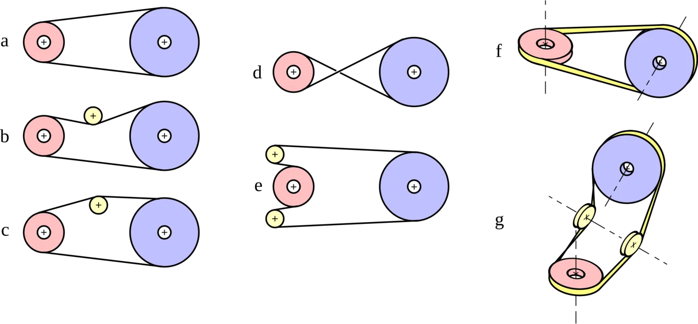
An idlersv. spännrulle pressed against the slack side takes up tension without moving either shaft, and where it presses decides what it does to the wrap. An outside idler pushes the span into the loop, as in (b) and (e); placed near the small pulley it increases the wrap angle there, which 9.10.3 rewards directly. An inside idler, as in (c), pushes the span outwards and reduces the wrap.
Crossing the belt reverses the output and gives close to \(\pi\) of wrap on both pulleys, but the belt rubs against itself where the strands cross, so it is confined to slow flat-belt drives. The quarter turn transmits between shafts at right angles and only works if each strand enters its pulley in the plane of that pulley, which fixes the direction of rotation and makes the drive non-reversible.
A toothed belt narrows these options. An inside idler runs on the teeth, and Gates recommends a grooved one up to 40 grooves and a flat one only above that. An outside idler runs on the back; it should be flat, at least 1.3 times the smallest recommended sprocket, and it bends the belt backwards, which the same manual lists as a cause of cracking, noise and tooth shear [1]. Tension in a synchronous drive is therefore usually taken up by moving a shaft, and an idler, where one is needed, goes inside on the slack side.
Synchronous belts
Where the output has to hold a fixed angular relationship to the input, the belt must be given teeth. The ratio is then fixed exactly by the tooth counts, and creep disappears.
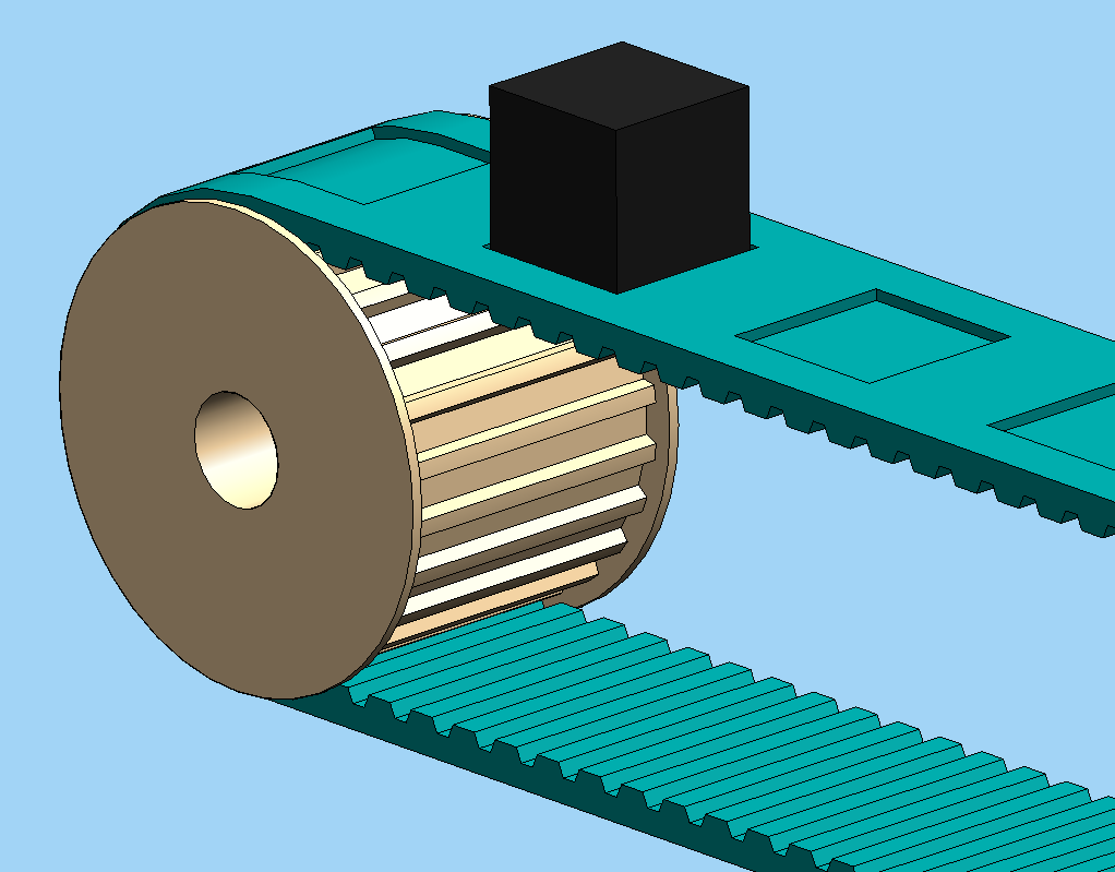
The archetypal application is the camshaft drive of a combustion engine, where losing synchronisation by a single tooth is enough to put a piston through a valve. The same requirement appears wherever a position, and not only a speed, has to be reproduced at the output, and every printer, plotter and pick-and-place head therefore runs on toothed belts.
Trapezoidal and curvilinear teeth
The imperial series carries a trapezoidal tooth, the oldest synchronous form. ISO 5296 [2] fixes seven pitch codes running from MXL at \(2.032\) mm to XXH at \(31.75\) mm, and tabulates for each the tooth angle \(2\beta\), the width \(s\) at the tooth root, the tooth height \(h_t\), and the fillet radii. The tooth is easy to cut and easy to draw, but it has two weaknesses. Load concentrates where the straight flank meets the belt body, and the tooth has to deflect as it rolls into and out of the groove, which shows as noise and as backlash under reversing load.
The curvilinear profiles that replaced it put a rounded tooth into a rounded groove. Contact spreads over the whole flank instead of concentrating at the root, so the same belt width carries more torque, and the tooth seats with less radial motion. ISO 13050 [3] standardises fourteen such profiles across four systems, G, H, R and S, corresponding to the Gates PowerGrip GT, HTD, RPP and STD families.
Code
def trap_tooth(c, p, ht, half_angle_deg, land_frac):
    ta = np.tan(np.radians(half_angle_deg))
    root = p*land_frac/2
    tip = root + ht*ta
    return ([c - tip, c - root, c + root, c + tip], [0.0, -ht, -ht, 0.0])


def curv_tooth(c, p, ht):
    th = np.linspace(0, np.pi, 80)
    R = p*0.36
    return (list(c - R*np.cos(th)), list(-ht*np.sin(th)))


def belt_strip(p, ht, hs, n, kind, x0):
    xs, ys = [x0], [0.0]
    for k in range(n):
        c = x0 + (k + 0.5)*p
        tx, ty = trap_tooth(c, p, ht, 25, 0.273) if kind == 'trap' else curv_tooth(c, p, ht)
        xs += tx
        ys += ty
    xs += [x0 + n*p, x0 + n*p, x0]
    ys += [0.0, hs - ht, hs - ht]
    return np.array(xs), np.array(ys)


fig, ax = plt.subplots(figsize=(10, 4.0))
span = 20.4
rows = [("XL   trapezoidal", 5.08, 1.27, 2.3, 'trap', 3.0),
        ("GT2   curvilinear", 2.00, 0.76, 1.52, 'curv', -2.4)]
for title, p, ht, hs, kind, y0 in rows:
    n = int(span // p)
    xs, ys = belt_strip(p, ht, hs, n, kind, -n*p/2)
    ax.fill(xs, ys + y0, color='#333333', lw=0)
    ax.plot([-span/2 - 0.5, span/2 + 0.5], [y0 + 0.12, y0 + 0.12], '--', color=RED, lw=1.0)
    ax.text(-span/2 - 0.9, y0 + 1.05, title, fontsize=10.5, ha='left')
    ax.text(span/2 + 0.9, y0 + 0.12, "cord", color=RED, fontsize=8.5, va='center')
    xa = -n*p/2 + 0.5*p
    ax.annotate("", xy=(xa, y0 - ht - 0.45), xytext=(xa + p, y0 - ht - 0.45),
                arrowprops=dict(arrowstyle='<->', lw=1.0))
    ax.text(xa + p/2, y0 - ht - 1.05, fr"$p={p}$", ha='center', fontsize=9)
    ax.annotate("", xy=(span/2 + 2.6, y0), xytext=(span/2 + 2.6, y0 - ht),
                arrowprops=dict(arrowstyle='<->', lw=1.0))
    ax.text(span/2 + 2.9, y0 - ht/2, fr"$h_t={ht}$", va='center', fontsize=9)
    ax.annotate("", xy=(span/2 + 5.4, y0 + hs - ht), xytext=(span/2 + 5.4, y0 - ht),
                arrowprops=dict(arrowstyle='<->', lw=1.0))
    ax.text(span/2 + 5.7, y0 + (hs - 2*ht)/2, fr"$h_s={hs}$", va='center', fontsize=9)

ax.plot([-span/2, -span/2 + 5], [-4.6, -4.6], 'k-', lw=2)
ax.text(-span/2 + 2.5, -5.2, "5 mm", ha='center', fontsize=9)
ax.set_xlim(-span/2 - 1.5, span/2 + 9.5)
ax.set_ylim(-5.8, 4.9)
ax.set_aspect('equal'); ax.axis('off')
plt.tight_layout()
plt.show()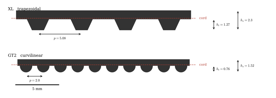
The smallest pitch ISO 13050 standardises is \(3\) mm. The \(2\) mm curvilinear system sold everywhere as GT2 or 2GT is not in the standard. Gates catalogues it as the 2MR PowerGrip GT profile, and the parts sold as 2GT are dimensionally compatible copies of it. An XL groove can therefore be looked up in a public document, while a GT2 groove has to be taken from a supplier drawing. This is the main reason to prefer a generated or purchased GT2 pulley over one drawn from first principles.
The sections that come up most often are collected below. Belt tooth heights \(h_t\) for the imperial sections are the nominal values of ISO 5296 Table 2; belt thickness \(h_s\) and the curvilinear tooth heights are from supplier catalogues, and the pitch line differential \(U\) is derived from published pulley tables in Pitch line differential.
| Section | Profile | Pitch \(p\) | Tooth height \(h_t\) | Belt thickness \(h_s\) | \(U\) |
|---|---|---|---|---|---|
| MXL | trapezoidal | 2.032 mm | 0.51 mm | 1.14 mm | 0.254 mm |
| XXL | trapezoidal | 3.175 mm | 0.76 mm | – | 0.254 mm |
| XL | trapezoidal | 5.080 mm | 1.27 mm | 2.30 mm | 0.254 mm |
| L | trapezoidal | 9.525 mm | 1.91 mm | 3.56 mm | 0.381 mm |
| H | trapezoidal | 12.700 mm | 2.29 mm | 4.32 mm | 0.686 mm |
| GT2 2MR | curvilinear | 2.00 mm | 0.76 mm | 1.52 mm | 0.254 mm |
| GT2 3MR | curvilinear | 3.00 mm | 1.14 mm | 2.41 mm | 0.381 mm |
| GT2 8M | curvilinear | 8.00 mm | 3.28 mm | 5.59 mm | 0.686 mm |
| HTD 5M | curvilinear | 5.00 mm | 2.08 mm | 3.81 mm | 0.572 mm |
Geometry
Pitch diameter
The tensile cords sit a little above the root of the belt teeth, and the circle those cords follow when the belt is wrapped on a pulley is the pitch circle. That circle, not the metal, is what the kinematics see. Since \(N\) teeth at pitch \(p\) have to fit around it,
\[ d_p = \frac{N p}{\pi} \tag{9.10.5}\]
A 20 tooth GT2 pulley therefore has \(d_p = 20 \cdot 2/\pi = 12.732\) mm, and belt travel per revolution is exactly \(Np = 40\) mm. The speed ratio follows from the requirement that both pulleys move the same length of belt,
\[ i = \frac{\omega_1}{\omega_2} = \frac{d_2}{d_1} = \frac{N_2}{N_1} \tag{9.10.6}\]
which, unlike the ratio of a friction drive, is exact.
Pitch line differential
The pulley we actually machine or print is smaller than its pitch circle, because the cord rides above the pulley land by a distance \(U\), the pitch line differential,
\[ d_o = d_p - 2U \tag{9.10.7}\]
so the 20 tooth GT2 pulley above turns a pitch diameter of \(12.732\) mm into an outside diameter of \(12.224\) mm.
Code
def pulley_outline(N, do, ht, npts=4000):
    # Grooved pulley outline: land at d_o/2, grooves cut inward by h_t.
    t = np.linspace(0, 2*np.pi, npts)
    s = (N*t/(2*np.pi)) % 1.0
    u = np.clip((np.abs(s - 0.5) - 0.20)/0.30, 0, 1)
    return t, do/2 - ht*np.sqrt(np.clip(1 - u**2, 0, 1))


fig, (ax1, ax2) = plt.subplots(2, 1, figsize=(8, 10.5))
p, N, U, ht = 2.0, 20, 0.254, 0.76
dp, do = N*p/np.pi, N*p/np.pi - 2*U

t, r = pulley_outline(N, do, ht)
ax1.fill(r*np.cos(t), r*np.sin(t), color=GREY, lw=0)
ax1.plot(r*np.cos(t), r*np.sin(t), 'k-', lw=0.9)
tc = np.linspace(0, 2*np.pi, 500)
ax1.plot(dp/2*np.cos(tc), dp/2*np.sin(tc), '--', color=RED, lw=1.4)
ax1.plot(do/2*np.cos(tc), do/2*np.sin(tc), '-.', color=BLUE, lw=1.3)
ax1.plot([0], [0], 'k+', ms=9)
ax1.annotate("", xy=(0, 0), xytext=(dp/2*np.cos(np.radians(62)), dp/2*np.sin(np.radians(62))),
             arrowprops=dict(arrowstyle='<->', lw=1.0, color=RED))
ax1.text(0.7, 3.6, r"$d_p/2$", color=RED, fontsize=11)
ax1.annotate("", xy=(0, 0), xytext=(do/2*np.cos(np.radians(-52)), do/2*np.sin(np.radians(-52))),
             arrowprops=dict(arrowstyle='<->', lw=1.0, color=BLUE))
ax1.text(2.5, -2.9, r"$d_o/2$", color=BLUE, fontsize=11)
ax1.set_title(fr"20T GT2:  $d_p={dp:.3f}$ mm,  $d_o={do:.3f}$ mm", fontsize=11)
ax1.set_xlim(-8, 8); ax1.set_ylim(-8.6, 8.6)
ax1.set_aspect('equal'); ax1.axis('off')


def groove(x, p, ht, phase=0.0):
    s = ((x/p) + phase) % 1.0
    u = np.clip((np.abs(s - 0.5) - 0.18)/0.32, 0, 1)
    return -ht*np.sqrt(np.clip(1 - u**2, 0, 1))


Udraw = 0.34                       # drawn larger than life so that it is visible
xs = np.linspace(-4.1, 4.1, 2600)
yg = groove(xs, p, ht, 0.5)
ax2.fill_between(xs, yg, -2.2, color=GREY, lw=0, zorder=1)
ax2.plot(xs, yg, 'k-', lw=1.5, zorder=4)
mb = np.abs(xs) < 2.4
yb = groove(xs, p, ht*0.90, 0.5) + 0.05
ax2.fill_between(xs[mb], yb[mb], 0.80, color='#333333', lw=0, zorder=2)
ax2.plot([-4.1, 4.0], [0, 0], '-.', color=BLUE, lw=1.7, zorder=6)
ax2.plot([-4.1, 4.0], [Udraw, Udraw], '--', color=RED, lw=1.9, zorder=6)
ax2.annotate("", xy=(3.3, 0), xytext=(3.3, Udraw), zorder=7,
             arrowprops=dict(arrowstyle='<->', lw=1.8, color='g',
                             shrinkA=0, shrinkB=0, mutation_scale=11))
ax2.text(3.55, Udraw/2, r"$U$", color='g', fontsize=15, va='center')
ax2.text(-4.05, 1.35, r"pitch line $d_p$: the tensile cord", color=RED, fontsize=10.5)
ax2.text(-4.05, -1.85, r"tip circle $d_o$: the pulley land", color=BLUE, fontsize=10.5)
ax2.annotate("", xy=(-3.35, Udraw + 0.03), xytext=(-3.1, 1.25), zorder=7,
             arrowprops=dict(arrowstyle='->', lw=1.0, color=RED))
ax2.annotate("", xy=(-3.6, -0.04), xytext=(-3.3, -1.7), zorder=7,
             arrowprops=dict(arrowstyle='->', lw=1.0, color=BLUE))
ax2.set_xlim(-4.3, 4.4); ax2.set_ylim(-2.3, 2.0)
ax2.set_aspect('equal'); ax2.axis('off')
ax2.set_title(r"Detail: the cord rides $U$ above the land ($U$ exaggerated)", fontsize=10.5)
plt.tight_layout()
plt.show()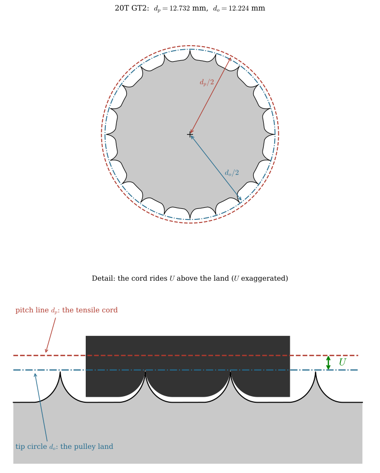
NoteWhere the values of \(U\) come from
\(U\) is not tabulated in most belt catalogues, but it can be recovered exactly from any published table of pitch and outside diameters, because 9.10.7 says the difference between the two columns is \(2U\) and is the same for every tooth count in a section. Reading two widely separated rows from each table checks both the value and the claim that it is constant.
Code
# (section, teeth, pitch diameter, outside diameter) in inches, read from published
# pulley tables. Two rows per section, far apart, to confirm the difference is constant.
rows = [("MXL",     10, 0.255, 0.235), ("MXL",     50, 1.273, 1.253),
        ("XL",      10, 0.637, 0.617), ("XL",      50, 3.183, 3.163),
        ("L",       10, 1.194, 1.164), ("L",       50, 5.968, 5.938),
        ("H",       50, 7.958, 7.904), ("H",       51, 8.117, 8.063),
        ("GT2 2MR", 12, 0.301, 0.281), ("GT2 2MR", 50, 1.253, 1.233),
        ("GT2 8M",  50, 5.013, 4.959), ("GT2 8M",  51, 5.113, 5.059),
        ("HTD 5M",  13, 0.815, 0.770), ("HTD 5M",  50, 3.133, 3.088)]

U = {}
for name, N_, PD, OD in rows:
    U.setdefault(name, set()).add(round((PD - OD)/2 * 25.4, 4))

# a section whose two rows give one value has a constant differential
U_found = {sp.Symbol(fr"U_{{\text{{{k}}}}}"): sp.Float(sorted(v)[0], 4)
           for k, v in U.items() if len(v) == 1}
The differential of each section, in millimetres:
\[ \begin{aligned} U_{\text{MXL}} &= 0.254 \\[9.0pt] U_{\text{XL}} &= 0.254 \\[9.0pt] U_{\text{L}} &= 0.381 \\[9.0pt] U_{\text{H}} &= 0.6858 \\[9.0pt] U_{\text{GT2 2MR}} &= 0.254 \\[9.0pt] U_{\text{GT2 8M}} &= 0.6858 \\[9.0pt] U_{\text{HTD 5M}} &= 0.5715 \end{aligned} \]
Every section returns a single value from both rows, so the differential is a property of the section and not of the pulley. The imperial sections come out at \(0.010\) in, \(0.015\) in and \(0.027\) in for the sizes above, and the \(2\) mm and \(8\) mm curvilinear profiles share the values of MXL and H exactly.
WarningCheck which differential you have been given
Some sources tabulate the radial offset \(U\) and write \(d_o = d_p - 2U\), while others tabulate the diametral difference \(d_p - d_o\) directly and subtract it once. The two figures differ by a factor of two, and quoting one where the other is meant gives a wrong pulley.
Marketplace listings and generated buying guides go further. Values of the form “GT2 20T outside diameter 13.73 mm” lie 1.00 mm above the pitch diameter of 12.73 mm, where the land has to lie 0.51 mm below it, so the sign of the correction is wrong as well as its size. Whichever number you are handed, check it against a published pitch and outside diameter table before committing a pulley to a print or to a cutter.
Belt length and centre distance
For two pulleys of pitch diameter \(d_1 \le d_2\) at centre distance \(C\), the belt leaves each pulley along a common tangent. The radius to a tangent point is perpendicular to that tangent, so the two radii are parallel, the difference \(d_2/2 - d_1/2\) is taken up across the centre distance, and the tangent is inclined to the line of centres by
\[ \sin\alpha = \frac{d_2 - d_1}{2C} \tag{9.10.8}\]
The wrap angles follow immediately as \(\beta_1 = \pi - 2\alpha\) on the small pulley and \(\beta_2 = \pi + 2\alpha\) on the large one, and each free span has length \(C\cos\alpha\).
Code
fig, ax = plt.subplots(figsize=(9.5, 4.6))
r1, r2, Cd = 1.1, 2.3, 7.0
t = np.linspace(0, 2*np.pi, 400)
for cx, r in ((0.0, r1), (Cd, r2)):
    ax.plot(cx + r*np.cos(t), r*np.sin(t), 'k--', lw=0.9)
    ax.plot([cx], [0], 'ko', ms=3.5)
a, P1u, P2u, P1l, P2l = open_belt(r1, r2, Cd)
draw_belt(ax, r1, r2, Cd)

ax.plot([0, Cd], [0, 0], 'k-.', lw=0.7)
ax.annotate("", xy=(0, -3.5), xytext=(Cd, -3.5), arrowprops=dict(arrowstyle='<->', lw=1.1))
ax.text(Cd/2, -3.95, r"$C$", ha='center', fontsize=11)
for x in (0, Cd):
    ax.plot([x, x], [-0.15, -3.65], 'k:', lw=0.6)
ax.plot([0, P1u[0]], [0, P1u[1]], 'k-', lw=0.8)
ax.plot([Cd, P2u[0]], [0, P2u[1]], 'k-', lw=0.8)
ax.text(P1u[0]*0.55 - 0.75, P1u[1]*0.55, r"$d_1/2$", fontsize=9.5)
ax.text(Cd + (P2u[0] - Cd)*0.5 - 0.95, P2u[1]*0.5, r"$d_2/2$", fontsize=9.5)

xi = P1u[0] - P1u[1]/np.tan(a)
ax.plot([xi, P2u[0] + 0.9], [0, (P2u[0] + 0.9 - xi)*np.tan(a)], 'k:', lw=0.7)
ax.plot([xi, Cd + 3.0], [0, 0], 'k:', lw=0.7)
aa = np.linspace(0, a, 60)
ax.plot(xi + 2.6*np.cos(aa), 2.6*np.sin(aa), color=RED, lw=1.6)
ax.text(xi + 2.9, 0.62, r"$\alpha$", color=RED, fontsize=13)
ax.text(xi + 0.55, -1.45, r"$\sin\alpha=\dfrac{d_2-d_1}{2C}$", color=RED, fontsize=11)
ax.text(-2.1, 0, r"$\beta_1$", ha='center', va='center', fontsize=12, color='#7D3C98')
ax.text(Cd + 3.25, 0, r"$\beta_2$", ha='center', va='center', fontsize=12, color='#7D3C98')
ax.annotate(r"free span $C\cos\alpha$", xy=((P1u[0] + P2u[0])/2, (P1u[1] + P2u[1])/2),
            xytext=(Cd*0.34, 3.5), fontsize=10, color=BLUE,
            arrowprops=dict(arrowstyle='->', lw=1.0, color=BLUE))
ax.set_xlim(-7.4, Cd + 4.6); ax.set_ylim(-4.9, 4.3)
ax.set_aspect('equal'); ax.axis('off')
plt.tight_layout()
plt.show()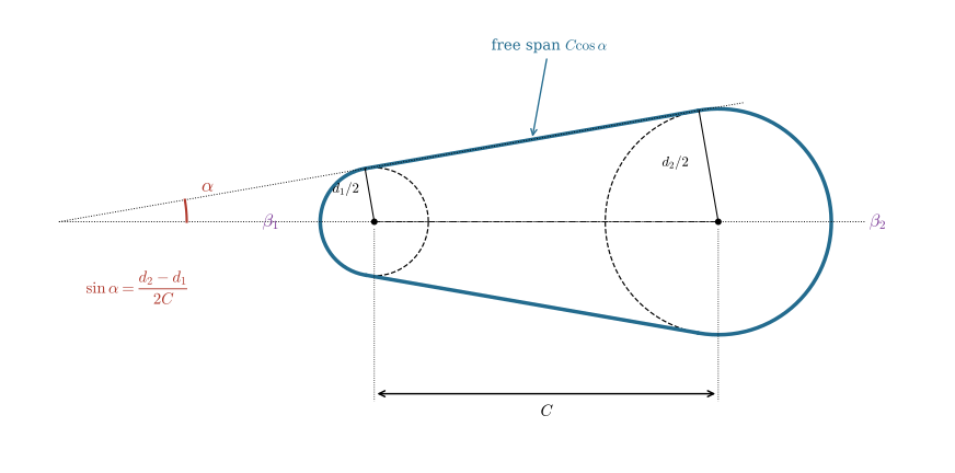
Adding the two tangents to the two arcs gives the pitch length,
\[ L = 2C\cos\alpha + \frac{d_2}{2}\left(\pi + 2\alpha\right) + \frac{d_1}{2}\left(\pi - 2\alpha\right) \tag{9.10.9}\]
The familiar approximation
\[ L \approx 2C + \frac{\pi}{2}\left(d_1 + d_2\right) + \frac{\left(d_2 - d_1\right)^2}{4C} \]
is what 9.10.9 becomes when \(\alpha\) is small, and it is good to well under a millimetre for the ratios met in practice.
In practice we never solve 9.10.9 for \(C\) and then order a belt to suit, because belts come only in whole numbers of teeth, \(L = N_b\,p\). We choose a stock belt, invert 9.10.9 numerically for the centre distance it implies, and give the mounting enough adjustment to absorb the difference.
Example 1: Centre distance for a 90XL belt
The imperial designation states pitch length in tenths of an inch, so a 90XL belt is \(9.000\) in \(= 228.60\) mm of pitch length, and at \(p = 5.08\) mm that is \(45\) teeth, a value ISO 5296 Table 3 lists directly [2]. Driving a 30 tooth pulley from a 15 tooth pulley with that belt fixes the centre distance.
Code
p_XL = sp.Rational(508, 100)                       # 5.08 mm, exact by definition
N1, N2 = 15, 30
d1, d2 = N1*p_XL/sp.pi, N2*p_XL/sp.pi
C_min = (d1 + d2)/2                                # pulleys touch below this

Cs = sp.Symbol('C', positive=True)
alpha = sp.asin((d2 - d1)/(2*Cs))
L_expr = 2*Cs*sp.cos(alpha) + d2/2*(sp.pi + 2*alpha) + d1/2*(sp.pi - 2*alpha)

C_of = {Nb: sp.nsolve(L_expr - Nb*p_XL, Cs, 50) for Nb in (45, 40)}
Solving 9.10.9 numerically for the 90XL belt, and for the next stock length down, gives
\[ \begin{aligned}d_1 &=24.255\ \text{mm}, \qquad d_2 =48.51\ \text{mm}, \qquad C_{\min} =36.383\ \text{mm}\\ \text{90XL, } N_b=45:\quad L &=228.6\ \text{mm} \;\Rightarrow\; C =55.827\ \text{mm}, \quad \alpha =12.55^\circ\\ \text{80XL, } N_b=40:\quad L &=203.2\ \text{mm} \;\Rightarrow\; C =42.717\ \text{mm}, \quad \alpha =16.49^\circ\end{aligned} \]
The check that matters is against \(C_{\min}\). 9.10.9 is happy to return a centre distance smaller than \((d_1+d_2)/2\), at which the two pulleys occupy the same space, so any solution has to be tested against that bound before it is believed. Here there is ample clearance. The second solution is the next belt down, 80XL at 40 teeth: five belt teeth of length move the shafts by half that length, as the small-\(\alpha\) form of 9.10.9 predicts. A design that cannot take up half a belt tooth of error will not survive its first belt change, so slotted mounting holes or an adjustable idler are a requirement.
Teeth in mesh
Torque capacity is set by how many teeth share the load, not by belt width alone. The engaged arc on the small pulley is \(\beta_1\), so the number of teeth in mesh is
\[ z_e = N_1\,\frac{\pi - 2\alpha}{2\pi} \tag{9.10.10}\]
Suppliers rate their belts assuming at least six teeth in mesh and derate below that. Gates multiplies the rating by \(0.8\) with five teeth in full contact, \(0.6\) with four and so on down to \(0.2\) with two, and asks for at least \(60^\circ\) of wrap on every loaded pulley [1]. The failure mode when there are too few is ratcheting: under peak torque the belt climbs a tooth, and the output steps out of phase with the input permanently.
Code
fig, (ax1, ax2) = plt.subplots(2, 1, figsize=(8, 9.5))
p, N1f, ratio, Cf = 2.0, 20, 3.0, 45.0
r1 = N1f*p/(2*np.pi)
r2 = ratio*r1
a_, *_ = open_belt(r1, r2, Cf)
beta1 = np.pi - 2*a_
ze = N1f*beta1/(2*np.pi)

for cx, r, n in ((0.0, r1, N1f), (Cf, r2, int(N1f*ratio))):
    t, rr = pulley_outline(n, 2*r - 0.5, 0.7)
    ax1.fill(cx + rr*np.cos(t), rr*np.sin(t), color=GREY, lw=0)
    ax1.plot(cx + rr*np.cos(t), rr*np.sin(t), 'k-', lw=0.7)
draw_belt(ax1, r1, r2, Cf, lw=2.6)
th = np.linspace(np.pi/2 + a_, 3*np.pi/2 - a_, 200)
ax1.plot(r1*np.cos(th), r1*np.sin(th), color=RED, lw=5.0, alpha=0.85,
         solid_capstyle='butt', zorder=5)
ax1.set_title(fr"$N_1={N1f}$, $i={ratio:g}$, $C={Cf:g}$ mm" + "\n"
              + fr"$\beta_1={np.degrees(beta1):.0f}^\circ$, $z_e={ze:.1f}$ teeth engaged",
              fontsize=11)
ax1.set_xlim(-r1 - 4, Cf + r2 + 3); ax1.set_ylim(-r2 - 3, r2 + 3)
ax1.set_aspect('equal'); ax1.axis('off')

iv = np.linspace(1, 6, 300)
for N in (12, 16, 20, 30):
    d1f = N*p/np.pi
    ok = (d1f*(1 + iv)/2 + 2.0) < Cf
    al = np.arcsin(np.clip((iv - 1)*d1f/(2*Cf), -1, 1))
    ax2.plot(iv, np.where(ok, N*(np.pi - 2*al)/(2*np.pi), np.nan), lw=1.9, label=fr"$N_1={N}$")
ax2.axhline(6, color=RED, ls='--', lw=1.3)
ax2.text(5.9, 6.3, "supplier minimum", color=RED, ha='right', fontsize=9)
ax2.set_xlabel(r"speed ratio $i=N_2/N_1$")
ax2.set_ylabel(r"teeth in mesh $z_e$")
ax2.set_title(r"GT2 at $C=45$ mm", fontsize=11)
ax2.grid(alpha=0.3); ax2.legend(fontsize=9)
plt.tight_layout()
plt.show()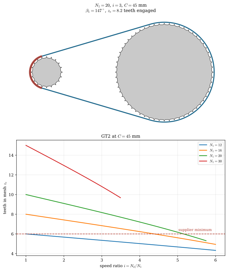
Example 2: The GT2 stage of the test rig
A stage like the one in Figure 9.10.1 drives an 80 tooth printed pulley from a 20 tooth bought one on a closed GT2 loop of 400 mm, which is 200 teeth. We want the pitch and outside diameters of both pulleys, the centre distance the belt fixes, the wrap angles and the teeth in mesh (Figure 9.10.11).
Code
from scipy.optimize import brentq

p_GT2, U_GT2 = 2.0, 0.254                 # mm, pitch and differential from tbl-belt-sections
N1r, N2r, Nb_r = 20, 80, 200              # bought pulley, printed pulley, 400 mm loop
d1r, d2r = N1r*p_GT2/np.pi, N2r*p_GT2/np.pi
do1r, do2r = d1r - 2*U_GT2, d2r - 2*U_GT2


def belt_length(C, d1, d2):
    # pitch length of an open drive, eq-belt-length
    a = np.arcsin((d2 - d1)/(2*C))
    return 2*C*np.cos(a) + d2/2*(np.pi + 2*a) + d1/2*(np.pi - 2*a)


# the stock belt fixes L; the centre distance lies between touching pulleys and half the belt
Cr = brentq(lambda C: belt_length(C, d1r, d2r) - Nb_r*p_GT2, (d1r + d2r)/2, Nb_r*p_GT2/2)
ar = np.arcsin((d2r - d1r)/(2*Cr))
b1r, b2r = np.pi - 2*ar, np.pi + 2*ar
ze1, ze2 = N1r*b1r/(2*np.pi), N2r*b2r/(2*np.pi)
Lsr = Cr*np.cos(ar)                       # free span, needed for the pluck frequency
Code
fig, ax = plt.subplots(figsize=(9, 4.2))
for cx, n, dp_ in ((0.0, N1r, d1r), (Cr, N2r, d2r)):
    t, rr = pulley_outline(n, dp_ - 2*U_GT2, 0.76)
    ax.fill(cx + rr*np.cos(t), rr*np.sin(t), color=GREY, lw=0)
    ax.plot(cx + rr*np.cos(t), rr*np.sin(t), 'k-', lw=0.5)
    ax.plot([cx], [0], 'k+', ms=7)
draw_belt(ax, d1r/2, d2r/2, Cr, lw=2.0)
th = np.linspace(np.pi/2 + ar, 3*np.pi/2 - ar, 200)
ax.plot(d1r/2*np.cos(th), d1r/2*np.sin(th), color=RED, lw=4.0, solid_capstyle='butt', zorder=5)
ax.annotate("", xy=(0, -d2r/2 - 9), xytext=(Cr, -d2r/2 - 9),
            arrowprops=dict(arrowstyle='<->', lw=1.0))
ax.text(Cr/2, -d2r/2 - 16, fr"$C = {Cr:.2f}$ mm", ha='center', fontsize=11)
ax.text(-d1r/2 - 4, 0, fr"$\beta_1 = {np.degrees(b1r):.1f}^\circ$" + "\n"
        + fr"$z_{{e1}} = {ze1:.2f}$", ha='right', va='center', fontsize=10.5, color=RED)
ax.text(Cr + d2r/2 + 4, 0, fr"$\beta_2 = {np.degrees(b2r):.1f}^\circ$" + "\n"
        + fr"$z_{{e2}} = {ze2:.1f}$", ha='left', va='center', fontsize=10.5)
ax.text(0, d2r/2 + 4, f"{N1r} teeth, bought", ha='center', fontsize=10)
ax.text(Cr, d2r/2 + 4, f"{N2r} teeth, printed", ha='center', fontsize=10)
ax.set_xlim(-48, Cr + d2r/2 + 48); ax.set_ylim(-d2r/2 - 21, d2r/2 + 10)
ax.set_aspect('equal'); ax.axis('off')
plt.tight_layout()
plt.show()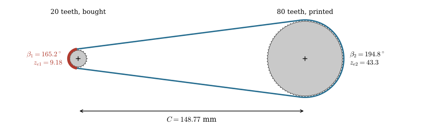
9.10.5 and 9.10.7 with \(U = 0.254\) mm give the diameters of the two pulleys,
\[ \begin{aligned}d_1 &=12.732\ \text{mm}, \qquad d_{o1} = d_1 - 2U =12.224\ \text{mm}\\ d_2 &=50.93\ \text{mm}, \qquad d_{o2} = d_2 - 2U =50.422\ \text{mm}\end{aligned} \]
The belt fixes \(L = 200 \cdot 2 = 400\) mm. Solving 9.10.9 for \(C\), then 9.10.8 and 9.10.10, gives the layout,
\[ \begin{aligned}C &=148.77\ \text{mm}, \qquad \alpha =7.38^\circ, \qquad L_s = C\cos\alpha =147.54\ \text{mm}\\ \beta_1 &=165.2^\circ, \qquad z_{e1} =9.18\\ \beta_2 &=194.8^\circ, \qquad z_{e2} =43.3\end{aligned} \]
Nine teeth in mesh on the small pulley clear the six that the ratings assume. The large pulley has more than four times as many teeth sharing the same belt pull, which is why it is the one we print.
Tensioning
A synchronous belt needs only enough tension to keep the teeth seated so that the belt cannot climb. Under-tensioning causes ratcheting; over-tensioning wears the bearings and fatigues the cords, and neither fault is visible.
Measuring tension by frequency
The free span between two pulleys is a string under tension, so its fundamental frequency is
\[ f = \frac{1}{2L_s}\sqrt{\frac{T}{\mu_L}} \tag{9.10.11}\]
with \(L_s = C\cos\alpha\) the free span length, \(T\) the static tension and \(\mu_L\) the belt mass per unit length. Inverting it,
\[ T = 4\,\mu_L L_s^2 f^2 \tag{9.10.12}\]
turns a tension specification into something measurable with a microphone. Pluck the span, hold a phone near it, and read the frequency from a tuner application.
Code
fig, ax = plt.subplots(figsize=(7.6, 4.4))
mu_L = 1.4e-3*6                                  # kg/m: 1.4 g/m per mm of width, 6 mm wide
Ls = np.linspace(0.05, 0.40, 300)
for T_ in (10, 20, 30, 40):
    ax.plot(Ls*1000, np.sqrt(T_/mu_L)/(2*Ls), lw=1.9, label=fr"$T={T_}$ N")
ax.set_xlabel(r"free span $L_s$  [mm]")
ax.set_ylabel(r"target pluck frequency $f$  [Hz]")
ax.set_yscale('log')
ax.grid(alpha=0.3, which='both')
ax.legend(fontsize=9, title=r"6 mm GT2, $\mu_L=8.4$ g/m")
ax.set_title(r"$f = \dfrac{1}{2L_s}\sqrt{T/\mu_L}$", fontsize=12)
plt.tight_layout()
plt.show()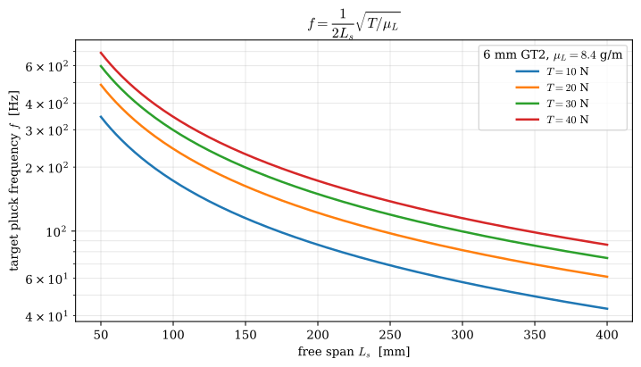
9.10.12 is also the reason to distrust the frequency targets that circulate in the printer community. Figures such as 40 to 60 Hz for a 200 to 250 mm span on a Cartesian machine, or 110 to 140 Hz for the longer spans of a CoreXY, are tension specifications in disguise. They transfer to another machine only if \(L_s\) and \(\mu_L\) both match. Weigh a known length of the belt to get \(\mu_L\), decide the tension, and compute the target for the span in front of you.
Taking up tension
A belt at roughly the right tension deflects two to three millimetres at midspan under firm finger pressure. It takes two seconds; it checks the tension but does not set it. Gates turns the same test into a specification: the force at midspan that deflects the span by \(1/64\) of its length has to lie between a minimum and a maximum computed from the design power [1].
Tension is taken up either by moving a pulley or by pressing on a span. Sliding the motor on slotted holes is the simplest arrangement and needs no extra parts. An eccentric idler gives fine adjustment in very little space. A spring loaded idler holds tension as the belt beds in and as the surrounding structure creeps. On a printed frame that creep is a real effect over the first hours of running, and it explains a drive that was tight on Monday and ratchets on Wednesday. Whichever mechanism is used, press on the slack side.
Example 3: Installation tension of the test rig stage
The 20 tooth pulley of Example 2 delivers \(M_1 = 0.25\) N·m at 600 rpm. We want the installation tension, the strand tensions in running, the load on the bearings and the frequency the plucked span should sound at, and we compare the bearing load with that of a flat belt on the same pulleys (Figure 9.10.13).
A service factor \(K_A\) multiplies the nominal load to cover the shocks and duty that the nominal value does not show. Gates tabulates it from \(1.0\) for instrumentation on an electric motor to \(2.5\) for a crusher on a single cylinder engine in continuous service; for measuring equipment on a DC motor in normal service, which a test rig is, it is \(1.2\) [1]. The installation rule of the same manual (its Formula 4), written with the design pull \(K_A T_e\), where \(T_e = T_1 - T_2\), and converted from pounds and feet per minute, reads
\[ T_{st} = 0.527\,K_A T_e + \mu_L v^2 \tag{9.10.13}\]
so each strand is installed at a little more than half the design pull, plus the centrifugal tension. In running, the tight side gains half the pull and the slack side loses it, \(T_{1,2} = T_{st} \pm T_e/2\), which leaves the slack side just taut.
Code
M1r, n1r, K_A = 0.25, 600, 1.2            # N m, rpm, Gates service factor
mu_GT2 = 1.4e-3*6                         # kg/m, Gates 2MGT constant times 6 mm width
Te = 2*M1r/(d1r/1000)                     # eq-belt-torque: the pull the torque needs
v_r = n1r*2*np.pi/60*d1r/2000             # belt speed, m/s
P_r = Te*v_r                              # eq-belt-power
Tst = 0.527*K_A*Te + mu_GT2*v_r**2        # eq-belt-tst
T1s, T2s = Tst + Te/2, Tst - Te/2
f_r = np.sqrt(Tst/mu_GT2)/(2*Lsr/1000)    # eq-belt-frequency on the free span

# flat belt, mu = 0.35, on the same small pulley: eq-belt-slip must hold at the design pull
Ted = K_A*Te
T1f = Ted/(1 - np.exp(-0.35*b1r))
T2f = T1f - Ted
9.10.1 and 9.10.2 give the pull, the belt speed and the power, and 9.10.13 with 9.10.11 the installation,
\[ \begin{aligned}T_e &= \frac{2M_1}{d_1} =39.3\ \text{N}, \qquad v =0.4\ \text{m/s}, \qquad P =15.7\ \text{W}\\ T_{st} &=24.8\ \text{N}, \qquad T_1 =44.5\ \text{N}, \qquad T_2 =5.2\ \text{N}\\ f &= \frac{1}{2L_s}\sqrt{\frac{T_{st}}{\mu_L}} =184.0\ \text{Hz}\end{aligned} \]
The centrifugal term is a thousandth of a newton at \(0.4\) m/s and plays no part. The plucked span should sound at about 185 Hz, close to the F sharp below middle C, and a tuner app reads it directly. The belt pushes the shafts apart with about \(T_1 + T_2 = 2T_{st}\), some 50 N.
A flat belt with \(\mu = 0.35\) on the same pulleys has to hold 9.10.3 at the design pull, which fixes its tight-side tension,
\[ \begin{aligned}T_1 &= \frac{K_A T_e}{1 - e^{-\mu\beta_1}} =74.1\ \text{N}, \qquad T_2 =27.0\ \text{N}\\ T_1 + T_2 &=101.0\ \text{N}\end{aligned} \]
twice the bearing load of the toothed belt, and with no margin left against slip.
Code
fig, ax = plt.subplots(figsize=(8, 3.6))
labels = [r"$T_1$", r"$T_2$", r"$T_1+T_2$"]
y = np.arange(3)
ax.barh(y - 0.18, [T1s, T2s, T1s + T2s], height=0.34, color=BLUE, label="GT2, Gates tension")
ax.barh(y + 0.18, [T1f, T2f, T1f + T2f], height=0.34, color=GREY,
        label=r"flat belt, $\mu=0.35$, at the slip limit")
for yy, a_, b_ in zip(y, [T1s, T2s, T1s + T2s], [T1f, T2f, T1f + T2f]):
    ax.text(a_ + 1, yy - 0.18, f"{a_:.0f} N", va='center', fontsize=9.5, color=BLUE)
    ax.text(b_ + 1, yy + 0.18, f"{b_:.0f} N", va='center', fontsize=9.5)
ax.set_yticks(y, labels, fontsize=12)
ax.invert_yaxis()
ax.set_xlabel("tension [N]")
ax.set_xlim(0, 120); ax.set_xticks([0, 20, 40, 60, 80, 100, 120])
ax.grid(axis='x', alpha=0.3)
ax.legend(fontsize=9, loc='upper center', bbox_to_anchor=(0.5, -0.22), ncol=2, frameon=False)
plt.tight_layout()
plt.show()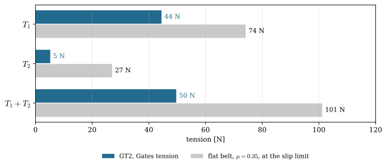
Printing a pulley
Small synchronous pulleys are the part most often printed in a light drivetrain, and they are also close to the limit of what the process can hold.

Our reference process is a \(0.4\) mm nozzle at \(0.2\) mm layer height, which holds roughly \(\pm 0.1\) mm of deviation per surface [5]; see the process and its tolerances. Set that figure against the two profiles of Trapezoidal and curvilinear teeth. It is a fixed absolute error, so what matters is the size of the feature it is applied to.
Code
def offset_polyline(x, y, d):
    # Offset a polyline by d along its local normal.
    x, y = np.asarray(x, float), np.asarray(y, float)
    dx, dy = np.gradient(x), np.gradient(y)
    L = np.hypot(dx, dy); L[L == 0] = 1e-12
    nx, ny = -dy/L, dx/L
    if np.mean(ny) < 0:
        nx, ny = -nx, -ny
    return x + d*nx, y + d*ny


def densify(x, y, step=0.004):
    x, y = np.asarray(x, float), np.asarray(y, float)
    sc = np.concatenate([[0], np.cumsum(np.hypot(np.diff(x), np.diff(y)))])
    tt = np.arange(0, sc[-1], step)
    return np.interp(tt, sc, x), np.interp(tt, sc, y)


fig, ax = plt.subplots(figsize=(10.5, 4.0))
dev = 0.1
for title, p, ht, kind, y0 in [("XL groove, $p=5.08$ mm", 5.08, 1.27, 'trap', 2.8),
                               ("GT2 groove, $p=2.00$ mm", 2.00, 0.76, 'curv', -1.8)]:
    n = int(16.0 // p)
    x0 = -n*p/2
    if kind == 'trap':
        xs, ys = [x0], [0.0]
        for k in range(n):
            tx, ty = trap_tooth(x0 + (k + 0.5)*p, p, ht, 25, 0.273)
            xs += tx
            ys += ty
        xs.append(x0 + n*p); ys.append(0.0)
        xs, ys = np.array(xs), np.array(ys)
    else:
        xs = np.linspace(x0, x0 + n*p, 1500)
        u = np.clip((np.abs((((xs - x0)/p) % 1.0) - 0.5) - 0.18)/0.32, 0, 1)
        ys = -ht*np.sqrt(np.clip(1 - u**2, 0, 1))
    dx_, dy_ = densify(xs, ys)
    ox1, oy1 = offset_polyline(dx_, dy_, dev)
    ox2, oy2 = offset_polyline(dx_, dy_, -dev)
    ax.fill(np.concatenate([ox1, ox2[::-1]]),
            np.concatenate([oy1, oy2[::-1]]) + y0, color=RED, alpha=0.40, lw=0)
    ax.plot(dx_, y0 + dy_, 'k-', lw=1.6)
    ax.annotate("", xy=(x0 - 0.6, y0), xytext=(x0 - 0.6, y0 - ht),
                arrowprops=dict(arrowstyle='<->', lw=1.1))
    ax.text(x0 - 0.9, y0 - ht/2, fr"$h_t={ht}$", ha='right', va='center', fontsize=9.5)
    ax.text(x0 + n*p + 0.8, y0 - ht/2,
            fr"$\pm0.1$ mm $=\pm{100*dev/ht:.0f}\%$ of $h_t$", va='center',
            fontsize=12, color=RED)
    ax.text(x0 - 0.9, y0 + 0.55, title, fontsize=11, ha='left')
ax.plot([-8, -3], [-3.6, -3.6], 'k-', lw=2)
ax.text(-5.5, -4.2, "5 mm", ha='center', fontsize=9)
ax.set_xlim(-12.5, 18.5); ax.set_ylim(-4.8, 4.4)
ax.set_aspect('equal'); ax.axis('off')
plt.tight_layout()
plt.show()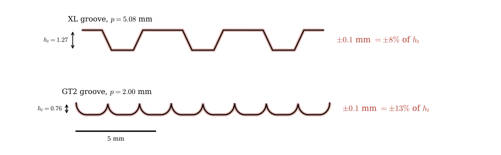
A printed GT2 pulley works at the resolution limit of the process; an XL pulley has margin. Where the choice is open and the drive is printed, the coarser pitch is the safer engineering decision. Where the pitch is fixed by the belt stock, buy the small pulley on the motor shaft, where torque per tooth is highest and the diameter smallest, and print only what cannot be bought, such as a pulley integrated into a wheel hub or a housing. The drive of Figure 9.10.16 is built that way.
The process adds four rules of its own (Table 9.10.2).
| Rule | Reason |
|---|---|
| Print with the pulley axis vertical | the teeth are built from stacked perimeters, and the tangential load acts in the plane of the layers, not across them, where the part is far weaker (orientation) |
| Chamfer the bottom of the tooth band | elephant foot fattens the first layers, and a fat first tooth binds the belt |
| Hexagonal or square bore, or crush ribs about 0.2 mm under in a bore about 0.4 mm over | a printed circular press fit is unreliable (fits in printed parts) |
| Heat-set insert for a grub screw undone more than once | a thread cut in plastic wears out on reassembly (fastening) |
NoteGetting the tooth form
A purchased pulley comes with a manufacturer’s STEP file, correct by definition, and the interface should be taken from it without redrawing. Failing that, a pulley generator builds the solid from tooth count, width, bore and flange settings, with the groove profile built in.1 Draw the groove yourself only when nothing else gives the geometry, and then from a dimensioned supplier drawing, since the 2 mm form is in no standard. The pitch circle comes from 9.10.5, the tip circle from 9.10.7, and one groove is laid on the centreline and patterned \(N\) times, as for the involute tooth in the gear model.
Example 4: Checking the printed pulley
The 80 tooth pulley of Example 2 is printed with the reference process. How large are its teeth against the nozzle, how far out of phase can the belt run over the wrap, and what happens to a 20 tooth pulley printed to the marketplace 13.73 mm (Figure 9.10.17)?
One pitch measured along the land is \(\pi d_o/N\): \(1.98\) mm on the 80 tooth pulley and \(1.92\) mm on the 20 tooth one, so a groove and a land share about five nozzle widths whatever the tooth count. A larger pulley does not get larger teeth. It gets more of them in mesh: 43 against 9 in Example 2, so each tooth of the printed pulley carries \(T_e/z_{e2} \approx 0.9\) N against \(4.3\) N on the bought one.
The diameter error matters through the phase. If the land comes out \(\Delta d\) larger than \(d_o\), the cord rides on a circle \(\Delta d\) larger than \(d_p\). The grooves are still \(2\pi/N\) apart, so the cord between two groove centres is \(p\,(1 + \Delta d/d_p)\) long while the belt brings one pitch \(p\). Over the \(z_e = N\beta/(2\pi)\) teeth in mesh the belt falls behind the grooves by
\[ e = z_e\,p\,\frac{\Delta d}{d_p} = \frac{\beta\,\Delta d}{2} \tag{9.10.14}\]
which is the extra arc that the larger circle gives over the wrap. It does not depend on the tooth count.
Code
dd_print = 0.2                            # mm on the diameter: +-0.1 mm on each side
dd_gates = 0.10                           # mm, Gates OD tolerance +0.004 in, 2 to 4 in sprockets
dd_list = 13.73 - do1r                    # mm, the listing against the correct land
e_print2 = b2r*dd_print/2                 # eq-belt-phase-error, printed 80 tooth pulley
e_gates = np.pi*dd_gates/2                # machined sprocket over half a turn
e_list1 = b1r*dd_list/2                   # 20 tooth pulley printed to the listing
For the printed land, a machined sprocket at Gates’ outside diameter tolerance of \(+0.10/-0\) mm [1], and the 20 tooth pulley drawn to the listing,
\[ \begin{aligned}e_\text{printed} &= \frac{\beta_2\,(0.2\ \text{mm})}{2} =0.34\ \text{mm}, \qquad e_\text{machined} \le \frac{\pi\,(0.10\ \text{mm})}{2} =0.16\ \text{mm}\\ e_\text{listing} &= \frac{\beta_1\,(13.73 - 12.22)\ \text{mm}}{2} =2.17\ \text{mm}\end{aligned} \]
Code
fig, ax = plt.subplots(figsize=(8, 4.6))
dd = np.linspace(-0.3, 1.7, 300)
ax.axvspan(-dd_print, dd_print, color=RED, alpha=0.15, lw=0)
ax.text(0, 2.35, "printed\n$\\pm0.2$ mm", ha='center', fontsize=9, color=RED)
ax.axvspan(0, dd_gates, color=BLUE, alpha=0.30, lw=0)
ax.text(dd_gates + 0.01, -0.35, "machined", fontsize=9, color=BLUE)
ax.plot(dd, b1r*dd/2, '-', color='k', lw=1.8, label=fr"20 teeth, $\beta_1={np.degrees(b1r):.0f}^\circ$")
ax.plot(dd, b2r*dd/2, '--', color='k', lw=1.8, label=fr"80 teeth, $\beta_2={np.degrees(b2r):.0f}^\circ$")
ax.axhline(p_GT2, color=RED, lw=1.2, ls=':')
ax.text(-0.28, p_GT2 + 0.06, "one pitch, $p = 2$ mm", fontsize=9, color=RED)
ax.plot([dd_list], [e_list1], 'o', color=RED, ms=7)
ax.annotate("listing, 13.73 mm", xy=(dd_list, e_list1), xytext=(0.75, 2.45),
            fontsize=9.5, arrowprops=dict(arrowstyle='->', lw=0.9))
ax.set_xlabel(r"error of the land diameter $\Delta d$ [mm]")
ax.set_ylabel(r"phase error over the wrap $e$ [mm]")
ax.set_xlim(-0.3, 1.7); ax.set_ylim(-0.5, 2.9)
ax.set_xticks([-0.3, 0, 0.2, 0.5, 1.0, 1.5, 1.7])
ax.set_yticks([-0.5, 0, 0.5, 1.0, 1.5, 2.0, 2.5, 2.9])
ax.grid(alpha=0.3); ax.legend(fontsize=9, loc='lower right')
plt.tight_layout()
plt.show()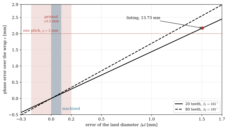
A printed land puts the belt up to a third of a millimetre, a sixth of a pitch, out of phase at the end of the wrap, about twice what a machined sprocket allows. The tooth flanks and the groove clearance have to absorb that, and it is the reason to measure the land with calipers before fitting the belt. The listing value is out by more than a whole pitch: the belt cannot seat at all.
What goes wrong
Most failures of a synchronous drive trace back to a quantity computed above (Table 9.10.3).
| Failure | Cause | Cure |
|---|---|---|
| Ratcheting | too few teeth in mesh (9.10.10) or too little tension (9.10.12) | longer centre distance, larger small pulley, more tension |
| Tooth shear | overload, shock, fewer than six teeth in mesh, a backside idler | wider belt, coarser pitch, inside idler |
| Cord fatigue, cracking | too small a pulley; back-bending over an outside idler | respect the minimum pulley size; use an inside idler |
| Flange climb, edge wear | pulley misalignment | align to within \(1/4^\circ\); tension does not help |
| Bearing wear | excess \(T_1+T_2\), which does no work (9.10.2) | lower the tension |
TipIn industry: the belt maker’s manual sizes the drive
Industrial belt drives are selected from the belt maker’s design manual or its software. The designer multiplies the motor power by a service factor read from a table of driving and driven machines, picks the pitch from a chart of design power against the speed of the faster shaft, and reads pulley pairs, stock belt lengths and centre distances from drive selection tables.
The width follows from tabulated power ratings, corrected by a belt length factor and by the teeth-in-mesh factor of Teeth in mesh. On electric motors the motor pulley may not be smaller than the NEMA minimum diameter for the motor’s power and speed, because a smaller pulley needs a larger pull for the same torque and overloads the motor bearings [1]. Gates does not recommend fixed centre distances for power drives, and the mounting gets a tabulated allowance for fitting the belt without forcing it over a flange and for tensioning it over its life.
Tension is then set by the deflection force at midspan, or measured with a sonic tension meter, which listens to the plucked span and evaluates 9.10.12 from the unit mass, width and span entered for the belt [4]. The 2 and 3 mm belts of printers and small machines have their own catalogue, Gates’ Light Power & Precision Drives manual, and the same steps apply.
Problems
Problem 1: A short GT2 loop. A 16 tooth GT2 pulley drives a 40 tooth one on a 300 mm closed loop, laid out as in Figure 9.10.9. Find the centre distance, the wrap angle on the small pulley and the teeth in mesh.
Answer: \(d_1 = 10.19\) mm, \(d_2 = 25.46\) mm; 150 teeth give \(C = 121.8\) mm, \(\beta_1 = 172.8^\circ\) and \(z_e = 7.7\), above the six that the ratings assume.
Problem 2: Too few teeth. A 12 tooth GT2 pinion drives a 60 tooth pulley at \(C = 40\) mm (Figure 9.10.10). How many teeth are in mesh, how does Gates derate the belt, and what would you change?
Answer: \(\sin\alpha = (38.20 - 7.64)/80\), so \(\alpha = 22.5^\circ\), \(\beta_1 = 135.1^\circ\) and \(z_e = 4.5\). Four teeth are in full contact, so the rating is multiplied by \(0.6\). Even \(180^\circ\) of wrap gives a 12 tooth pulley only six teeth, so the pinion has to grow: a 16 tooth pinion with an 80 tooth pulley reaches \(z_e = 6\) at \(C \ge 53\) mm.
Problem 3: A printer belt. A printer axis runs a 6 mm GT2 belt over a free span of 300 mm, and the belt should carry 25 N (Figure 9.10.12). What frequency should the plucked span give? What tension would you actually set if you tuned to that frequency with \(\mu_L = 2.1\) g/m in the calculation instead of the 8.4 g/m of the real belt?
Answer: \(f = \sqrt{25/0.0084}/(2 \cdot 0.3) = 91\) Hz. With the wrong mass the computed target is \(f = 182\) Hz, and tuning the real belt to it gives four times the intended tension, 100 N: tension scales with \(\mu_L\) at a given frequency.
Problem 4: A smaller listing. A listing gives a 16 tooth GT2 pulley an outside diameter 1.0 mm above its pitch diameter, as the 13.73 mm listing does for 20 teeth. Find the right outside diameter and the phase error over \(180^\circ\) of wrap for a pulley printed to the listing (Figure 9.10.17).
Answer: \(d_p = 10.19\) mm, \(d_o = 9.68\) mm. The listing is \(\Delta d = 1.51\) mm too large, and 9.10.14 gives \(e = \pi \cdot 1.51/2 = 2.4\) mm, more than a pitch. The error is the same for any tooth count, because \(e\) depends only on \(\beta\) and \(\Delta d\).
Problem 5: XL instead. Repeat the printing check of Figure 9.10.15 for a 20 tooth XL pulley: find \(d_p\) and \(d_o\), the printing envelope as a fraction of the tooth height, and one pitch along the land in 0.4 mm nozzle widths.
Answer: \(d_p = 20 \cdot 5.08/\pi = 32.34\) mm, \(d_o = 31.83\) mm with \(U = 0.254\) mm. \(0.1/1.27 = 8\,\%\) of \(h_t\), and \(\pi d_o/N = 5.0\) mm is \(12.5\) nozzle widths, against about five for GT2.
Problem 6: Which idler? In Figure 9.10.4, which of the idlers (b) and (c) increases the wrap on the small pulley? Which would you use on a toothed belt, and how?
Answer: The outside idler (b) pushes the span into the loop and increases the wrap; the inside idler (c) reduces it. On a toothed belt Gates prefers the inside idler on the slack side, grooved below 40 grooves, because a backside idler bends the belt backwards and causes cracking and tooth shear. If wrap is short, open the centre distance instead.
Further reading
Budynas and Nisbett [6, Ch. 17] treat flat, V and timing belts and roller chains together as flexible mechanical elements, with the flat belt’s friction analysis in full. ISO 5296 [2] and its pulley companion ISO 5294 [7] define the trapezoidal sections MXL to XXH, and ISO 13050 [3] the curvilinear systems from 3 mm pitch upwards. The Gates PowerGrip GT2 design manual [1] is the procedure behind the In industry callout: service factors, selection tables, the teeth-in-mesh correction, idlers, installation tension and a troubleshooting table. Gates’ Light Power & Precision Drives manual (catalogue 17183) covers the 2 and 3 mm belts. The manual of the Gates sonic tension meter [4] states the string formula of 9.10.12 and lists the unit mass of most belt sections. For printed pulleys, Rahix’s design rules [5] give the process figures used in Printing a pulley.
References
[1]
PowerGrip GT2 belt drive design manual. Denver, Colorado: The Gates Rubber Company; 2000.
[2]
ISO 5296:2012 Synchronous belt drives – Belts with pitch codes MXL, XXL, XL, L, H, XH and XXH – Metric and inch dimensions. Geneva, Switzerland: International Organization for Standardization; 2012.
[3]
ISO 13050:2022 Synchronous belt drives – Metric pitch, curvilinear profile systems G, H, R and S, belts and pulleys. Geneva, Switzerland: International Organization for Standardization; 2022.
[4]
550C gates sonic tension meter manual. Gates Corporation; 2021.
[5]
Rahix. Design for 3D-printing 2025. https://blog.rahix.de/design-for-3d-printing/.
[6]
Budynas RG, Nisbett JK. Shigley’s mechanical engineering design. 10th ed. New York: McGraw-Hill Education; 2014.
[7]
ISO 5294:2012 Synchronous belt drives – Pulleys. Geneva, Switzerland: International Organization for Standardization; 2012.