import numpy as np
import sympy as sp
import matplotlib.pyplot as plt
import matplotlib_inline
from mechanicskit import la, ltx, arrow
from mechanicskit import sketch as sk

# The plots in this chapter are line drawings, so they are kept as vectors
# and stay sharp at any zoom.
matplotlib_inline.backend_inline.set_matplotlib_formats('svg')
plt.style.use('default')                      # white background
plt.rcParams.update({'mathtext.fontset': 'cm', 'font.family': 'serif'})   # reset by the style

F_1, F_2, F_3 = 600, 500, 8004.2 Force Vector Examples
“Solving problems is a practical skill like, let us say, swimming. We acquire any practical skill by imitation and practice.”
— George Pólya, How to Solve It, 1945
Every example below follows the same four steps. We start from the figure, write the solution as a mathematical model by hand, carry the model out in code, and verify the result with a drawing. The code only executes equations that already stand on the page.
Example 1 – Resultant of three forces
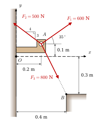
Define the force vectors \(\bm F_1\), \(\bm F_2\), and \(\bm F_3\) of Figure 4.2.1, then calculate and plot the resultant \(\bm R\).
Each force is its magnitude times a unit vector along its line of action, \(\bm F_i = F_i \bm e_i\), so the work lies in reading the three directions off the figure. They are given in three different ways: an angle for \(\bm F_1\), a slope for \(\bm F_2\), and two points for \(\bm F_3\).
For \(\bm F_1\) the figure gives the angle \(35^\circ\) from the \(x\)-axis directly, so
\[ \bm e_1 = \begin{bmatrix} \cos 35^\circ \\ \sin 35^\circ \\ 0 \end{bmatrix}, \qquad \bm F_1 = F_1 \bm e_1 \]
ee_1 = sp.Matrix([sp.cos(sp.rad(35)), sp.sin(sp.rad(35)), 0])
FF_1 = F_1 * ee_1
For \(\bm F_2\) we avoid introducing an angle. The slope triangle gives a vector \(\bm v\) along the line of action, and normalizing it gives the direction,
\[ \bm e_2 = \frac{\bm v}{\|\bm v\|}, \quad \bm v = \begin{bmatrix} -4 \\ 3 \\ 0 \end{bmatrix}, \qquad \bm F_2 = F_2 \bm e_2 \]
ee_2 = sp.Matrix([-4, 3, 0]).normalized()
FF_2 = F_2 * ee_2
For \(\bm F_3\) the line of action runs from \(A\) to \(B\), and the figure gives both points relative to \(O\). The direction is the difference of the two position vectors, normalized,
\[ \bm e_3 = \frac{\bm r_{OB} - \bm r_{OA}}{\|\bm r_{OB} - \bm r_{OA}\|}, \quad \bm r_{OA} = \begin{bmatrix} 0.2 \\ 0.1 \\ 0 \end{bmatrix}, \quad \bm r_{OB} = \begin{bmatrix} 0.4 \\ -0.3 \\ 0 \end{bmatrix}, \qquad \bm F_3 = F_3 \bm e_3 \]
rr_OA = sp.Matrix([0.2, 0.1, 0])
rr_OB = sp.Matrix([0.4, -0.3, 0])
rr_AB = rr_OB - rr_OA

ee_3 = rr_AB.normalized()
FF_3 = F_3 * ee_3
The resultant is the sum of the three vectors, and its magnitude is the length of that sum,
\[ \bm R = \sum_{i=1}^{3} \bm F_i = F_1 \bm e_1 + F_2 \bm e_2 + F_3 \bm e_3, \qquad R = \|\bm R\| = \sqrt{R_x^2 + R_y^2} \]
RR = FF_1 + FF_2 + FF_3

ltx(r"\bm R = ", RR.evalf(4), r"\text{ N},\quad R = ", RR.norm().evalf(4), r"\text{ N}")
\[ \bm R = \left[\begin{matrix}449.3\\-71.4\\0\end{matrix}\right]\text{ N},\quad R = 454.9\text{ N} \]
A drawing is the quickest check of a vector sum. Vectors add tip to tail: if we move \(\bm F_2\) so that it starts where \(\bm F_1\) ends, and \(\bm F_3\) so that it starts where \(\bm F_2\) ends, the chain must end at the tip of \(\bm R\). In symbols, the tail of force \(k\) sits at the partial sum of the forces before it,
\[ \bm s_0 = \bm 0, \qquad \bm s_k = \bm s_{k-1} + \bm F_k = \sum_{i=1}^{k} \bm F_i, \qquad \bm s_n = \bm R \]
so force \(k\) is drawn from \(\bm s_{k-1}\) to \(\bm s_k\), and the last point of the chain is compared with the computed \(\bm R\). The function below draws both views, the forces from their common point and the same forces stacked, and we use it in the examples that follow.
Code
def to2(v):
    "The x and y components of a SymPy vector as floats."
    return np.array(v.tolist(), dtype=float).flatten()[:2]


def label_beside(ax, p0, p1, text, centre, off, color, at=0.5):
    "Label the arrow from p0 to p1, a fraction `at` along it, on the side facing away from centre."
    p0, p1 = np.asarray(p0, float), np.asarray(p1, float)
    mid, n = p0 + at*(p1 - p0), sk.normal(p1 - p0)
    side = 1 if np.dot(mid - centre, n) >= 0 else -1
    sk.label(ax, mid + side*off*n, text, color=color)


def force_polygon(forces, labels, resultant, unit='N', extra=(), at=None):
    "Left: the forces from one point. Right: the same forces tip to tail."
    F, R = [to2(f) for f in forces], to2(resultant)
    chain = np.cumsum([np.zeros(2)] + F, axis=0)
    fan = np.array([np.zeros(2), *F, R, *[to2(p) for p in extra]])
    R_label = r'$\boldsymbol{R}$'

    fig, axs = plt.subplots(1, 2, figsize=(9, 4.4))
    for ax, pts, title in ((axs[0], fan, 'From one point'), (axs[1], chain, 'Tip to tail')):
        lo, hi = pts.min(axis=0), pts.max(axis=0)
        pad = 0.2*(hi - lo).max()
        centre = pts.mean(axis=0)
        if ax is axs[0]:
            for f, lab in zip(F, labels):
                arrow([0, 0], f, color=sk.LOAD, ax=ax)
                sk.label(ax, f + 0.45*pad*sk.unit(f), lab, color=sk.LOAD)
            sk.label(ax, R + 0.45*pad*sk.unit(R), R_label, color=sk.GREEN)
        else:
            for tail, f, lab, t in zip(chain[:-1], F, labels, at or [0.5]*len(F)):
                arrow(tail, f, color=sk.LOAD, ax=ax)
                label_beside(ax, tail, tail + f, lab, centre, 0.35*pad, sk.LOAD, at=t)
            label_beside(ax, [0, 0], R, R_label, centre, 0.35*pad, sk.GREEN)
            ax.plot(*chain[-1], 'o', ms=11, mfc='none', mec='black', zorder=7)
        arrow([0, 0], R, color=sk.GREEN, ax=ax, zorder=4)
        ax.plot(0, 0, 'o', ms=5, color='black', zorder=6)
        ax.set(xlim=(lo[0] - pad, hi[0] + pad), ylim=(lo[1] - pad, hi[1] + pad),
               xlabel=f'$F_x$ [{unit}]', ylabel=f'$F_y$ [{unit}]', title=title)
        ax.set_aspect('equal')
        ax.grid(True, lw=0.4, alpha=0.5)
    fig.tight_layout()
    return fig, axs
Code
force_polygon([FF_1, FF_2, FF_3],
              [r'$\boldsymbol{F}_1$', r'$\boldsymbol{F}_2$', r'$\boldsymbol{F}_3$'], RR,
              at=(0.25, 0.5, 0.8));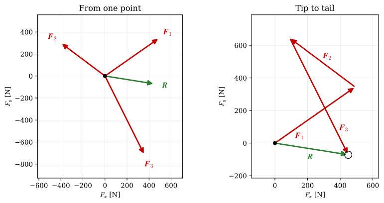
Figure 4.2.3 builds the right-hand view of Figure 4.2.2 one step at a time: the three forces grow out of \(A\), \(\bm F_2\) moves to the tip of \(\bm F_1\) and \(\bm F_3\) to the tip of \(\bm F_2\), and the resultant closes the chain.
In Figure 4.2.2 the chain ends on the tip of the computed resultant, so the sum is right. A wrong sign, or a sine swapped for a cosine, would leave a visible gap between the circle and the green arrow. The direction also agrees with Figure 4.2.1: the upward pulls of \(\bm F_1\) and \(\bm F_2\) nearly cancel the downward pull of \(\bm F_3\), and \(\bm F_1\) and \(\bm F_3\) both point to the right, so \(\bm R\) points to the right and slightly down.
Example 2 – Unknown spring force
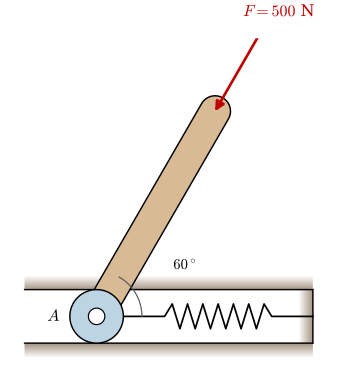
The force \(F = 500\) N in Figure 4.2.4 acts along the rod towards \(A\), so it points \(60^\circ\) below the negative \(x\)-axis. The spring acts on the wheel along the slot with a force \(\bm F_s\) of unknown magnitude. The slot walls can only push on the wheel at right angles to the slot, so they can balance a vertical force and nothing else. The wheel therefore stays in place only if the resultant of \(\bm F\) and \(\bm F_s\) is vertical,
\[ \bm F + \bm F_s = \bm R, \qquad \bm F_s = F_s \begin{bmatrix} 1 \\ 0 \\ 0 \end{bmatrix}, \quad \bm R = R \begin{bmatrix} 0 \\ -1 \\ 0 \end{bmatrix} \]
The applied force is known in full,
\[ \bm F = 500 \begin{bmatrix} -\cos 60^\circ \\ -\sin 60^\circ \\ 0 \end{bmatrix} \]
so the \(x\) and \(y\) components of the vector equation give two scalar equations for the two unknowns \(F_s\) and \(R\),
\[ \begin{aligned} x&: & -500\cos 60^\circ + F_s &= 0 \\ y&: & -500\sin 60^\circ &= -R \end{aligned} \]
F_s, R = sp.symbols('F_s R', real=True)

FF   = 500 * sp.Matrix([-sp.cos(sp.rad(60)), -sp.sin(sp.rad(60)), 0])
FF_s = F_s * sp.Matrix([1, 0, 0])
RR   = R * sp.Matrix([0, -1, 0])

sp.Eq(FF + FF_s - RR, sp.zeros(3,1)) | la
\[ {\def\arraystretch{1.0}\left[\begin{matrix}F_{s} - 250\\R - 250 \sqrt{3}\\0\end{matrix}\right] = \left[\begin{matrix}0\\0\\0\end{matrix}\right]} \]
sol = sp.solve(FF + FF_s - RR, [R, F_s])
sol | la
\[ \begin{aligned} F_{s} &= 250 \\[9.0pt] R &= 250 \sqrt{3} \end{aligned} \]
The spring carries the horizontal component of \(\bm F\), \(F_s = 500\cos 60^\circ = 250\) N, and the slot carries the vertical one, \(R = 500\sin 60^\circ = 250\sqrt{3} \approx 433\) N. The drawing verifies the vector equation \(\bm F + \bm F_s = \bm R\) itself: in Figure 4.2.5 the chain of \(\bm F\) followed by \(\bm F_s\) ends straight below the starting point, on the tip of the vertical \(\bm R\).
Code
force_polygon([FF, FF_s.subs(sol)], [r'$\boldsymbol{F}$', r'$\boldsymbol{F}_s$'],
              RR.subs(sol));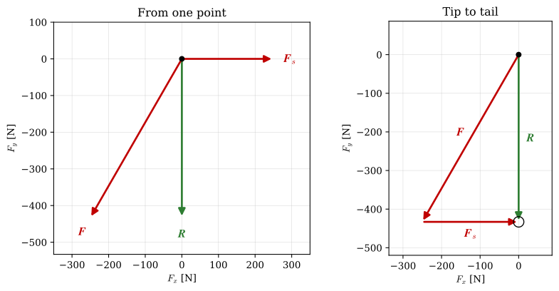
Example 3 – Rotated coordinate system
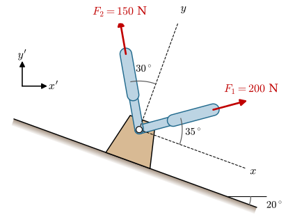
The angles in Figure 4.2.6 are measured from the axes of the inclined \(xy\)-base, so the two forces are easiest to write in that base,
\[ \bm F_1 = 200 \begin{bmatrix} \cos 35^\circ \\ \sin 35^\circ \\ 0 \end{bmatrix}_{xy}, \qquad \bm F_2 = 150 \begin{bmatrix} -\sin 30^\circ \\ \cos 30^\circ \\ 0 \end{bmatrix}_{xy} \]
We add them there,
\[ \bm R_{xy} = \bm F_1 + \bm F_2 = \begin{bmatrix} 200\cos 35^\circ - 150\sin 30^\circ \\ 200\sin 35^\circ + 150\cos 30^\circ \\ 0 \end{bmatrix}_{xy} \]
and then express the resultant in the \(x'y'\)-base.
FF_1_xy = 200 * sp.Matrix([ sp.cos(sp.rad(35)), sp.sin(sp.rad(35)), 0])
FF_2_xy = 150 * sp.Matrix([-sp.sin(sp.rad(30)), sp.cos(sp.rad(30)), 0])

RR_xy = FF_1_xy + FF_2_xy
To change base we need the base vectors of the \(xy\)-base written in \(x'y'\) components. The incline drops \(20^\circ\), so
\[ \bm e_x = \begin{bmatrix} \cos 20^\circ \\ -\sin 20^\circ \\ 0 \end{bmatrix}, \quad \bm e_y = \begin{bmatrix} \sin 20^\circ \\ \cos 20^\circ \\ 0 \end{bmatrix}, \quad \bm e_z = \begin{bmatrix} 0 \\ 0 \\ 1 \end{bmatrix} \]
These columns have a form that recurs throughout mechanics. The \(xy\)-base is the \(x'y'\)-base turned about the \(z\)-axis, here clockwise by \(20^\circ\). A base turned anticlockwise by an angle \(\varphi\) has \(\bm e_x = [\cos\varphi,\ \sin\varphi,\ 0]^\mathsf{T}\) and \(\bm e_y = [-\sin\varphi,\ \cos\varphi,\ 0]^\mathsf{T}\), and the base vectors above are these with \(\varphi = -20^\circ\).
The resultant is \(\bm R = R_x \bm e_x + R_y \bm e_y + R_z \bm e_z\) with the components \(R_x\), \(R_y\), \(R_z\) found above. Placing the base vectors as the columns of a matrix \(\bm A = [\bm e_x \;\; \bm e_y \;\; \bm e_z]\) turns this sum into a matrix product,
\[ \bm R_{x'y'} = \bm A \bm R_{xy} \]
and with the columns written out, \(\bm A\) is the rotation matrix about the \(z\)-axis,
\[ \boxed{\bm A(\varphi) = \begin{bmatrix} \cos\varphi & -\sin\varphi & 0 \\ \sin\varphi & \cos\varphi & 0 \\ 0 & 0 & 1 \end{bmatrix}} \tag{4.2.1}\]
Most texts write the rotation matrix \(\bm R\). In this chapter \(\bm R\) is the resultant force, so we call it \(\bm A\). For the incline, \(\bm A(-20^\circ)\) carries components in the inclined base over to the horizontal one.
theta = sp.rad(20)

ee_x = sp.Matrix([sp.cos(theta), -sp.sin(theta), 0])
ee_y = sp.Matrix([sp.sin(theta),  sp.cos(theta), 0])
ee_z = sp.Matrix([0, 0, 1])

A = sp.Matrix.hstack(ee_x, ee_y, ee_z)
RR = A @ RR_xy

ltx(r"\bm R_{xy} = ", RR_xy.evalf(4), r"\text{ N},\quad \bm R_{x'y'} = ", RR.evalf(4), r"\text{ N}")
\[ \bm R_{xy} = \left[\begin{matrix}88.83\\244.6\\0\end{matrix}\right]\text{ N},\quad \bm R_{x'y'} = \left[\begin{matrix}167.1\\199.5\\0\end{matrix}\right]\text{ N} \]
The way back, from the \(x'y'\)-base to the \(xy\)-base, is \(\bm R_{xy} = \bm A^{-1} \bm R_{x'y'}\). A square matrix is a rotation matrix when two conditions hold. Its columns are orthonormal, so that it is orthogonal,
\[ \bm A^\mathsf{T} \bm A = \bm I, \]
and its determinant is \(+1\),
\[ \det \bm A = \cos^2\varphi + \sin^2\varphi = 1. \]
The first condition keeps lengths and angles, and the second rules out a reflection, which is orthogonal too but has \(\det = -1\) and turns a right-handed base into a left-handed one. 4.2.1 meets both for every \(\varphi\): each column has length \(\sqrt{\cos^2\varphi + \sin^2\varphi} = 1\), the first two columns give \(-\cos\varphi\sin\varphi + \sin\varphi\cos\varphi = 0\), and the third is \(\bm e_z\).
Orthogonality also gives the way back for free: \(\bm A^{-1} = \bm A^\mathsf{T}\), so \(\bm R_{xy} = \bm A^\mathsf{T} \bm R_{x'y'}\). Turning back by \(-\varphi\) gives the same, since \(\bm A(-\varphi) = \bm A(\varphi)^\mathsf{T}\).
WarningNever invert a matrix computationally
Writing \(\bm A^{-1} \bm b\) is fine on paper but computing it with A**-1 @ b or np.linalg.inv(A) @ b is both slow and numerically unstable. Always solve the system \(\bm A \bm x = \bm b\) instead, using np.linalg.solve(A, b) or in this case simply A.T @ b since \(\bm A\) is orthogonal. This distinction becomes critical in larger systems (FEM, optimization) where explicit inversion can produce garbage results.
A change of base turns the components and leaves the vector itself alone, so its length must be the same in both bases. This follows from the orthogonality of \(\bm A\),
\[ \bm A^{\mathsf{T}} \bm A = \bm I \quad\Rightarrow\quad \|\bm R_{x'y'}\|^2 = (\bm A \bm R_{xy})^{\mathsf{T}} (\bm A \bm R_{xy}) = \bm R_{xy}^{\mathsf{T}} \bm A^{\mathsf{T}} \bm A \bm R_{xy} = \|\bm R_{xy}\|^2 \]
We check the orthogonality, the determinant and the two lengths.
ltx(r"\bm A^{\mathsf{T}} \bm A = ", sp.simplify(A.T @ A),
    r",\quad \det \bm A = ", sp.simplify(A.det()),
    r",\quad \|\bm R_{xy}\| = ", RR_xy.norm().evalf(6),
    r"\text{ N},\quad \|\bm R_{x'y'}\| = ", RR.norm().evalf(6), r"\text{ N}")
\[ \bm A^{\mathsf{T}} \bm A = \left[\begin{matrix}1 & 0 & 0\\0 & 1 & 0\\0 & 0 & 1\end{matrix}\right],\quad \det \bm A = 1,\quad \|\bm R_{xy}\| = 260.249\text{ N},\quad \|\bm R_{x'y'}\| = 260.249\text{ N} \]
The two lengths agree, and they must. The resultant is the pull the two struts exert on the bracket together, and that pull exists before anyone draws axes. A coordinate system is bookkeeping that we lay over the problem: turning it changes the three numbers we use to describe the force, and it leaves the force itself untouched. Its magnitude, \(260.2\) N, is therefore an invariant, a quantity that comes out the same in every base.
The same holds for everything else with a physical meaning. The angle between two forces follows from their dot product, and a rotation keeps dot products,
\[ (\bm A \bm a)^\mathsf{T} (\bm A \bm b) = \bm a^\mathsf{T} \bm A^\mathsf{T} \bm A \bm b = \bm a^\mathsf{T} \bm b, \]
so the angle between \(\bm F_1\) and \(\bm F_2\), and the work a force does along a displacement, are invariants too. A single component is not. \(R_x\) in the inclined base is the part of the force along the incline, the part that would make the bracket slide, while \(R_{x'}\) is its horizontal part. Both describe the same force; each answers a different question. This is the freedom a change of base buys us: we write each force in the base where its data are simplest, add there, and turn the result into the base where the question is asked, knowing that nothing physical has changed on the way. The idea returns with the stress tensor in Stress and strain states, where the principal stresses are the invariants that every choice of axes must agree on.
To draw the forces in the \(x'y'\)-base, each one is transformed in the same way as the resultant, \([\bm F_i]_{x'y'} = \bm A\, [\bm F_i]_{xy}\). Figure 4.2.7 shows them with the axes of the \(xy\)-base dashed. Seen from the dashed axes, \(\bm F_1\) lies \(35^\circ\) above \(x\) and \(\bm F_2\) lies \(30^\circ\) to the left of \(y\), as in Figure 4.2.6.
Code
fig, axs = force_polygon([A @ FF_1_xy, A @ FF_2_xy],
                         [r'$\boldsymbol{F}_1$', r'$\boldsymbol{F}_2$'], RR,
                         extra=[170*ee_x, 170*ee_y])
for e, name in ((ee_x, '$x$'), (ee_y, '$y$')):
    sk.guide(axs[0], [0, 0], 150*to2(e))
    sk.label(axs[0], 165*to2(e), name)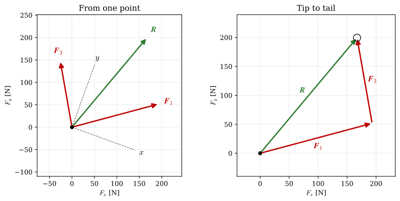
Example 4 – Two equal tooth forces
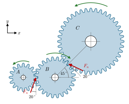
Gear \(B\) in Figure 4.2.8 receives a tooth force of magnitude \(F_n = 5500\) N at each of its two meshes. We want the resultant of the two forces, the load that the bearing of \(B\) must balance.
A tooth force is tilted by the pressure angle \(20^\circ\) from the common tangent of the two pitch circles. At the mesh with \(A\) the centres lie on a horizontal line, so the tangent is vertical and the force points \(90^\circ - 20^\circ = 70^\circ\) from the \(x\)-axis. At the mesh with \(C\) the line of centres rises at \(45^\circ\), the tangent lies at \(135^\circ\), and the force points \(135^\circ + 20^\circ = 155^\circ\) from the \(x\)-axis. The two directions and the resultant are therefore
\[ \bm e_1 = \begin{bmatrix} \cos 70^\circ \\ \sin 70^\circ \\ 0 \end{bmatrix}, \quad \bm e_2 = \begin{bmatrix} \cos 155^\circ \\ \sin 155^\circ \\ 0 \end{bmatrix}, \qquad \bm R = F_n \bm e_1 + F_n \bm e_2 = F_n (\bm e_1 + \bm e_2) \]
F_n = 5500

ee_1 = sp.Matrix([sp.cos(sp.rad(90 - 20)), sp.sin(sp.rad(90 - 20)), 0])
FF_1 = F_n * ee_1

ee_2 = sp.Matrix([sp.cos(sp.rad(135 + 20)), sp.sin(sp.rad(135 + 20)), 0])
FF_2 = F_n * ee_2

RR = FF_1 + FF_2
ltx(r"\bm R = ", RR.evalf(4), r"\text{ N},\quad R = ", RR.norm().evalf(4), r"\text{ N}")
\[ \bm R = \left[\begin{matrix}-3104.0\\7493.0\\0\end{matrix}\right]\text{ N},\quad R = 8110.0\text{ N} \]
The two forces are equal in magnitude, so they span a rhombus and the resultant must lie along its diagonal, halfway between them at \((70^\circ + 155^\circ)/2 = 112.5^\circ\). The half angle between the forces is \((155^\circ - 70^\circ)/2 = 42.5^\circ\), and each force contributes its projection onto the diagonal, so we expect
\[ \theta_R = \operatorname{atan2}(R_y, R_x) = 112.5^\circ, \qquad R = 2F_n\cos 42.5^\circ \]
Both agree with the computed vector.
ltx(r"\theta_R = ", sp.deg(sp.atan2(RR[1], RR[0])).evalf(4), r"^\circ,\quad 2F_n\cos 42.5^\circ = ",
    (2*F_n*sp.cos(sp.rad(42.5))).evalf(4), r"\text{ N}")
\[ \theta_R = 112.5^\circ,\quad 2F_n\cos 42.5^\circ = 8110.0\text{ N} \]
Code
force_polygon([FF_1, FF_2], [r'$\boldsymbol{F}_1$', r'$\boldsymbol{F}_2$'], RR);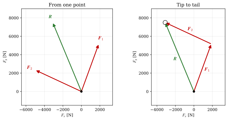
Example 5 – Force decomposition along two arms
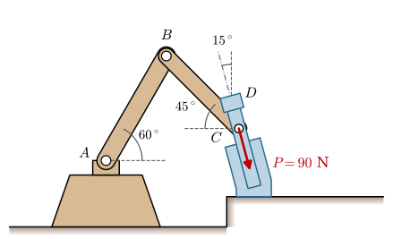
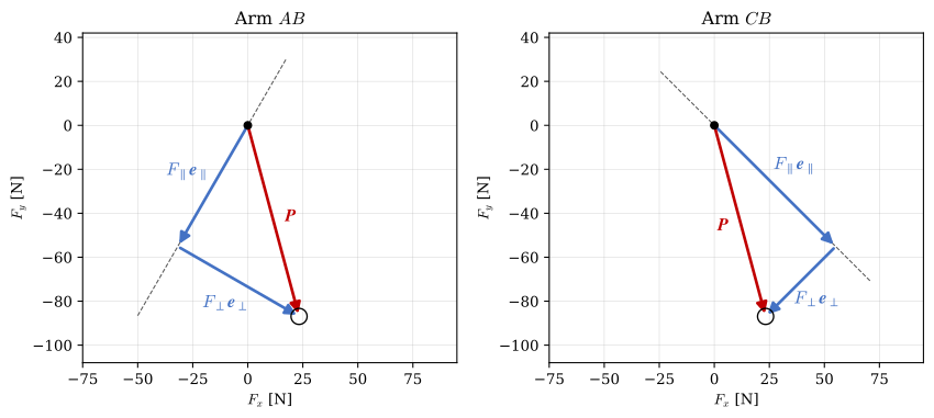
The force \(P = 90\) N in Figure 4.2.10 acts on the tool at \(C\) along the tool axis, which leans \(15^\circ\) from the vertical. We want its components parallel and perpendicular to each of the two arms. Arm \(AB\) rises at \(60^\circ\) from the horizontal, and arm \(CB\) rises at \(45^\circ\) from the horizontal, to the left from \(C\) up to \(B\). The force points down along the tool,
\[ \bm P = 90 \begin{bmatrix} \sin 15^\circ \\ -\cos 15^\circ \\ 0 \end{bmatrix} \]
For each arm we define one unit vector along it, pointing towards \(B\), and one perpendicular to it,
\[ \bm e_{AB\parallel} = \begin{bmatrix} \cos 60^\circ \\ \sin 60^\circ \\ 0 \end{bmatrix}, \quad \bm e_{AB\perp} = \begin{bmatrix} -\sin 60^\circ \\ \cos 60^\circ \\ 0 \end{bmatrix}, \qquad \bm e_{CB\parallel} = \begin{bmatrix} -\cos 45^\circ \\ \sin 45^\circ \\ 0 \end{bmatrix}, \quad \bm e_{CB\perp} = \begin{bmatrix} \sin 45^\circ \\ \cos 45^\circ \\ 0 \end{bmatrix} \]
PP = 90 * sp.Matrix([sp.sin(sp.rad(15)), -sp.cos(sp.rad(15)), 0])

# AB-arm basis, from A towards B
ee_ABpar  = sp.Matrix([ sp.cos(sp.rad(60)),  sp.sin(sp.rad(60)), 0])
ee_ABperp = sp.Matrix([-sp.sin(sp.rad(60)),  sp.cos(sp.rad(60)), 0])

# CB-arm basis, from C towards B
ee_CBpar  = sp.Matrix([-sp.cos(sp.rad(45)),  sp.sin(sp.rad(45)), 0])
ee_CBperp = sp.Matrix([ sp.sin(sp.rad(45)),  sp.cos(sp.rad(45)), 0])
Since all direction vectors have unit length, the dot product gives the scalar component directly. For each arm,
\[ F_{\parallel} = \bm P \cdot \bm e_{\parallel}, \qquad F_{\perp} = \bm P \cdot \bm e_{\perp} \]
For arm \(AB\) the first of these is \(F_{AB\parallel} = 90(\sin 15^\circ \cos 60^\circ - \cos 15^\circ \sin 60^\circ) = 90 \sin(15^\circ - 60^\circ) = -63.64\) N, and the other three follow in the same way.
F_ABpar  = sp.simplify(PP.dot(ee_ABpar))
F_ABperp = sp.simplify(PP.dot(ee_ABperp))
F_CBpar  = sp.simplify(PP.dot(ee_CBpar))
F_CBperp = sp.simplify(PP.dot(ee_CBperp))

ltx(r"F_{AB\parallel} &= ", F_ABpar.evalf(4), r"\text{ N}, & F_{AB\perp} &= ", F_ABperp.evalf(4),
    r"\text{ N} \\ F_{CB\parallel} &= ", F_CBpar.evalf(4), r"\text{ N}, & F_{CB\perp} &= ",
    F_CBperp.evalf(4), r"\text{ N}", aligned=True)
\[ \begin{aligned}F_{AB\parallel} &= -63.64\text{ N}, & F_{AB\perp} &= -63.64\text{ N} \\ F_{CB\parallel} &= -77.94\text{ N}, & F_{CB\perp} &= -45.0\text{ N}\end{aligned} \]
Both parallel components are negative: \(\bm P\) points against both unit vectors, down along each arm. The two unit vectors of an arm are perpendicular, so the components rebuild the force and, by Pythagoras, their squares add up to \(P^2\),
\[ \bm P = F_{\parallel} \bm e_{\parallel} + F_{\perp} \bm e_{\perp}, \qquad F_{\parallel}^2 + F_{\perp}^2 = P^2 = 90^2 = 8100\ \text{N}^2 \]
We check the second relation first, for both arms.
ltx(r"F_{AB\parallel}^2 + F_{AB\perp}^2 = ", sp.simplify(F_ABpar**2 + F_ABperp**2),
    r",\quad F_{CB\parallel}^2 + F_{CB\perp}^2 = ", sp.simplify(F_CBpar**2 + F_CBperp**2))
\[ F_{AB\parallel}^2 + F_{AB\perp}^2 = 8100,\quad F_{CB\parallel}^2 + F_{CB\perp}^2 = 8100 \]
The first relation is a vector sum, so it can be checked by drawing. Placed tip to tail, \(F_{\parallel} \bm e_{\parallel}\) followed by \(F_{\perp} \bm e_{\perp}\) must end at the tip of \(\bm P\), and Figure 4.2.11 shows that they do for both arms.
Code
fig, axs = plt.subplots(1, 2, figsize=(9, 4.4))
cases = (('AB', ee_ABpar, ee_ABperp, F_ABpar, F_ABperp),
         ('CB', ee_CBpar, ee_CBperp, F_CBpar, F_CBperp))
for ax, (name, e_par, e_perp, F_par, F_perp) in zip(axs, cases):
    par, perp = float(F_par)*to2(e_par), float(F_perp)*to2(e_perp)
    sk.guide(ax, -100*to2(e_par), 35*to2(e_par))               # the line of the arm
    arrow([0, 0], par, color=sk.BLUE, ax=ax)
    arrow(par, perp, color=sk.BLUE, ax=ax)
    arrow([0, 0], PP, color=sk.LOAD, ax=ax, zorder=6)
    centre = (par + to2(PP))/3
    label_beside(ax, [0, 0], par, r'$F_\parallel \boldsymbol{e}_\parallel$', centre, 13, sk.BLUE)
    label_beside(ax, par, par + perp, r'$F_\perp \boldsymbol{e}_\perp$', centre, 11, sk.BLUE)
    label_beside(ax, [0, 0], to2(PP), r'$\boldsymbol{P}$', centre, 8, sk.LOAD)
    ax.plot(0, 0, 'o', ms=5, color='black', zorder=7)
    ax.plot(*to2(PP), 'o', ms=11, mfc='none', mec='black', zorder=7)
    ax.set(xlim=(-75, 95), ylim=(-108, 42), xlabel='$F_x$ [N]', ylabel='$F_y$ [N]',
           title=f'Arm ${name}$')
    ax.set_aspect('equal')
    ax.grid(True, lw=0.4, alpha=0.5)
fig.tight_layout()