Code
m, L, R, x, s = sp.symbols('m L R x s', positive=True)
I_bar = sp.integrate(x**2*m/L, (x, -L/2, L/2))
I_disc = sp.integrate(s**2*2*m/R**2*s, (s, 0, R))“Momentum inertiae corporis respectu cuiuspiam axis est summa omnium productorum, quae oriuntur, si singula corporis elementa per quadrata distantiarum suarum ab axe multiplicentur.”
“The moment of inertia of a body with respect to some axis is the sum of all the products which arise, if the individual elements of the body are multiplied by the square of their distances from the axis.”
— Leonhard Euler, Theoria motus corporum solidorum seu rigidorum, 1765, §422, translated by Ian Bruce
A particle has a position and nothing else. A rigid body also has an orientation, and forces that do not pass through its centre of mass turn it. Particle kinetics needed one vector equation, Newton’s second law; a rigid body in plane motion needs a second, scalar one for the rotation. This chapter derives both from the particles that make up the body, introduces the mass moment of inertia that the rotation equation needs, and extends the energy balance of Work, energy and power with the kinetic energy of rotation. Two examples follow: a bar swinging as a pendulum, and a pendulum hinged on a cart that slides on a spring, where the two motions trade energy back and forth. A third finds the principal axes of a tilted bar from its inertia matrix.
Think of the body as a large number of particles \(m_i\) at the positions \(\bm r_i\). Newton’s second law holds for each of them, with the external forces on the particle and the internal forces from its neighbours. Summed over all particles, the internal forces cancel in pairs by Newton’s third law, and with the centre of mass \(\bm r_G = \sum m_i\bm r_i/m\) what remains is
\[ \sum\bm F = m\,\bm a_G . \tag{7.6.1}\]
The sum runs over the external forces only, wherever they act on the body. The centre of mass moves as if the whole mass were concentrated there and all forces acted on it.
The rotation needs the angular momentum about \(G\), the sum of the moments of the particles’ momenta,
\[ \bm H_G = \sum \bm r_{Gi}\times m_i\dot{\bm r}_i , \]
where \(\bm r_{Gi}\) points from \(G\) to particle \(i\). In plane motion every particle of a rigid body moves with \(\dot{\bm r}_i = \bm v_G + \bm\omega\times\bm r_{Gi}\), as in Rigid body kinematics. The term with \(\bm v_G\) drops out of \(\bm H_G\), because \(\sum m_i\bm r_{Gi} = \bm 0\) by the definition of \(G\), and since \(\bm\omega = \omega\bm e_z\) is perpendicular to every \(\bm r_{Gi}\) in the plane, \(\bm r_{Gi}\times(\bm\omega\times\bm r_{Gi}) = r_{Gi}^2\,\bm\omega\). So
\[ \bm H_G = \Bigl(\sum m_i r_{Gi}^2\Bigr)\bm\omega = \bar I\,\bm\omega , \qquad \bar I = \int r^2\,dm , \]
where \(\bar I\) is the mass moment of inertia about the axis through \(G\). The moments of the internal forces cancel as the forces do, and the rate of change of the angular momentum equals the moment of the external forces about \(G\). For a rigid body \(\bar I\) is constant, so
\[ \sum M_G = \bar I\alpha . \tag{7.6.2}\]
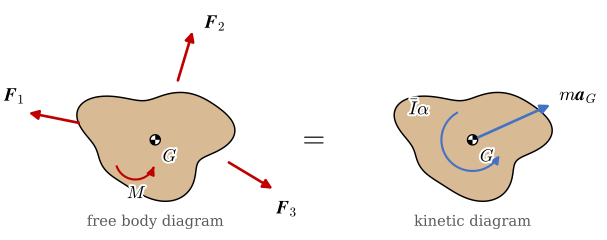
7.6.1 and 7.6.2 are the Newton-Euler equations of plane motion: two scalar equations for the translation and one for the rotation. They say that the external forces on the body are equivalent to the force \(m\bm a_G\) at \(G\) and the couple \(\bar I\alpha\). We draw that statement as two diagrams side by side (Figure 7.6.1): the free body diagram with the forces, and the kinetic diagram with \(m\bm a_G\) and \(\bar I\alpha\). Equating the two term by term, in any direction and about any point, gives the equations of motion.
The moment of inertia \(\bar I = \int r^2\,dm\) measures how far the mass lies from the axis. Mass far out counts with the square of its distance, which is why a flywheel puts its mass in the rim. For bodies of uniform density the integral is done once and tabulated. A slender bar of length \(L\) has the mass \(dm = (m/L)\,dx\) per element, a disc of radius \(R\) has \(dm = m/(\pi R^2)\,2\pi r\,dr\) per ring, and a thin ring has all its mass at \(r = R\):
\[ \bar I_{\text{bar}} = \int_{-L/2}^{L/2} x^2\,\frac{m}{L}\,dx , \qquad \bar I_{\text{disc}} = \int_0^R r^2\,\frac{2m}{R^2}\,r\,dr , \qquad \bar I_{\text{ring}} = mR^2 . \]
m, L, R, x, s = sp.symbols('m L R x s', positive=True)
I_bar = sp.integrate(x**2*m/L, (x, -L/2, L/2))
I_disc = sp.integrate(s**2*2*m/R**2*s, (s, 0, R))The integrals give
\[ \begin{aligned}\bar I_{\text{bar}} &=\dfrac{L^{2} m}{12}\\ \bar I_{\text{disc}} &=\dfrac{R^{2} m}{2}\\ \bar I_{\text{ring}} &=R^{2} m\end{aligned} \]
A ring has twice the moment of inertia of a disc of the same mass and radius, since all its mass sits at the rim.
7.6.2 takes moments about \(G\). Often another point is better: a pin whose reaction is unknown, so that the reaction drops out of the moment equation. With \(\bm r_{Pi} = \bm r_{PG} + \bm r_{Gi}\), the moment of the external forces about any point \(P\) is the moment of the kinetic diagram about \(P\),
\[ \sum M_P = \bar I\alpha + \bigl(\bm r_{PG}\times m\bm a_G\bigr)\cdot\bm e_z . \tag{7.6.3}\]
The second term is the moment of the force \(m\bm a_G\) in Figure 7.6.1, taken about \(P\).
When the body turns about a fixed pin at \(P\), the centre of mass moves on a circle of radius \(d = |\bm r_{PG}|\). Its acceleration has the tangential part \(d\alpha\), with the lever arm \(d\), and the normal part \(d\omega^2\), which points at \(P\) and has no moment about it. 7.6.3 becomes
\[ \sum M_P = \bigl(\bar I + m d^2\bigr)\alpha = I_P\,\alpha , \qquad I_P = \bar I + m d^2 . \tag{7.6.4}\]
The relation \(I_P = \bar I + md^2\) is the parallel axis theorem, also called Steiner’s theorem. A slender bar pinned at its end has \(I_O = mL^2/12 + m(L/2)^2 = mL^2/3\).
The moment of inertia is often given through the radius of gyration \(k_P\), defined by \(I_P = m k_P^2\). It is the distance from the axis at which the whole mass, concentrated in one point, would have the same moment of inertia. Euler wrote the moment of inertia in this form, \(Mkk\), in the same chapter of 1765 that defined it. For the bar about its end, \(k_O = L/\sqrt 3 \approx 0.58L\). Tables list \(k\) for standard shapes and catalogues list it for flywheels and rotors, since it is a length and compares directly with the size of the part.
The kinetic energy of the body is the sum over its particles. With \(\dot{\bm r}_i = \bm v_G + \bm\omega\times\bm r_{Gi}\),
\[ T = \sum \tfrac{1}{2}m_i\,\dot{\bm r}_i\cdot\dot{\bm r}_i = \tfrac{1}{2}m v_G^2 + \bm v_G\cdot\Bigl(\bm\omega\times\sum m_i\bm r_{Gi}\Bigr) + \tfrac{1}{2}\sum m_i\,r_{Gi}^2\,\omega^2 . \]
The middle term vanishes, again because \(\sum m_i\bm r_{Gi} = \bm 0\), and
\[ T = \tfrac{1}{2}m v_G^2 + \tfrac{1}{2}\bar I\omega^2 . \tag{7.6.5}\]
The kinetic energy is that of the translation of the centre of mass plus that of the rotation about it. For a body turning about a fixed pin \(P\), \(v_G = d\omega\) and the parallel axis theorem combine the two terms into \(T = \tfrac{1}{2}I_P\,\omega^2\). With 7.6.5, the energy balance \(T_1 + V_1 + U'_{1\to2} = T_2 + V_2\) of Work, energy and power applies to rigid bodies unchanged. A moment \(M\) does the work \(\int M\,d\theta\), and a damping moment \(-c\dot\theta\) takes energy out at the rate \(c\dot\theta^2\).
A uniform bar of length \(L = 0.6\) m and mass \(m = 1.2\) kg swings about a pin at its end \(O\) (Figure 7.6.2). Friction in the pin is modelled as a viscous moment \(-c\dot\theta\) against the rotation, with \(c = 0.02\) N·m·s. The bar is released from rest in the horizontal position, \(\theta_0 = 90^\circ\). Find the motion, the angular velocity at the bottom of the first swing, and the force in the pin.
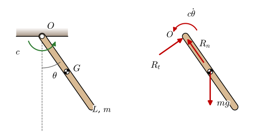
The pin is fixed, so we take moments about \(O\) with 7.6.4. The pin force has no moment about \(O\), and the weight acts at \(G\), a distance \(r_G = L/2\) from \(O\), with the lever arm \(r_G\sin\theta\):
\[ -mg\,r_G\sin\theta - c\dot\theta = I_O\,\ddot\theta , \qquad I_O = \frac{mL^2}{3} = m k_O^2 . \]
Dividing by \(I_O\),
\[ \ddot\theta = -\frac{g\,r_G}{k_O^2}\sin\theta - \frac{c}{m k_O^2}\,\dot\theta , \qquad \theta(0) = \frac{\pi}{2} , \quad \dot\theta(0) = 0 . \tag{7.6.6}\]
Compare the simple pendulum of Particle kinetics, a point mass on a massless rod of length \(\ell\), with \(\ddot\theta = -(g/\ell)\sin\theta\). The bar moves like a simple pendulum of the equivalent length
\[ \ell_{\text{eq}} = \frac{k_O^2}{r_G} = \frac{L^2/3}{L/2} = \frac{2}{3}L , \]
shorter than the bar, because the mass near the pin turns with the rest but adds little to the moment of gravity.
The pin force follows from 7.6.1. The centre of mass moves on a circle of radius \(r_G\), with the normal acceleration \(r_G\dot\theta^2\) towards \(O\) and the tangential acceleration \(r_G\ddot\theta\). Projecting on the directions of \(R_n\) and \(R_t\) in Figure 7.6.2,
\[ \begin{aligned} R_n - mg\cos\theta &= m\,r_G\,\dot\theta^2 , \\ R_t - mg\sin\theta &= m\,r_G\,\ddot\theta . \end{aligned} \]
c, g, r_G, k_O = sp.symbols('c g r_G k_O', positive=True)
th, thd, thdd, R_n, R_t = sp.symbols(r'theta \dot\theta \ddot\theta R_n R_t', real=True)
thdd_eq = -g*r_G/k_O**2*sp.sin(th) - c/(m*k_O**2)*thd
pin = sp.solve([sp.Eq(R_n - m*g*sp.cos(th), m*r_G*thd**2),
                sp.Eq(R_t - m*g*sp.sin(th), m*r_G*thdd_eq)], [R_n, R_t], dict=True)[0]
bar_vals = {r_G: L/2, k_O: L/sp.sqrt(3)}
R_t_bar = sp.simplify(pin[R_t].subs(bar_vals).subs(c, 0))
Solving for the two components, and inserting \(r_G = L/2\) and \(k_O^2 = L^2/3\) for the bar without friction in the tangential one,
\[ \begin{aligned}R_n &=\dot\theta^{2} m r_{G} + g m \cos{\left(\theta \right)}\\ R_t &=- \dfrac{\dot\theta c r_{G}}{k_{O}^{2}} + m \left(g \sin{\left(\theta \right)} - \dfrac{g r_{G}^{2} \sin{\left(\theta \right)}}{k_{O}^{2}}\right)\\ R_t\big|_{\text{bar},\ c=0} &=\dfrac{g m \sin{\left(\theta \right)}}{4}\end{aligned} \]
The tangential pin force is only a quarter of the weight’s component across the bar, \(\tfrac14 mg\sin\theta\). A point mass at the end of a massless rod would need no tangential force at all; the bar needs a little, because its inner part would swing faster on its own than the pin lets it.
We integrate 7.6.6 with Euler-Cromer, without friction and with it, over six seconds:
\[ \begin{aligned} \dot\theta_{i+1} &= \dot\theta_i + \Delta t\,\ddot\theta(\theta_i, \dot\theta_i) , \\ \theta_{i+1} &= \theta_i + \Delta t\,\dot\theta_{i+1} . \end{aligned} \]
Each run checks itself with energy, as in Work, energy and power. With the zero level of the potential energy at \(O\), the total energy is
\[ E = \tfrac{1}{2}I_O\,\dot\theta^2 - mg\,r_G\cos\theta . \]
Without friction \(E\) must stay constant. With friction it must fall by exactly the work the friction moment has done, \(\int_0^t c\,\dot\theta^2\,dt\).
def swing(c=0.0, L=0.6, m=1.2, g=9.81, theta0=np.pi/2, T=6.0, dt=1e-4):
    r_G, I_O = L/2, m*L**2/3
    n = int(T/dt)
    t, theta, omega = np.arange(n)*dt, np.zeros(n), np.zeros(n)
    theta[0] = theta0
    for i in range(n - 1):
        alpha = -(m*g*r_G*np.sin(theta[i]) + c*omega[i])/I_O
        omega[i + 1] = omega[i] + dt*alpha
        theta[i + 1] = theta[i] + dt*omega[i + 1]
    E = I_O*omega**2/2 - m*g*r_G*np.cos(theta)
    W_c = np.concatenate([[0.0], np.cumsum(c*omega[1:]**2*dt)])     # work done by friction
    return t, theta, omega, E, W_c

t0, th0, om0, E0, _ = swing(c=0.0)
t1, th1, om1, E1, W1 = swing(c=0.02)fig, axes = plt.subplots(2, 1, figsize=(6, 5), sharex=True)
axes[0].plot(t0, np.degrees(th0), color='C0', lw=1.5, label='$c = 0$')
axes[0].plot(t1, np.degrees(th1), color='C3', lw=1.5, label=r'$c = 0.02$ N$\cdot$m$\cdot$s')
axes[0].set_ylabel(r'$\theta$ [deg]'); axes[0].set_ylim(-90, 90); axes[0].grid(alpha=0.3)
axes[0].legend(loc='lower center', bbox_to_anchor=(0.5, 1.0), fontsize=9, ncol=2, frameon=False)
axes[1].plot(t1, E1[0] - E1, color='C3', lw=2.5, alpha=0.5, label='energy lost, $E_0 - E$')
axes[1].plot(t1, W1, 'k--', lw=1.2, label=r'friction work, $\int c\dot\theta^2\,dt$')
axes[1].set_xlabel('$t$ [s]'); axes[1].set_ylabel('[J]'); axes[1].grid(alpha=0.3)
axes[1].set_xlim(0, 6); axes[1].set_ylim(0, 2.2); axes[1].legend(loc='upper left', fontsize=9)
end_ticks(fig)
plt.tight_layout(); plt.show()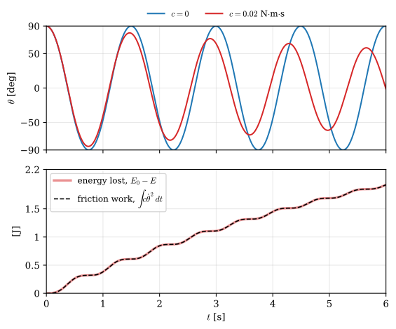
drift0 = np.max(np.abs(E0 - E0[0]))/(1.2*9.81*0.3)
mismatch = np.max(np.abs((E1[0] - E1) - W1))
The friction moment takes about 1.9 J out of the swing in six seconds, and the amplitude falls from \(90^\circ\) to about \(65^\circ\). The energy lost and the friction work lie on top of each other. Measured against the scale \(mg\,r_G\),
\[ \begin{aligned}\max\frac{|E - E_0|}{mg\,r_G}\Big|_{c=0} &\approx0.00022\\ \max\Bigl|(E_0 - E) - \int c\dot\theta^2\,dt\Bigr|\Big|_{c=0.02} &\approx0.00075~\text{J}\end{aligned} \]
Both checks are at the level of the time step’s error, so the integration and the model of the friction agree.
The angular velocity at the bottom follows without the time history. Without friction, the energy balance between the release and the bottom, with \(T = \tfrac12 I_O\omega^2\) from 7.6.5, gives
\[ 0 + 0 = \tfrac{1}{2}I_O\,\omega_b^2 - mg\,r_G \quad\Longrightarrow\quad \omega_b = \sqrt{\frac{2mg\,r_G}{I_O}} = \sqrt{\frac{3g}{L}} , \]
and at the bottom \(\theta = 0\) and \(\ddot\theta = 0\), so the pin carries
\[ R_n = mg + m\,r_G\,\omega_b^2 = mg + m\frac{L}{2}\frac{3g}{L} = \tfrac{5}{2}mg . \]
omega_b = np.sqrt(3*9.81/0.6)
omega_sim = np.max(np.abs(om0[t0 < 1.0]))
With the numbers of the example, against the largest angular velocity of the first swing in the simulation without friction,
\[ \begin{aligned}\omega_b = \sqrt{3g/L} &=7.00~\text{rad/s}\\ \max|\dot\theta|_{\text{simulation}} &=7.00~\text{rad/s}\\ R_n = \tfrac{5}{2}mg &=29.43~\text{N}\end{aligned} \]
The pin carries two and a half times the weight of the bar at the bottom of the swing, whatever the length of the bar.
Model the bar as a 600 mm aluminium bar with a mass of 1.2 kg, a hinge at one end, gravity, and a rotational damper of 0.02 N·m·s on the hinge. Run it for six seconds from the horizontal position and plot the angle and the hinge force. The angle should follow the red curve above, and the hinge force at the first bottom should be close to 29.4 N. If it is not, check the mass properties first.
A cart of mass \(M = 10\) kg rolls without friction on a horizontal rail and is held by a spring of stiffness \(k = 270\) N/m to the wall (Figure 7.6.3). A uniform bar of mass \(m = 1\) kg and length \(L = 0.6\) m hangs from a pin \(O\) on the cart. The spring is unstretched at \(x = 0\). The cart is held at \(x = 0\), the bar is lifted to \(\theta_0 = 20^\circ\), and both are released from rest. Find the motion of the cart and the bar.
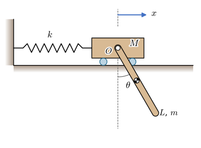
The system has two degrees of freedom, \(x\) and \(\theta\). The spring stiffness is chosen so that the cart, carrying the mass of the bar, would oscillate at the same frequency as the bar swinging on a fixed pin. That choice makes the two motions trade energy with each other, which we will see in the result.
The pin \(O\) moves with the cart, and the centre of mass of the bar lies \(L/2\) below it along the bar,
\[ \bm r_G = \begin{bmatrix} x + \tfrac{L}{2}\sin\theta \\ -\tfrac{L}{2}\cos\theta \end{bmatrix} , \]
whose second time derivative is the acceleration \(\bm a_G\) in 7.6.1.
We cut the system at the pin (Figure 7.6.4). The cart pulls on the bar with the pin force \(\bm R = [R_x,\ R_y]^\mathsf{T}\) and the bar pulls back on the cart with \(-\bm R\). On the cart act the spring force \(-kx\), its weight, the normal force \(N\) of the rail and \(-\bm R\); on the bar act \(\bm R\) and its weight.
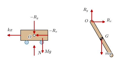
The cart only translates, along the rail. The bar translates and rotates, and its moment equation about \(G\) uses the arm \(\bm r_{GO} = [-\tfrac{L}{2}\sin\theta,\ \tfrac{L}{2}\cos\theta]^\mathsf{T}\) from \(G\) to the pin:
\[ \begin{aligned} \text{cart, } x:&\quad M\ddot x = -kx - R_x , \\ \text{cart, } y:&\quad 0 = N - Mg - R_y , \\ \text{bar, } x:&\quad m\,a_{Gx} = R_x , \\ \text{bar, } y:&\quad m\,a_{Gy} = R_y - mg , \\ \text{bar, about } G:&\quad \bar I\,\ddot\theta = (\bm r_{GO}\times\bm R)\cdot\bm e_z = -\tfrac{L}{2}\sin\theta\,R_y - \tfrac{L}{2}\cos\theta\,R_x , \end{aligned} \]
with \(\bar I = mL^2/12\). These are five equations in the five unknowns \(\ddot x\), \(\ddot\theta\), \(R_x\), \(R_y\) and \(N\).
t = sp.symbols('t', real=True)
M, k = sp.symbols('M k', positive=True)
xf, thf = sp.Function('x')(t), sp.Function('theta')(t)
Rx, Ry, N = sp.symbols('R_x R_y N', real=True)
xs, xd, xdd, ths, thd2, thdd2 = sp.symbols(r'x \dot{x} \ddot{x} theta \dot\theta \ddot\theta', real=True)
named = {xf.diff(t, 2): xdd, thf.diff(t, 2): thdd2, xf.diff(t): xd, thf.diff(t): thd2,
         xf: xs, thf: ths}

rr_G = sp.Matrix([xf + L/2*sp.sin(thf), -L/2*sp.cos(thf)])
aa_G = rr_G.diff(t, 2).subs(named)
I_G = m*L**2/12
eqs = [sp.Eq(M*xdd, -k*xs - Rx),
       sp.Eq(0, N - M*g - Ry),
       sp.Eq(m*aa_G[0], Rx),
       sp.Eq(m*aa_G[1], Ry - m*g),
       sp.Eq(I_G*thdd2, -L/2*sp.sin(ths)*Ry - L/2*sp.cos(ths)*Rx)]
cart_sol = sp.solve(eqs, [xdd, thdd2, Rx, Ry, N], dict=True)[0]
acc_x, acc_th = sp.simplify(cart_sol[xdd]), sp.simplify(cart_sol[thdd2])
Solving the five equations for the two accelerations gives the equations of motion of the system,
\[ \begin{aligned}\ddot x &=\dfrac{4 L \dot\theta^{2} m \sin{\left(\theta \right)} + 3 g m \sin{\left(2 \theta \right)} - 8 k x}{2 \left(4 M + 3 m \sin^{2}{\left(\theta \right)} + m\right)}\\[1.5ex] \ddot\theta &=\dfrac{3 \left(- \dfrac{L \dot\theta^{2} m \sin{\left(2 \theta \right)}}{2} - 2 M g \sin{\left(\theta \right)} - 2 g m \sin{\left(\theta \right)} + 2 k x \cos{\left(\theta \right)}\right)}{L \left(4 M + 3 m \sin^{2}{\left(\theta \right)} + m\right)}\end{aligned} \]
Both accelerations depend on both coordinates: the cart’s acceleration on the swing of the bar through \(\theta\) and \(\dot\theta^2\), and the bar’s on the spring force through \(x\). That is the coupling. The pin force has done its job of connecting the two bodies and has dropped out. The chapter on Euler-Lagrange arrives at the same two equations without ever writing it down.
With \(\ddot x(x, \theta, \dot\theta)\) and \(\ddot\theta(x, \theta, \dot\theta)\) from Step 2, Euler-Cromer advances both coordinates together,
\[ \begin{aligned} \dot x_{i+1} &= \dot x_i + \Delta t\,\ddot x_i , & x_{i+1} &= x_i + \Delta t\,\dot x_{i+1} , \\ \dot\theta_{i+1} &= \dot\theta_i + \Delta t\,\ddot\theta_i , & \theta_{i+1} &= \theta_i + \Delta t\,\dot\theta_{i+1} . \end{aligned} \]
There is no friction, so the total energy must stay constant. It is the kinetic energy of the cart and of the bar, 7.6.5, plus the energy of the spring and the potential energy of the bar,
\[ E = \tfrac{1}{2}M\dot x^2 + \tfrac{1}{2}m\,|\bm v_G|^2 + \tfrac{1}{2}\bar I\dot\theta^2 + \tfrac{1}{2}kx^2 - mg\frac{L}{2}\cos\theta . \]
cart_vals = {M: 10, m: 1, L: sp.Rational(6, 10), k: 270, g: sp.Rational(981, 100)}
f_x = sp.lambdify((xs, ths, xd, thd2), acc_x.subs(cart_vals))
f_th = sp.lambdify((xs, ths, xd, thd2), acc_th.subs(cart_vals))

def ride(theta0=np.radians(20), T=20.0, dt=1e-4):
    n = int(T/dt)
    t = np.arange(n)*dt
    x, th, v, w = (np.zeros(n) for _ in range(4))
    th[0] = theta0
    for i in range(n - 1):
        ax, ath = f_x(x[i], th[i], v[i], w[i]), f_th(x[i], th[i], v[i], w[i])
        v[i + 1], w[i + 1] = v[i] + dt*ax, w[i] + dt*ath
        x[i + 1], th[i + 1] = x[i] + dt*v[i + 1], th[i] + dt*w[i + 1]
    return t, x, th, v, w

tc, xc, thc, vc, wc = ride()
Mv, mv, Lv, kv, gv = 10.0, 1.0, 0.6, 270.0, 9.81
vGx, vGy = vc + Lv/2*np.cos(thc)*wc, Lv/2*np.sin(thc)*wc
Ec = (Mv*vc**2 + mv*(vGx**2 + vGy**2) + mv*Lv**2/12*wc**2 + kv*xc**2)/2 - mv*gv*Lv/2*np.cos(thc)
drift_c = np.max(np.abs(Ec - Ec[0]))/(Ec[0] + mv*gv*Lv/2)fig, axes = plt.subplots(3, 1, figsize=(6, 6.2), sharex=True)
axes[0].plot(tc, 100*xc, color='C0', lw=1)
axes[0].set_ylabel('$x$ [cm]'); axes[0].set_ylim(-4, 4)
axes[1].plot(tc, np.degrees(thc), color='C3', lw=1)
axes[1].set_ylabel(r'$\theta$ [deg]'); axes[1].set_ylim(-20, 20)
axes[2].plot(tc, 100*(Ec - Ec[0])/(Ec[0] + mv*gv*Lv/2), color='k', lw=1)
axes[2].set_ylabel(r'$\Delta E$ [%]'); axes[2].set_xlabel('$t$ [s]'); axes[2].set_ylim(-0.1, 0.1)
for a in axes: a.grid(alpha=0.3); a.set_xlim(0, 20)
end_ticks(fig)
plt.tight_layout(); plt.show()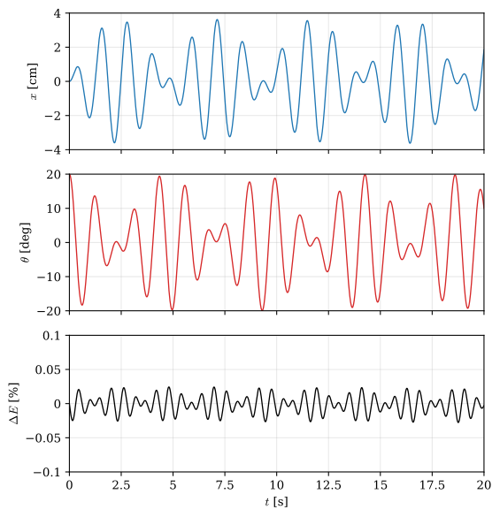
The bar starts with all the energy. Within about two seconds its swing has shrunk to a few degrees while the cart, which started at rest, oscillates by almost 4 cm; two seconds later the bar has taken the energy back. The exchange repeats as long as nothing damps it. The bottom plot is the energy drift, measured against the energy given to the system at the release,
\[ \begin{aligned}\max\frac{|E - E_0|}{mg\frac{L}{2}(1 - \cos\theta_0)} &\approx0.03~\%\end{aligned} \]
which confirms that the coupled integration conserves the energy it should.
The exchange is what a tuned mass damper exploits. A pendulum or a mass on a spring, tuned to the frequency of a structure, draws the vibration energy out of the structure and into itself, where a damper turns it into heat. Taipei 101 carries a 660-tonne pendulum for this purpose.
The plane motion of this chapter turns the body about the \(z\) axis only, and the one number \(\bar I\) describes its inertia. A body that turns about another axis, a crankshaft or a wheel mounted askew on its shaft, needs more. The angular momentum is the same sum as before, \(\bm H_G = \sum \bm r_{Gi}\times m_i(\bm\omega\times\bm r_{Gi})\), but with \(\bm r\times(\bm\omega\times\bm r) = (\bm r\cdot\bm r)\,\bm\omega - (\bm r\cdot\bm\omega)\,\bm r\) in three dimensions it becomes \(\bm H_G = \bar{\bm I}\bm\omega\), where the symmetric inertia matrix holds the moments of inertia about the three axes through \(G\) on its diagonal and the products of inertia off it,
\[ \bar{\bm I} = \int \bigl((\bm r\cdot\bm r)\,\bm 1 - \bm r\bm r^\mathsf{T}\bigr)\,dm = \int \begin{bmatrix} y^2 + z^2 & -xy & -xz \\ -xy & z^2 + x^2 & -yz \\ -xz & -yz & x^2 + y^2 \end{bmatrix} dm , \tag{7.6.7}\]
with \(\bm r = [x, y, z]^\mathsf{T}\) measured from \(G\). The angular momentum points along \(\bm\omega\) only when \(\bm\omega\) is an eigenvector of \(\bar{\bm I}\) (Chapter 3.14). A symmetric matrix has three such directions at right angles to each other, the principal axes of the body, and its eigenvalues are the principal moments of inertia.
A flat body in the \(xy\) plane has \(z = 0\) throughout, so the third row of \(\bar{\bm I}\) is \([0,\ 0,\ \int(x^2 + y^2)\,dm]\). The \(z\) axis is a principal axis, and its entry is the \(\bar I = \int r^2\,dm\) of plane motion, which is why one number has been enough so far.
A slender uniform bar of length \(L\) and mass \(m\) lies in the \(xy\) plane at \(30^\circ\) to the \(x\) axis, with its centre of mass \(G\) at the origin (Figure 7.6.5). Find its inertia matrix about \(G\) and its principal axes.
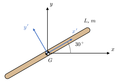
We measure the arc length \(s\) along the bar from \(G\), as for \(\bar I_{\text{bar}}\). The point at \(s\) lies at \(\bm r = s\,[\cos 30^\circ,\ \sin 30^\circ,\ 0]^\mathsf{T}\) and carries the mass \(dm = (m/L)\,ds\), so 7.6.7 becomes
\[ \bar{\bm I} = \int_{-L/2}^{L/2} \bigl((\bm r\cdot\bm r)\,\bm 1 - \bm r\bm r^\mathsf{T}\bigr)\,\frac{m}{L}\,ds . \]
rr = s*sp.Matrix([sp.cos(sp.pi/6), sp.sin(sp.pi/6), 0])
II = sp.integrate((rr.dot(rr)*sp.eye(3) - rr*rr.T)*m/L, (s, -L/2, L/2))
Every entry is \(mL^2/12\) times a product of the direction cosines,
\[ \bar{\bm I} = \left[\begin{matrix}\dfrac{L^{2} m}{48} & - \dfrac{\sqrt{3} L^{2} m}{48} & 0\\- \dfrac{\sqrt{3} L^{2} m}{48} & \dfrac{L^{2} m}{16} & 0\\0 & 0 & \dfrac{L^{2} m}{12}\end{matrix}\right] \]
The products of inertia are not zero, so \(x\) and \(y\) are not principal axes. The eigenvalues of \(\bar{\bm I}\), and its unit eigenvectors as the columns of \(\bm Q\), are
eig = II.eigenvects()          # [(lambda, multiplicity, [x, ...]), ...], here 0 first
lams = [lam for lam, mult, vecs in eig for _ in vecs]
QQ = sp.Matrix.hstack(*[xx/xx.norm() for lam, mult, vecs in eig for xx in vecs])
DD = sp.simplify(QQ.T*II*QQ)
\[ \begin{aligned}\lambda &= \left[\begin{matrix}0 & \dfrac{L^{2} m}{12} & \dfrac{L^{2} m}{12}\end{matrix}\right],\qquad \bm Q = \left[\begin{matrix}\dfrac{\sqrt{3}}{2} & - \dfrac{1}{2} & 0\\\dfrac{1}{2} & \dfrac{\sqrt{3}}{2} & 0\\0 & 0 & 1\end{matrix}\right]\\ \bm Q^\mathsf{T}\bar{\bm I}\bm Q &= \left[\begin{matrix}0 & 0 & 0\\0 & \dfrac{L^{2} m}{12} & 0\\0 & 0 & \dfrac{L^{2} m}{12}\end{matrix}\right]\end{aligned} \]
The first eigenvector points along the bar, the \(x'\) axis of Figure 7.6.5, with the principal moment zero: a slender bar has all its mass on that axis. The eigenvalue \(mL^2/12\) is double, and every direction perpendicular to the bar is principal with the moment of inertia \(\bar I_{\text{bar}}\); SymPy returns \(y'\) and \(z\). In the axes of the bar the matrix is diagonal, as for any symmetric matrix in Chapter 3.14. The trace is the same in both bases, \(mL^2/48 + mL^2/16 + mL^2/12 = mL^2/6\). The Mass Properties tool of SolidWorks lists both forms for a part: the inertia matrix about \(G\) in the axes of the model, and the principal axes with the principal moments.
The principal axes matter when the body spins. Let the bar turn about the \(x\) axis, as if welded askew to a shaft, with \(\bm\omega = \omega\,\bm e_x\):
omega = sp.symbols('omega', positive=True)
HH_G = II*sp.Matrix([omega, 0, 0])
angle_H = sp.acos(HH_G[0]/HH_G.norm())
\[ \bm H_G = \bar{\bm I}\bm\omega = \left[\begin{matrix}\dfrac{L^{2} m \omega}{48}\\- \dfrac{\sqrt{3} L^{2} m \omega}{48}\\0\end{matrix}\right],\qquad \angle(\bm H_G, \bm\omega) = 60^\circ \]
The angular momentum stands at \(60^\circ\) to the shaft, perpendicular to the bar, and turns with the bar about the shaft. A turning \(\bm H_G\) needs a moment, \(\sum\bm M_G = \dot{\bm H}_G\), which the bearings must supply at every revolution although \(G\) stays at rest and the speed is constant. This is dynamic imbalance. Balancing a rotor puts its centre of mass on the shaft and one of its principal axes along it, so that \(\bm H_G\) points along \(\bm\omega\) and stands still.
The lid mechanism applies the same Newton-Euler equations to three bodies joined by four pins, with twelve unknowns where the cart needed five. The pin forces there are wanted, for the design of the pins. When they are not, virtual work and the Euler-Lagrange equations give the equations of motion without them.
Meriam, Kraige and Bolton treat the plane kinetics of rigid bodies, with the moment equation about an arbitrary point and the work-energy relation, in chapter 6 of their Dynamics [1].