Two printed halves of a tensile bar are glued over one face of 24 × 8 mm and pulled apart. How much force does the joint take, and where does it break? The workshop’s glues, a cyanoacrylatesv. cyanoakrylat, superlim and a construction adhesivesv. bygglim, come without strength data for bonding PLA, so in the glue labsv. Lim-labb we measure it. The specimen is drawn to load the glue in pure shear, and it does not quite: the two tongues pull past each other with an offset, and the offset opens the ends of the glue line in peel. The theory is in Adhesive joints and Gluing printed parts.
The specimen
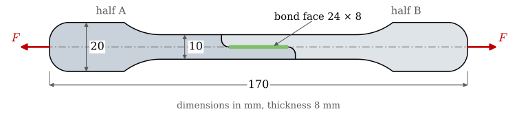
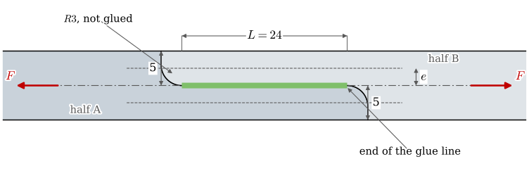
The specimen V2 (Figure 9.22.1) has the outline of the tensile bar used for material testing on the same machine, cut in two. Each half ends in a tongue half as wide as the bar, and the tongues overlap side by side. Only the face between the two fillets is glued, 24 mm long and as high as the print is thick, so the glue is loaded along its plane, in shear. The fillets and the end faces stay dry.
(a) The specimen from above, the two halves in two shades, the bond face in green.
(b) The overlap enlarged. The pull acts along the centre line, each tongue along its own centre line at the offset \(e\) from it.
Figure 9.22.1: The lap-shear specimen V2, drawn from its CAD model. Dimensions in mm.
Table 9.22.1: The specimen V2 as drawn. A print does not hold these sizes: measure \(b\) and \(L\) on every specimen.
Quantity
Value
length, two halves together
170 mm
width of the grip ends
20 mm
width of the middle part
10 mm
thickness \(b\) (the height of the bond face)
8 mm
tongue width \(t\)
5 mm
length \(L\) of the bond face
24 mm
bonded area \(A = bL\)
192 mm²
fillet radius at each end of the bond face
3 mm
Download the geometry, Provstav_V2.step, from the Lim-labb page on Canvas, and print both halves flat on the bed with 100 % infill. The halves fit together without a gap in CAD, so the glue line is as thin as the print lets it be.
Glues and safety
Two glues are approved for the workshop: a cyanoacrylate (Biltema superlim) and a construction adhesive (Biltema bygglim). Construction adhesives of modified silicone or MS polymer, such as Tec7 or Biltema Multibond, are interesting too. Epoxy needs the thermoset training and is not supported in the lab. Victor knows which glues the workshop supports and where to glue; ask him, or Mirza, when in doubt or for help with the gluing.
WarningGlue safely
Glue in the fume cupboard (dragskåpsv. dragskåp) with gloves and eye protection. Cyanoacrylate bonds skin in seconds: keep it off your fingers and away from your face. Other glues than the approved ones are tested at your own risk, after asking Victor. How this lab goes decides how the workshop handles glue in future courses.
Gluing
Measure the bond face of every half with a caliper: its length \(L\) and its height \(b\).
Wipe the bond faces clean; the glue holds only to a surface free from grease [1]. Sanding the faces is a variable to test: on printed ABS it gave stronger joints than cleaning alone [2].
Put glue on the bond face of one half only, not on the fillets or the end faces.
Press the halves together and hold them aligned until the glue has fixed, a few seconds for cyanoacrylate [1] and hours for a construction adhesive [3]. Wipe off glue that squeezes out onto the fillets.
Let the glue cure as its maker says before pulling: 24 to 72 h for cyanoacrylate [1]; a construction adhesive cures from the air inwards, about 6 mm a day for Tec7 [3]. How long the glue needs to reach its full strength is itself a question the machine can answer.
Write down for every specimen: the glue, the surface preparation, the date and time of gluing and of testing, and the printer and filament.
A butt joint, glued end to end, is a different load case and can be tested as well: which is stronger?
The tensile test machine
Book the machine in the booking schedule. Ask Mirza for a walkthrough of the machine; groups are gathered for it, and before it you watch the recording of Figure 9.22.2.
Figure 9.22.2: The tensile test machine and its program, a live recording from 2026-09-01 (in Swedish).
The machine is run from the program UTM Control on your own laptop (Windows 10 or 11). To install it, open PowerShell (Start menu, type powershell) and paste this line:
It downloads the program, sets up Python and puts an icon, UTM Control, on the desktop. Two USB cables go to the laptop, one for the camera and one for the machine. The camera needs a USB 3 port, the blue one, and does not work through a hub. Double-click UTM Control to start.
The program saves each test as a CSV file whose comment lines start with # (Table 9.22.2; UTM repository).
Table 9.22.2: The columns of a UTM Control CSV file.
Column
Meaning
Time_s
time [s]
Force_N
force [N]
Position_mm
crosshead position [mm]
DIC_Cauchy, DIC_True
strain between two marker dots, measured by the camera
L_px
distance between the dots [pixels]
Speed_mm_s
crosshead speed [mm/s]
Procedure
Clamp the grip ends of the glued specimen in the machine, the specimen straight.
Enter the bonded area you measured, \(bL\), in the program.
To measure how far the joint slides before it lets go, put two small marker dots on the specimen, one on each side of the overlap, and calibrate their distance in the program. Without the dots the crosshead position measures the joint, the specimen and the machine together.
Pull to failure at a constant speed, and note the speed.
Photograph both fracture faces and note where the joint failed: in the interface (bare plastic on one face), in the glue (glue left on both faces), or in the plastic, in a tongue or at a fillet.
Save the CSV with the glue and the specimen number in its name.
Test at least three specimens per glue: printed parts scatter, and one curve says little.
What the theory predicts
Divided by the bonded area, the largest force gives the nominal shear strength of the joint,
the value a data sheet reports from a lap-shear test. Two things make the true load case differ from that uniform shear.
The first is the offset. Near the end of the glue line one tongue carries all of the force, along its own centre line, \(e = t/2 = 2.5\) mm from the line of the pull (Figure 9.22.1 (b)). The tongue is then bent by \(Fe\) as well as pulled, and the same moment opens the end of the glue line in peel, as in a single lap joint (Adhesive joints). In the tongue’s section \(t \times b\) the largest stress is
The clamped grips hold back part of the moment, so this is an upper bound. With the yield strength of PLA printed flat, 51 MPa [4], the tongue yields at
Code
b, L, t =8.0, 24.0, 5.0# print thickness, length of the bond face, tongue width [mm]A_bond = b*L # bonded area [mm^2]e = t/2# offset of a tongue's centre line from the line of the pull [mm]k_tongue =1+6*e/t # peak stress in the tongue in units of F/(b t), @eq-gl-tongueR_e_PLA =51.0# yield strength of PLA printed flat [MPa], Prusament data sheetF_tongue = R_e_PLA*b*t/k_tongue # force at which the tongue yields next to the glue line [N]tau_tongue = F_tongue/A_bond # the nominal shear stress at that force [MPa]
A glue line that holds more than about 2.7 MPa nominal shear therefore does not break first: the tongue does, and the test then measures the PLA and the offset, not the glue. Where the specimen broke tells which of the two we measured.
The second is shear lag. By the shear-lag model, the glue line carries load over a length of about
at each end, with the tongue width \(t\) as the adherend thickness, the modulus \(E\) of the print, and the thickness \(h\) and shear modulus \(G\) of the glue line (9.20.8). Neither glue states its shear modulus, so we compare a rigid glue, with the \(G = 1\) GPa assumed for the epoxy of Example 4, with the construction adhesive, \(G \approx 0.67\) MPa from the modulus of Tec7 [3]. The glue line thicknesses are guesses; measure yours on a broken specimen.
Code
E_PLA =2300.0# modulus of PLA printed flat [MPa], Prusament data sheetglues = { # G [MPa], h [mm]: assumed, replace with your own values'rigid glue': (1000.0, 0.1),'construction adhesive': (2.0/3, 0.5),}lag = {}for name, (G, h) in glues.items(): w = np.sqrt(2*G/(h*E_PLA*t)) # @eq-pj-volkersen-ode [1/mm] u = w*L/2 lag[name] =dict(inv_w=1/w, peak=u/np.tanh(u), used=np.tanh(u)/u)
For the 24 mm bond face of the specimen the two glues give
Table 9.22.3: The shear-lag model for the lap-shear specimen, tongue width 5 mm, bond face 24 mm.
glue
\(1/\omega\) [mm]
\(\tau_\max/\tau_\text{nom}\)
share of the face that works
rigid glue
0.76
15.8
6 %
construction adhesive
65.67
1.0
99 %
A rigid glue loads the first millimetre at each end of the face, peaks at about sixteen times the nominal stress there, and fails from the ends; its \(\tau_\text{nom}\) belongs to this specimen and not to the glue. The construction adhesive loads all of the face evenly, so its \(\tau_\text{nom}\), peel at the ends aside, comes close to the shear strength of the glue.
Analysis with Python
The files in assets/gluelab are fictive recordings in the format of UTM Control, three specimens glued with cyanoacrylate (ca_*.csv) and three with construction adhesive (construction_*.csv), made so that the cells below run before you have data. Replace them with your own files. We read every file in the folder, skipping the comment lines:
Code
folder = pathlib.Path('assets/gluelab')runs = {f.stem: pd.read_csv(f, comment='#') for f insorted(folder.glob('*.csv'))}colour = {'ca': RED, 'construction': BLUE} # one colour per glue, from the file name
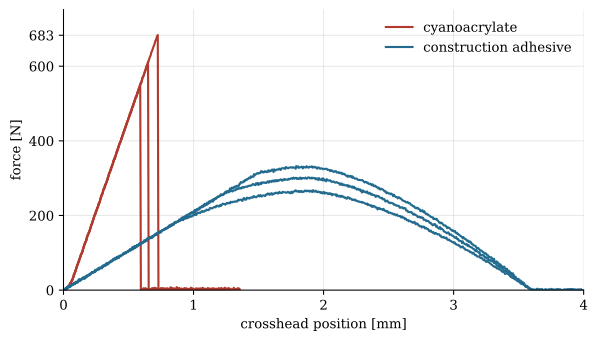
The force against the crosshead position shows the two kinds of joint at a glance (Figure 9.22.3).
Figure 9.22.3: Force against crosshead position for the fictive recordings. Red: cyanoacrylate, stiff and breaking at once. Blue: construction adhesive, soft and tearing gradually.
From each curve we take the largest force, the nominal shear stress by 9.22.1 with the area of Table 9.22.1 (use your measured \(bL\)), and the position at the largest force:
Code
res = pd.DataFrame([{'specimen': name, 'glue': name.split('_')[0],'F_max': d['Force_N'].max(),'u_at_F_max': d['Position_mm'][d['Force_N'].idxmax()]}for name, d in runs.items()])res['tau_nom'] = res['F_max']/A_bond # @eq-gl-tau-nom [MPa]summary = res.groupby('glue')['tau_nom'].agg(['mean', 'std', 'count'])
Table 9.22.4: Results of the fictive recordings.
specimen
\(F_\max\) [N]
\(\tau_\text{nom}\) [MPa]
position at \(F_\max\) [mm]
ca_1
612
3.19
0.65
ca_2
551
2.87
0.59
ca_3
683
3.56
0.72
construction_1
302
1.57
1.89
construction_2
268
1.39
1.92
construction_3
332
1.73
1.79
ca, mean ± std of 3
3.21 ± 0.34
construction, mean ± std of 3
1.57 ± 0.17
The fictive cyanoacrylate joints reach about 3.2 MPa nominal shear, above the 2.7 MPa at which 9.22.2 lets the tongue yield, so in a real test of such a glue look for a broken tongue before believing the number.
Questions
Work as a group, and let curiosity steer what you use the machine for. Answer with your measurements, your photographs and the theory above.
Where did each specimen fail: in the interface, in the glue, or in the plastic? Do we measure the glue?
What nominal shear strength does each glue reach, and how large is the spread between specimens?
How does the real load case differ from pure shear? Compare \(F_\max\) with the force at which 9.22.2 lets the tongue yield, and look for signs of peel at the ends of the glue line.
Estimate \(1/\omega\) for your glue with the thickness of the glue line you measured on a broken specimen. Would a 48 mm long bond face carry twice the load?
How far does the joint slide before it lets go? Use the marker dots on each side of the overlap.
Does the pulling speed change the result?
What do the data sheets say? Loctite 401, a cyanoacrylate, gives 7.5 MPa lap-shear strength on ABS [1]; Tec7 gives a tensile strength of 2.8 MPa after 7 days [3]. How do your values compare, and why might they differ?
How long does the glue take to reach its full strength?
Is a butt joint stronger or weaker than the lap?
When is each glue useful for a printed part, and when would you choose a screw instead?
Presentation
When you are done, tell us that you want to present. Give a short, simple presentation of what you found; we ask curious questions. A sincere attempt passes. Present well before the course ends, not in the exam week.
Frascio M, Mandolfino C, Moroni F, Jilich M, Lagazzo A, Pizzorni M, et al. Appraisal of surface preparation in adhesive bonding of additive manufactured substrates. International Journal of Adhesion and Adhesives 2021;106:102802. https://doi.org/10.1016/j.ijadhadh.2020.102802.