10.10 Lithium polymer batteries
The car runs on a three-cell lithium polymer battery, a 3S LiPo. It is the most energetic part on the car. A short circuit across its terminals can deliver several hundred amperes, enough to melt a wire, and a cell that is overcharged, punctured or discharged too deep can catch fire. The same pack is perfectly safe when we respect a handful of voltage limits and wire the car so that one fuse and one switch stand between the battery and everything else.
This chapter first gives the rules for handling the pack and the steps for building the car’s power chain: battery, XT60 connector, fuse, main switch and rail. The explanations of the numbers behind the rules come after the guide.
- Charge only in the LiPo charger, in balance mode, inside the fire-safe bag, and never leave a charging pack unattended.
- Never discharge below 3.0 V per cell (9.0 V for the pack). The car cuts off at 9.6 V under load.
- A swollen, dented or punctured pack is retired. Do not charge it and do not use it.
- Disconnect the pack from the car when you stop working. A switched-off car is not a disconnected car.
- Never let the bare ends of the battery leads touch, and never cut both leads at once.
The Guide
Before every use
- Look at the pack. The cells must be flat and the wrap intact. A pack that has puffed up like a pillow is swollen and is retired (see Swelling).
- Check the leads and the XT60 connector for cracked insulation and loose solder joints.
- Measure the pack voltage with the multimeter on the XT60 contacts, red probe on the positive contact. A healthy 3S pack reads between about 11.1 V (storage) and 12.6 V (full). Below 9.6 V the pack goes on the charger before it goes in the car.
Charging
- Put the pack in the fire-safe bag on a non-flammable surface, away from anything that burns.
- Connect both the main lead and the white balance connector to the charger. The balance connector of a 3S pack has four wires.
- Select the LiPo program (4.20 V per cell, not LiHV or LiFe), balance charge, 3 cells (3S, 11.1 V). The charger checks the cell count it detects against the one we set and refuses to start if they differ. Never start a charge the charger complains about.
- Set the charge current to 1C, i.e. the capacity in ampere-hours: 2.2 A for a 2200 mAh pack. Use a higher current only if the pack’s label allows it.
- Start the charge and stay in the room. The charge ends by itself at 4.20 V per cell.
- Disconnect the pack when the charger reports that it is done.
Storage
A pack that will rest for more than a few days is stored at about 3.8 V per cell, 11.4 V for the pack. Most chargers have a storage program that charges or discharges the pack to this level. Store the pack in the fire-safe bag or the battery cabinet, at room temperature, and never fully charged in a warm place.
Building the power chain
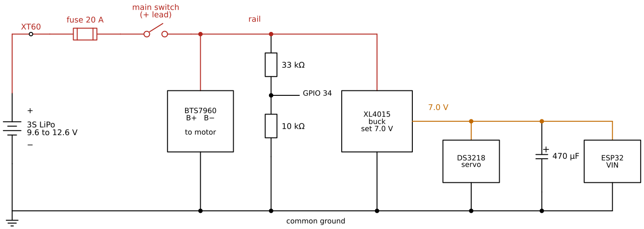
The car’s power chain is shown in Figure 10.10.1. The current leaves the positive terminal of the battery, passes the XT60 connector, the 20 A fuse and the main switch, and arrives at the rail. Three loads hang on the rail: the BTS7960 motor driver at its B+ terminal, the XL4015 buck converter that makes the 7.0 V for the servo and the ESP32, and the voltage divider that lets the ESP32 measure the battery. Every load returns its current through one common ground to the negative terminal.
- With the battery disconnected, solder the car’s half of the XT60 connector to a red and a black wire of 2.1 mm² (14 AWG, see Wire size). The housing is marked
+and−next to the contacts: red to+, and check against the battery’s half before soldering. Put heat shrink over both joints. - Put the fuse holder in the red wire as close to the XT60 as possible, then the main switch. The few centimetres from the XT60 to the fuse are the only part of the wiring the fuse does not protect, so keep them short.
- The far side of the switch is the rail. Connect the black wire to the ground point.
- Leave the fuse out and the switch off. Connect the battery, set the multimeter to DC volts and measure from the rail to ground: 0 V. Insert the 20 A fuse and measure again: still 0 V, since the switch is off. Switch on: the battery voltage. Switch off.
- Only now connect the loads to the rail, the motor driver first. The buck converter is connected and set before anything is connected to its output; that procedure is in Buck converters.
Solder, crimp and rewire only with the XT60 disconnected. The main switch interrupts the positive lead, but the wires from the XT60 through the fuse to the switch stay live as long as the pack is plugged in.
How It Works
The voltages of a lithium cell
A lithium polymer cell stores energy by moving lithium ions between two electrodes. Its voltage depends on how much charge it holds, and the useful window is narrow. A cell is full at 4.20 V, and charging it further plates metallic lithium on the electrode, which is how overcharged cells start fires. During discharge the voltage falls quickly from 4.20 V, stays a long time near the nominal 3.7 V printed on the label, and drops steeply again near the end. Below about 3.0 V the electrode chemistry is damaged: capacity is lost for good, the cell may swell, and recharging a deeply discharged cell is a fire risk. Manufacturers give 4.20 V as the charge voltage and 3.0 V as the discharge limit, and recommend about 3.8 V for storage, where the cell ages slowest.12
| Per cell | 3S pack | |
|---|---|---|
| Full (end of charge) | 4.20 V | 12.6 V |
| Nominal (label) | 3.7 V | 11.1 V |
| Storage | about 3.8 V | about 11.4 V |
| Cutoff under load, the car | 3.2 V | 9.6 V |
| Never below (at rest) | 3.0 V | 9.0 V |
Cells in series and the balance connector
One cell gives 3.7 V. Packs are named after the number of cells in series: a 1S pack is a single cell (the handheld remote uses one), and a 3S pack has three cells in series, so its voltages are three times those of a cell. The 11.1 V nominal of the car’s pack is \(3 \cdot 3.7~\text{V}\), and full charge is \(3 \cdot 4.20~\text{V} = 12.6~\text{V}\).
Cells in series carry the same current, but they are never quite equal. One cell may have slightly less capacity or slightly more self-discharge than the others. If the charger watched only the total voltage, it would stop at 12.6 V even if the cells sat at 4.25, 4.20 and 4.15 V, and the first cell would be overcharged. Over many cycles the difference grows. The balance connector is the small white plug with one wire to each junction between the cells: \(n + 1 = 4\) wires for a 3S pack. Through it the charger measures every cell and bleeds charge from the highest ones until all three end at 4.20 V. Balance charging is therefore the only safe way to charge a pack with more than one cell.
Capacity and C rating
The label of a pack gives its capacity in milliampere-hours, e.g. 2200 mAh: the charge the pack delivers from full to empty, here 2.2 A for one hour or 22 A for six minutes. The energy stored is the capacity times the nominal voltage,
\[ E = Q V_\text{nom} = 2.2 \cdot 11.1~\text{Wh} = 24.4~\text{Wh}. \]
The C rating tells how fast the pack may be discharged, as a multiple of its capacity. The maximum continuous current is
\[ I_\text{max} = C \, Q, \]
where the capacity \(Q\) is written in ampere-hours and the result comes out in amperes. Take a pack labelled 2200 mAh 3S 30C (read the label of your own pack; the numbers here are an example). It may deliver \(30 \cdot 2.2~\text{A} = 66~\text{A}\), far more than the car asks for. The C ratings printed on hobby packs are generous, so we treat them as an upper bound and not as a design value. What matters for the car is that even a modest pack can deliver much more current than the wires, the connector and the motor driver can carry. The fuse, not the battery, has to set the limit.
The same numbers estimate the driving time. If the car draws 5 A on average, a 2200 mAh pack lasts at most \(2.2 / 5~\text{h} = 0.44~\text{h}\), about 26 minutes, and since the cutoff stops us before the pack is completely empty, about 20 minutes is realistic.
Internal resistance and voltage sag
A battery behaves like an ideal voltage source \(E\) in series with a small internal resistance \(R_i\). The voltage at the terminals under a current \(I\) is
\[ V = E - I R_i, \]
so the voltage sags while current flows and recovers when it stops. The internal resistance of a new hobby cell is a few milliohms; it grows as the cell ages and is higher when the cell is cold. In the car, the wires, the XT60, the switch and the fuse add their own resistance in series. Suppose the whole path has \(R = 0.06~\Omega\) and the motor starts with an inrush current of 30 A. The rail then drops by
\[ \Delta V = I R = 30 \cdot 0.06~\text{V} = 1.8~\text{V}, \]
from 11.1 V to 9.3 V, for as long as the inrush lasts. The size of the drop is easy to measure: read the pack voltage at rest and under a known load, and divide the difference by the current (Exercise 2).
Sag has two consequences for the car. The first is for the low-voltage cutoff: a pack that reads 9.6 V while the motor pulls hard recovers to a higher voltage when the motor stops. A cutoff at 3.2 V per cell under load therefore leaves the pack above 3.0 V per cell at rest, and the 3.0 V limit refers to the resting voltage. The second consequence is for everything else on the rail: when the motor starts, the input of the buck converter drops too, which is discussed in Buck converters.
Why a low-voltage cutoff
Nothing inside a hobby LiPo pack stops it from being discharged too far. The car itself must stop. The ESP32 reads the rail through the voltage divider in Figure 10.10.1: 33 kΩ from the rail to the midpoint and 10 kΩ from the midpoint to ground, which at 12.6 V gives
\[ V_\text{mid} = 12.6 \cdot \frac{10}{33 + 10}~\text{V} = 2.93~\text{V} \]
at GPIO 34, safely below the 3.3 V the ADC can take. The firmware warns when the voltage approaches the limit and switches the motor off at 9.6 V.
Because the divider sits after the main switch, the pack is not loaded at all when the switch is off. With the switch on, the divider draws \(12.6~\text{V} / 43~\text{k}\Omega = 293~\mu\text{A}\), a negligible load. The ESP32 is not: with Wi-Fi running it draws on the order of 0.1 A from the 7.0 V rail. A car forgotten with the switch on and the motor still empties a 2200 mAh pack in about a day, and the pack ends far below 3.0 V per cell, because the firmware can stop the motor but not itself. Rule 4 covers this case and one more: even with the switch off, the wires from the XT60 through the fuse to the switch stay live while the pack is plugged in.
Swelling
A cell that is overcharged, discharged too deep, overheated, or punctured produces gas inside its sealed pouch, and the pouch puffs up. Swelling is a sign of internal damage that cannot be reversed, and a swollen cell has a higher risk of short-circuiting internally. A swollen pack is never charged, never used, and never punctured to “let the gas out”. Discharge it to a safe level if the lab has the equipment for it, keep it in the fire-safe bag, and hand it in for recycling as hazardous waste.
The XT60 connector
The XT60 is the standard connector for packs of this size. Its housing is shaped so that it can only be plugged in one way round, which makes reversed polarity at the battery impossible as long as the connector is soldered correctly. Its gold-plated contacts are rated about 30 A continuous with 12 AWG wire and about 60 A for short bursts.3 The half with the recessed contacts belongs on the side that is live when unplugged, the battery side, so that a loose connector cannot short against anything metal.
The main switch in the positive lead
A switch in the negative lead would also stop the current, so why must it be in the positive one? With the switch in the negative lead, the whole car stays connected to the positive terminal when switched off. Every wire and every component is at +12.6 V relative to the battery’s negative terminal, and the only thing missing is a return path. The ESP32 provides one as soon as it is plugged into a laptop by USB: the USB ground is the ESP32’s ground and therefore the car’s ground. Current then flows from the battery through the car, the ESP32 and the USB cable into the laptop, with the main switch bypassed. With the switch in the positive lead, the rail is dead when the switch is off, and so is everything after it, whatever else is connected.
The switch must be rated for direct current at least as high as the fuse. Many small rocker switches are rated 10 or 16 A at 250 V AC, and their DC rating is lower, because a DC arc does not extinguish itself at a zero crossing of the current. Check the DC rating on the switch’s datasheet. The switch sits after the fuse, but the fuse protects it only if the switch can carry the fuse’s current. If its DC rating is lower than the fuse rating, either the switch or the fuse has to change.
Sizing the fuse
A fuse protects the wiring, not the loads. Its job is to open before a short circuit, or a motor that is jammed, can heat a wire until the insulation melts. The fuse rating must therefore be lower than what the weakest element in the chain can carry: the wire, the XT60, the switch and the fuse holder. At the same time it must be high enough to let the car run, including the short current peaks when the motor starts.
The fuse protects only the wiring after it. A short circuit between the battery and the fuse is limited by nothing but the pack’s internal resistance. That is why the fuse sits as close to the battery as possible, right after the XT60, and the main switch comes after the fuse: the switch and its leads are then protected as well.
The 775 motor is the load that sets the numbers. It runs at a few amperes, but at stall, when the wheels are blocked or the motor is just starting, the current is limited only by the winding resistance, and seller data for 12 V versions give 36 to 50 A. A blade fuse does not open instantly at its rating. The manufacturer’s data for automotive ATO blade fuses of 3 to 40 A say that the fuse carries 110 % of its rating for at least 100 hours, opens within 0.15 to 5 s at 200 % and within 80 to 500 ms at 350 %.4 For a 20 A fuse:
| Current | Multiple of 20 A | Opening time |
|---|---|---|
| 22 A | 110 % | 100 h or more |
| 40 A | 200 % | 0.15 to 5 s |
| 70 A | 350 % | 0.08 to 0.5 s |
A start lasts a fraction of a second and passes. A motor held at stall at 40 A for a few seconds blows the fuse, as it should, since a stalled motor heats its winding and its wires fast. A dead short across the rail, with hundreds of amperes available from the pack, opens the fuse in milliseconds. 20 A also fits the rest of the chain: below the 30 A of the XT60 and well within what 2.1 mm² wire carries in a short run. A lower rating, 15 A or even 10 A, protects better and is the first choice. If it blows during normal driving, go up one step, never further than the weakest element in the chain allows.
Common ground
Every voltage in the car is measured against the battery’s negative terminal, and every current returns there. The ESP32 decides whether a pin is high or low by comparing it with its own ground. If the ground of the ESP32 and the ground of the servo or the motor driver are not connected, the signal from the ESP32 has no defined voltage at the receiving end, and the circuit works erratically or not at all. All grounds in Figure 10.10.1 therefore meet: the battery’s negative lead, B− of the BTS7960, the input and output grounds of the buck converter, the bottom of the divider, the servo’s brown wire and the ESP32’s GND.
Where they meet matters as well. The motor’s return current is tens of amperes in short peaks, and through the resistance of a ground wire it raises that wire’s voltage. If the ESP32’s ground is connected to the far end of the motor’s ground wire, it sees those jumps as noise. Connect the heavy motor ground and the light logic grounds at one point near the battery’s negative terminal, a star point, so the motor current does not flow through the logic ground wires.
Wire size
A wire is a resistor. A copper wire of length \(\ell\) and cross section \(A\) has the resistance \(R = \rho \ell / A\) with \(\rho = 0.0172~\Omega\,\text{mm}^2/\text{m}\), and it turns \(I^2 R\) into heat. Compare a 30 cm lead of 0.5 mm² wire, a typical breadboard jumper size, with one of 2.1 mm² (14 AWG), both at the 20 A that the fuse lets through indefinitely:
\[ R_{0.5} = \frac{0.0172 \cdot 0.3}{0.5}~\Omega = 10.3~\text{m}\Omega, \qquad P = 20^2 \cdot 0.0103~\text{W} = 4.1~\text{W}, \]
\[ R_{2.1} = \frac{0.0172 \cdot 0.3}{2.1}~\Omega = 2.5~\text{m}\Omega, \qquad P = 20^2 \cdot 0.0025~\text{W} = 1.0~\text{W}. \]
Four watts in a thin wire is enough to soften its insulation, and it drops 0.2 V that the motor never sees. The high-current path (battery, XT60, switch, fuse, rail, BTS7960 and motor leads) is therefore wired with silicone-insulated wire of 2.1 mm² (14 AWG), as short as possible; 1.3 mm² (16 AWG) is the smallest we accept for short runs. Servo leads and the buck output carry at most a few amperes, and the signal wires, the divider and the ESP32 carry milliamperes; ordinary jumper wire is fine there.
Exercises
1. Your own pack. Read the label of your pack. Compute the maximum continuous current from the capacity and the C rating, the stored energy in watt-hours, and the time it lasts at an average of 4 A down to 80 % depth of discharge. Compare the maximum current with the rating of the XT60 and of the fuse.
2. Measure the internal resistance. Connect a known load to a charged 1S or 3S pack, e.g. the bench motor through the BTS7960 at a fixed duty cycle, with the clamp meter around one lead. Measure the pack voltage at rest, \(V_0\), and under load, \(V_1\), at the current \(I\). Compute \(R = (V_0 - V_1)/I\). How large is the sag at the 30 A of a motor start?
3. Choose a fuse. The car’s main switch turns out to be rated 10 A at 12 V DC. Which fuse do you choose, and what do you change if the car then blows fuses during normal driving?
4. Simulate the switch position. In Falstad, build a 12 V source with an internal resistance of 0.05 Ω, a switch, and a 10 Ω load to represent the car. Add a second path from the car’s ground to the battery’s negative terminal through a 1 Ω resistor, standing in for a USB cable to a laptop. Compare the current in the 1 Ω resistor with the switch open, once with the switch in the positive lead and once in the negative lead.
Grepow, What is the voltage of a LiPo battery: 4.2 V full, 3.7 V nominal, 3.7 to 3.85 V storage, 3.0 V safe minimum.↩︎
Gens ace, LiPo safety manual: charging in a fire-proof container and never unattended, storage at about 3.8 V per cell, retiring swollen packs.↩︎
Holybro, Connector and wire rating: XT60 with 12 AWG, 30 A continuous and 60 A burst. Retailer listings of the Amass XT60H give 30 to 35 A continuous; an official Amass datasheet was not available.↩︎
Littelfuse, ATO blade fuse 257 series datasheet (PDF copy at Farnell): 32 V DC, 1000 A interrupting rating, opening times at 110, 135, 200 and 350 % of rated current.↩︎