10.14 Driving a DC motor with the BTS7960
The car is driven by one brushed DC motor of size 775, and the motor is switched by an IBT-2 module built around two Infineon BTS7960 chips. This chapter wires the module to the ESP32 and the battery rail, runs the motor from a potentiometer on the bench, and writes the motor_control code that the finished car uses without changes. The guide comes first. The explanations of the motor, the bridge, the PWM frequency, the current sensing and the throttle logic follow after it.
The discrete H-bridge of the H-bridge chapter is the background for this chapter. The IBT-2 does the same job with four transistors that carry tens of amperes and with the protection that a student-built bridge lacks.
A 775 motor on a 3S battery draws tens of amperes when it starts or is held, and a car on the table drives off it. Every first run in this chapter is made with the wheels off the ground, or with the motor alone clamped to the bench. Keep fingers, hair and cables away from gears and wheels, and keep the main switch within reach.
The Guide
Parts
We need an ESP32 DevKit, an IBT-2 module, a 775 motor, a 10 kΩ potentiometer, two 390 Ω resistors, one 10 kΩ resistor, a multimeter, and power for the motor: the lab power supply for the first run, then the car’s 3S battery behind its main switch and 20 A fuse.
The IBT-2 has two connectors. The screw terminal carries the motor power, and the 8-pin header carries the logic:
| Header pin | Name | Function |
|---|---|---|
| 1 | RPWM | input of the right half-bridge: high = its high side on, low = its low side on |
| 2 | LPWM | input of the left half-bridge, same function |
| 3 | R_EN | enable of the right half-bridge, low = both its switches off |
| 4 | L_EN | enable of the left half-bridge |
| 5 | R_IS | current sense and fault output of the right BTS7960 |
| 6 | L_IS | current sense and fault output of the left BTS7960 |
| 7 | VCC | supply of the logic buffer on the module |
| 8 | GND | logic ground, connected to B\(-\) on the module |
| Terminal | Function |
|---|---|
| B+ | motor supply, 6 to 27 V, from the car rail |
| B\(-\) | motor supply ground |
| M+, M\(-\) | the two motor wires |
Step 1: Measure the module
With nothing connected, set the multimeter to resistance and measure from R_IS to GND, then from L_IS to GND. The module has a resistor of its own from each IS pin to ground. The published schematic of the module says 1 kΩ, and many boards carry 10 kΩ. Write the value down: it decides how many volts the IS pins can produce, and it goes into platformio.ini as MOTOR_IS_R_BOARD_OHM. The reason is explained in Current sensing.
Step 2: Wire the logic side
Wire the module to the ESP32 as in Figure 10.14.1. RPWM goes to GPIO 16 and LPWM to GPIO 17. R_EN and L_EN are joined at the module and go together to GPIO 19, with a 10 kΩ resistor from GPIO 19 to ground. VCC goes to the ESP32 3V3 pin, never to 5 V (see Logic levels). GND goes to ESP32 GND. R_IS goes to GPIO 36 and L_IS to GPIO 39, each with a 390 Ω resistor to ground soldered at the module header, so that the resistor stays on the pin even if the wire to the ESP32 comes loose.
The potentiometer gets its ends on 3V3 and GND and its wiper on GPIO 35.
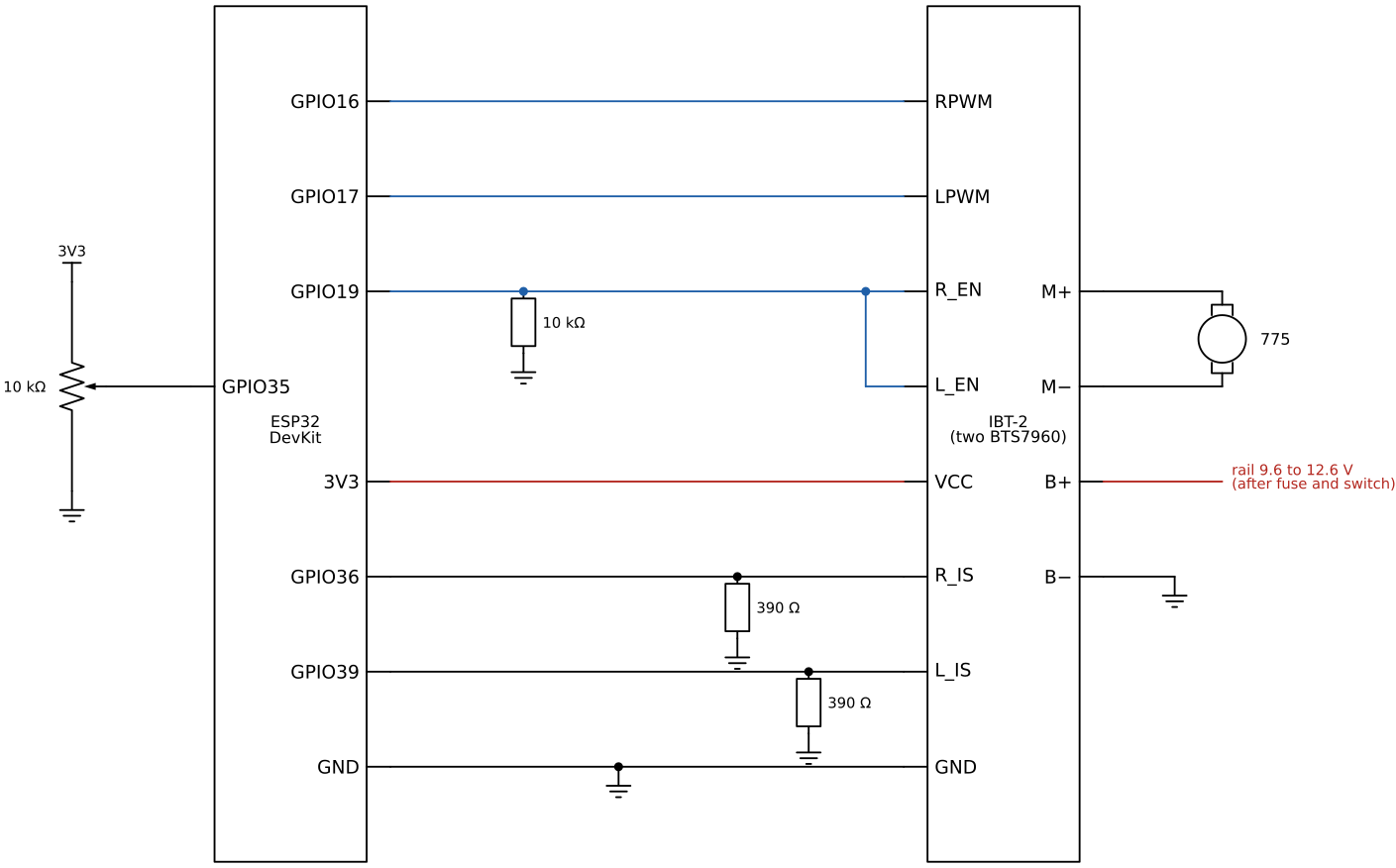
Every wire from the ESP32 to the module carries 3.3 V logic. The potentiometer is fed from 3V3, never from 5 V, VIN or the rail. GPIO 35 tolerates at most about 3.6 V, and 12 V on it destroys the ESP32.
Step 3: Wire the power side
Connect the motor to M+ and M\(-\). For the first run, connect B+ and B\(-\) to the lab power supply set to 12 V with its current limit at 3 A; the motor will start slowly against the limit, and a wiring mistake costs nothing. On the car, B+ comes from the rail after the 20 A fuse and the main switch, and B\(-\) goes to the common ground. Use wire of at least 1.5 mm² (AWG 16) for B+, B\(-\), M+ and M\(-\); the thin jumper wires of the logic side melt at the currents of the power side.
Step 4: Create the project
Create a PlatformIO project named motor as in the PlatformIO chapter and replace platformio.ini with:
[env:esp32dev]
platform = espressif32@6.13.0
board = esp32dev
framework = arduino

upload_speed = 921600
monitor_speed = 115200
monitor_echo = yes
monitor_filters = send_on_enter, esp32_exception_decoder

build_flags =
    -D BAUD=${this.monitor_speed}
    ; BTS7960 (IBT-2) pins, car pin map
    -D MOTOR_RPWM_PIN=16
    -D MOTOR_LPWM_PIN=17
    -D MOTOR_EN_PIN=19
    -D MOTOR_IS_R_PIN=36
    -D MOTOR_IS_L_PIN=39
    ; PWM: LEDC channels 4 and 5, 20 kHz, 8 bit
    -D MOTOR_RPWM_CH=4
    -D MOTOR_LPWM_CH=5
    -D MOTOR_PWM_HZ=20000
    -D MOTOR_PWM_BITS=8
    ; soft start: duty may rise by at most this much per second (2.0 = 0 to full in 0.5 s)
    -D MOTOR_RAMP_PER_S=2.0f
    ; current sense: k_ILIS, resistor on the module (measure yours), our resistor
    -D MOTOR_K_ILIS=8500.0f
    -D MOTOR_IS_R_BOARD_OHM=10000.0f
    -D MOTOR_IS_R_EXT_OHM=390.0f
    ; throttle logic
    -D THROTTLE_DEADBAND=0.08f
    -D REVERSE_ARM_MS=300
    ; bench potentiometer
    -D THROTTLE_POT_PIN=35
    -D POT_CENTER=2048
    -D LOOP_MS=20
    -D PRINT_MS=200
Set MOTOR_IS_R_BOARD_OHM to the value measured in Step 1. Create three files in src/: motor_control.h, motor_control.cpp and main.cpp, with the contents listed in The code. Build, then upload with the motor supply switched off.
Step 5: First run, wheels off the ground
Turn the potentiometer to its middle position, open the serial monitor and switch the motor supply on. The monitor prints five lines per second:
pot throttle=+0.01 COAST duty=+0.00 I=0.00 ATurn the potentiometer slowly clockwise. Past the deadband the state changes to FORWARD, the duty rises from zero and the motor starts, usually once the duty passes 0.1 to 0.2. A fast turn of the potentiometer still gives a smooth start, because the code lets the duty rise by at most 2 per second (Soft start). If the wheel turns backwards for the car, swap M+ and M\(-\).
Now test the throttle logic. Turn back through the middle into the other half: the state becomes BRAKE and the motor stops hard. Return to the middle, wait half a second, and turn the other way again: now the state becomes REVERSE and the motor runs backwards. This is the “double tap” of a hobby speed controller.
Type coast and press Enter, then turn the motor shaft by hand: it turns freely. Type brake and turn it again: it resists, more the faster we turn it. Type pot to give control back to the potentiometer.
Step 6: Check the current reading
Run the motor at full forward throttle and compare the current printed by the program with the current shown by the lab power supply or a clamp meter on the B+ wire. They should agree within about 20 to 30 %. Without load the 775 draws so little that the reading lies near the noise of the ESP32 ADC; the comparison becomes meaningful with the wheels on the floor once the car is assembled. When the readings are plausible, change from the power supply to the battery and repeat Step 5, still with the wheels off the ground.
Troubleshooting
The motor does not turn, the state changes correctly
Check that EN reaches the module: GPIO 19 must read 3.3 V with a multimeter when the state is FORWARD. Check VCC on the module header (3.3 V) and the supply on B+. If the motor hums but does not start, the power supply is in current limit; raise the limit or use the battery.
The motor runs at full speed as soon as the supply is switched on
VCC of the module is on 5 V, or EN has no pull-down and floats high while the ESP32 starts. See Logic levels.
The ESP32 restarts when the motor starts
The motor current pulls the supply of the ESP32 down. On the bench, check that the ESP32 does not take its power from the same lab supply as the motor. On the car, check that the ESP32 is fed from the buck converter, and that the ground wires of the module and the ESP32 meet at the battery ground and not through a thin jumper.
The current always reads 0.00 A in FORWARD
The IS wires are swapped or not connected. FORWARD reads R_IS on GPIO 36, REVERSE reads L_IS on GPIO 39.
FAULT appears in the output
The module signals overcurrent, overtemperature or overvoltage (see Current sensing). Switch the supply off and check the motor for a stalled shaft or a short. An overtemperature shutdown is cleared by coast, which pulls EN low.
How It Works
The brushed DC motor
A brushed DC motor turns electric current into torque. The current \(I\) flows through the rotor windings, which lie in the field of permanent magnets, and the force on the windings gives a torque proportional to the current, \[ T = k I, \] where \(k\) is the motor constant. Turning windings in a magnetic field also induce a voltage, the back-EMF, proportional to the speed \(\omega\), and with the same constant \(k\) in SI units. The voltage \(V\) across the motor terminals therefore drives the current through the winding resistance \(R\) against the back-EMF, \[ V = R I + k \omega . \tag{10.14.1}\]
Two cases of 10.14.1 bound everything the motor does. At standstill the back-EMF is zero and the current is limited only by the winding resistance, giving the stall current \(I_s = V/R\) and the largest torque \(k I_s\). Without load the motor speeds up until the back-EMF almost equals \(V\) and only a small current flows, the no-load current that covers friction. Between these two ends the speed falls linearly with the load torque.
The number 775 names a frame size, and 775 motors sold for 12 V differ a lot. A typical listing gives 7000 rpm and 0.8 A without load and a stall current of 36 A at 12 V; other listings give stall currents from 25 A to well over 100 A. Your motor’s values are found by measuring them (Exercise 1). With the listed values, \[ R = \frac{12}{36}~\Omega = 0.33~\Omega, \qquad \omega_0 = 7000 \cdot \frac{2\pi}{60}~\text{rad/s} = 733~\text{rad/s}, \] \[ k = \frac{V - R I_0}{\omega_0} = \frac{12 - 0.33 \cdot 0.8}{733}~\text{V s/rad} = 0.016~\text{V s/rad}, \] and the stall torque is \(k I_s = 0.016 \cdot 36~\text{N m} = 0.58~\text{N m}\), close to the 0.54 N m the same listing states. At the full 12.6 V of the battery the stall current is \(12.6/0.33~\text{A} = 38~\text{A}\). That is twice the rating of the fuse, and the reason the motor must never be held stalled.
The IBT-2 module
One BTS7960 is a half-bridge: a high-side switch from the supply to the output and a low-side switch from the output to ground, with a driver chip that turns one of them on at a time. The datasheet (Infineon, Rev. 1.1, 2004) gives a path resistance of 16 mΩ for the two switches together, a current limitation at typically 43 A, a supply range of 5.5 to 27.5 V, and PWM operation up to 25 kHz.
Two half-bridges with the motor between their outputs make one full H-bridge, and that is the IBT-2: the right BTS7960 is driven by RPWM and R_EN and reports on R_IS, the left one by LPWM, L_EN and L_IS. Each chip has two logic inputs. IN (RPWM or LPWM on the module) selects the switch: high turns the high side on, low turns the low side on. INH (R_EN or L_EN) enables the chip: low turns both switches off and puts the chip to sleep. The chip itself inserts a dead time between turning one switch off and the other on, so the two switches of one half-bridge never conduct together. The shoot-through that a hand-built bridge must avoid in software cannot be commanded from the IBT-2 header.
A 74HC244 buffer lies between the header and the chips, powered from the VCC pin. It is the reason VCC matters.
Logic levels
The BTS7960 inputs alone accept the ESP32 directly. The datasheet guarantees that IN is read as high above 2.0 V and INH above 2.15 V, and as low below 1.1 V, and allows up to 5.3 V on both. The 74HC244 in front of them is the stricter part: a 74HC chip reads a high only above about 70 % of its own supply. With VCC at 5 V it needs about 3.5 V, more than the 3.3 V an ESP32 delivers, and the input is read at random. With VCC at 3.3 V it needs about 2.3 V, which the ESP32 delivers with a clear margin, and its outputs at 3.3 V are well above the 2.15 V the BTS7960 needs. This is why the module VCC comes from the ESP32 3V3 pin, as it did in the VT2026 labs.
During reset and start-up the ESP32 pins are inputs and drive nothing. A floating EN line can be read as high by the buffer, and with RPWM or LPWM also floating the motor could jerk. The 10 kΩ pull-down from GPIO 19 to ground holds EN low, and the bridge in coast, until the program drives the pin.
The four bridge states
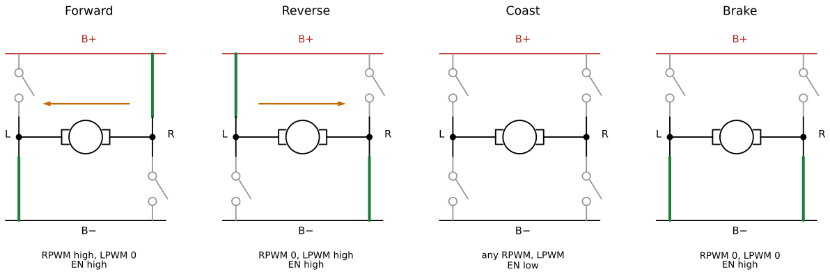
With EN shared, the module has four useful states, shown in Figure 10.14.2. The discrete bridge of the H-bridge chapter has the same four states, set there by four gate signals; here two PWM inputs and one enable line select them.
| EN | RPWM | LPWM | Right half | Left half | Motor |
|---|---|---|---|---|---|
| high | high | low | high side on | low side on | forward, full voltage |
| high | low | high | low side on | high side on | reverse, full voltage |
| high | low | low | low side on | low side on | brake, terminals shorted |
| high | high | high | high side on | high side on | brake through the high sides |
| low | any | any | both off | both off | coast, terminals open |
In forward the current flows from B+ through the right high side, through the motor and the left low side to ground. Reverse uses the other diagonal and reverses the current.
In coast every switch is off. While the motor turns, its back-EMF is smaller than the supply voltage, so no current can flow through the switches or their body diodes, the torque is zero, and the rotor slows down only by friction.
In brake both low sides are on and short the motor terminals. With \(V = 0\) in 10.14.1 the back-EMF drives the current \(I = -k\omega/R\) around the short, and the torque \(kI\) opposes the motion. Braking is strongest at high speed and fades as the motor stops. A full brake from full speed draws almost the stall current: with the 775 above, \(11.7/0.33~\text{A} = 35~\text{A}\), in the range where the low side of the BTS7960 starts limiting its current (33 to 64 A, typically 43 A at 25 °C). That current circulates in the motor and the two low sides; it does not pass the battery or the fuse.
Reversing a spinning motor is harder on the bridge than braking it. The supply and the back-EMF then add, and at full speed the current would be \((12.6 + 11.7)/0.33~\text{A} = 74~\text{A}\), above the current limit of the chip. The throttle logic therefore always brakes before it reverses.
PWM speed control at 20 kHz
Speed is set by pulse width modulation. In forward, RPWM switches between high and low at a fixed frequency \(f\), high for the fraction \(D\) of each period, the duty cycle. While RPWM is high the motor sees the supply voltage \(V_B\); while it is low, the right half-bridge has its low side on and both motor terminals are at ground, which is the brake state. The motor current cannot follow these fast steps because of the winding inductance \(L\), so the motor responds to the average voltage \[ \bar V = D V_B . \] At 11.1 V and \(D = 0.5\), the motor runs as on a 5.6 V supply. Because the off-time connects the motor to ground and does not leave it open, the current keeps flowing through the low side in both halves of the period, and the speed follows the duty cycle almost linearly. The datasheet calls this active freewheeling.
The inductance smooths the current, but not completely. During the on-time the current rises, during the off-time it falls, and the peak-to-peak ripple is about \[ \Delta I = \frac{V_B D (1 - D)}{L f}. \] We have no datasheet value for the inductance of a 775; motors of this size have values in the range of some tens to a few hundred microhenry. With an assumed \(L = 100~\mu\text{H}\), \(V_B = 12~\text{V}\) and \(D = 0.5\), the ripple is \(12 \cdot 0.25/(10^{-4} \cdot 1000)~\text{A} = 30~\text{A}\) at 1 kHz and \(1.5~\text{A}\) at 20 kHz. The large ripple at low frequency heats the motor and the switches without adding torque, and the motor windings vibrate at the PWM frequency and sing. At 20 kHz the ripple is small and the tone lies at the upper end of human hearing. The BTS7960 allows up to 25 kHz, which makes 20 kHz the natural choice. Servos run at 50 Hz for an unrelated reason: their pulse is a position command, not a power signal.
The ESP32 generates the PWM in its LEDC peripheral, which counts a 80 MHz clock. One PWM period of \(2^b\) counts at frequency \(f\) needs \(f \, 2^b \le 80~\text{MHz}\). At 20 kHz and 8 bit, \(20\,000 \cdot 256 = 5.1~\text{MHz}\), well inside the limit; the resolution could be raised to 11 bit (\(41~\text{MHz}\)) before the clock runs out. Eight bits give 256 steps of the duty cycle, finer than we can feel on a throttle. The code uses the core 2 functions ledcSetup(channel, frequency, bits), ledcAttachPin(pin, channel) and ledcWrite(channel, duty); core 3 of the Arduino framework renamed them to ledcAttach and ledcWrite(pin, duty). Channels 4 and 5 are used for the motor because the servo has channel 0. In core 2, ledcWrite with the largest duty (255 at 8 bit) switches the output fully on.
Current sensing
Each BTS7960 has an IS pin that sources a small current proportional to the current through its high-side switch. The ratio is \[ k_{ILIS} = \frac{I_L}{I_{IS}} \approx 8500, \] and a resistor \(R_{IS}\) from IS to ground turns the sense current into a voltage the ESP32 can read, \[ V_{IS} = \frac{I_L}{k_{ILIS}} R_{IS}. \] The ratio is a typical value. The datasheet guarantees it only between 6000 and 11 000 at 30 A, and between 3000 and 14 000 at 5 A, so the reading is good for limits and for comparison, not for measurement better than about 20 to 30 %.
The IS pin has a second job. When the chip detects overcurrent, overtemperature or overvoltage, it switches the IS pin to a fixed fault current \(I_{IS(lim)}\), between 4 and 7 mA (4.5 mA typical), independent of the load. The resistor must be chosen for this case, because the fault current is the largest current the pin ever delivers. The ADC pins of the ESP32 tolerate at most about 3.6 V, and they read up to about 3.1 V. With the 1 kΩ of the VT2026 lab and of the module schematic, a fault gives \[ V_{IS} = 7~\text{mA} \cdot 1000~\Omega = 7~\text{V}, \] and with the 10 kΩ found on many modules the pin rises towards the battery voltage. Both destroy the ADC input. The condition for the pin to stay below 3.3 V at the largest fault current is \[ R_{IS} \le \frac{3.3~\text{V}}{7~\text{mA}} = 471~\Omega . \] The module resistor cannot be removed easily, so we add our own resistor in parallel. With 390 Ω beside a 10 kΩ module resistor, \[ R_{IS} = \frac{10\,000 \cdot 390}{10\,000 + 390}~\Omega = 375~\Omega, \] the fault current gives between \(4 \cdot 0.375 = 1.5~\text{V}\) and \(7 \cdot 0.375 = 2.6~\text{V}\), and normal operation gives \(375/8500~\text{V/A} = 44~\text{mV/A}\), i.e. 0.88 V at 20 A. Beside a 1 kΩ module resistor the same 390 Ω gives 281 Ω, a fault voltage of at most 2.0 V, and 33 mV/A. Either way the pin is safe, and the code computes the parallel value from the two build flags. Normal readings below about 0.1 V lie in the noise of the ADC, which for 375 Ω means below about 2 A.
Because the IS current follows only the high-side switch, the R_IS pin reports in forward and the L_IS pin in reverse, and both read zero in coast and brake. Within one PWM period the high side is on only for the fraction \(D\), so the IS voltage is a pulse train at 20 kHz. The function motorCurrentA() averages 32 ADC readings taken at times unrelated to the PWM, and the average of the pulse train is the average high-side current: the current the bridge draws from the battery. The motor current is larger by the factor \(1/D\), since during the off-time the motor current continues through the low side where the IS pin does not see it.
motorFault() compares both IS voltages with the voltage that 3.5 mA would give, just below the smallest fault current. Normal currents reach that voltage only above \(3.5~\text{mA} \cdot 8500 = 30~\text{A}\), where the chip is already limiting its current and reports a fault anyway. An overtemperature fault stays latched until the enable input has been low for at least 3 µs, which motorCoast() does.
The throttle logic
A throttle is a single number from \(-1\) to \(+1\), and the car must decide whether a negative number means brake or reverse. Hobby speed controllers solve this with the double tap, and throttleUpdate() implements the same rules:
throttleUpdate().
| Throttle | Previous situation | Result |
|---|---|---|
| inside the deadband | any | coast (EN low) |
| positive | stopped at power-on, or last driven forward | forward |
| negative | stopped at power-on, or last driven in reverse | reverse |
| negative | last driven forward | brake |
| negative | braked, then neutral for at least REVERSE_ARM_MS, then negative |
reverse |
| positive | last driven in reverse | brake, then forward after neutral as above |
The rules are symmetric. Driving against the last direction always passes a brake, a release to neutral of at least 300 ms, and a second push. A spinning motor is therefore never reversed under power, which protects the bridge (see The four bridge states), and the driver gets a brake on the same stick motion that would otherwise reverse the car. Neutral coasts, so the car rolls freely when the throttle is released.
Outside the deadband \(d\) the throttle \(t\) is rescaled to a duty cycle that starts at zero at the edge of the deadband, \[ D = \frac{|t| - d}{1 - d}, \] so the motor does not jump to a duty of \(d\) when the throttle leaves neutral. The potentiometer on the bench gives \(t\) from the ADC count \(n\) as \(t = (n - 2048)/2048\).
Soft start
A motor at standstill has no back-EMF, so full throttle from rest draws the stall current at once: \(9.6/0.33~\text{A} = 29~\text{A}\) from a nearly empty battery with the motor of The brushed DC motor. The internal resistance of the battery and the resistance of the wires turn that current into a drop of the rail voltage, and the rail can fall below the 8 V that the XL4015 buck converter needs at its input. The 7.0 V output then sags, and the ESP32 and the servo reset or twitch (Buck converters).
motorDrive() therefore limits how fast the duty magnitude may grow: by at most MOTOR_RAMP_PER_S per second, 2.0 in our build flags, so that full throttle is reached after 0.5 s. During the ramp the motor accelerates and its back-EMF grows with it. At standstill and duty \(D\), the motor current is \(D V_B/R\), and the battery delivers it only for the fraction \(D\) of each period, so the battery current is \(D^2 V_B/R\): at \(D = 0.2\) only 4 % of the stall current. Lowering the duty, braking and coasting take effect at once, since they reduce the current. A change of direction starts the ramp from zero. One side effect: when the throttle is opened on a car that is already rolling, the first small duty cycles act as a mild brake until the duty catches up with the speed.
The code
The project has three source files. motor_control.h declares the interface that the rest of the car uses; it contains no pin numbers.
// motor_control.h: BTS7960 (IBT-2) driver and ESC-like throttle logic.
// Pins and constants come from build_flags in platformio.ini.
#pragma once
#include <Arduino.h>

enum class MotorState : uint8_t { Coast, Forward, Reverse, Brake };

// Set up the two LEDC channels and the enable pin. The bridge starts in coast.
void motorBegin();

// Drive with signed duty u from -1 (full reverse) to +1 (full forward).
// u = 0 holds both motor terminals at ground, which brakes. The applied duty
// rises by at most MOTOR_RAMP_PER_S per second (soft start); it falls at once.
void motorDrive(float u);

// Both half-bridges off (EN low): the motor spins freely.
void motorCoast();

// Both low-side switches on (EN high, both PWM 0): the motor is shorted.
void motorBrake();

// Throttle state machine, throttle from -1 to +1. Call it every loop.
// Positive drives forward, neutral coasts, negative after driving forward
// brakes. Changing direction needs a brake, then neutral for REVERSE_ARM_MS,
// then the new direction (the "double tap" of a hobby ESC).
MotorState throttleUpdate(float throttle, uint32_t now_ms);

MotorState motorState();                  // last state set by any function above
float motorDuty();                        // last signed duty, -1 to +1
const char *motorStateName(MotorState s);

// Average current through the active high-side switch in amperes, i.e. the
// current the bridge draws from the battery. Zero in coast and brake.
float motorCurrentA();

// True if an IS pin carries the fault current I_IS(lim) of the BTS7960.
bool motorFault();
motor_control.cpp implements it. All pins and constants come from build_flags, and the #error guards stop the build with a readable message if one is missing. writeBridge() sets the inactive PWM to zero before the active one rises. The chips would not short the supply even without that order, but a brief moment with both inputs high would brake the motor through the high sides. motorDrive(0) is a brake, since a duty of zero holds both motor terminals at ground; only motorCoast() lets the motor go.
// motor_control.cpp: BTS7960 (IBT-2) driver and ESC-like throttle logic.
#include "motor_control.h"

#if !defined(MOTOR_RPWM_PIN) || !defined(MOTOR_LPWM_PIN) || !defined(MOTOR_EN_PIN) || \
    !defined(MOTOR_RPWM_CH) || !defined(MOTOR_LPWM_CH) || !defined(MOTOR_PWM_HZ) || \
    !defined(MOTOR_PWM_BITS) || !defined(MOTOR_RAMP_PER_S) || \
    !defined(THROTTLE_DEADBAND) || !defined(REVERSE_ARM_MS)
#error "Set the MOTOR_*, THROTTLE_DEADBAND and REVERSE_ARM_MS build_flags in platformio.ini"
#endif

#if !defined(MOTOR_IS_R_PIN) || !defined(MOTOR_IS_L_PIN) || !defined(MOTOR_K_ILIS) || \
    !defined(MOTOR_IS_R_BOARD_OHM) || !defined(MOTOR_IS_R_EXT_OHM)
#error "Set MOTOR_IS_R_PIN, MOTOR_IS_L_PIN, MOTOR_K_ILIS, MOTOR_IS_R_BOARD_OHM and MOTOR_IS_R_EXT_OHM"
#endif

static const uint32_t DUTY_MAX = (1u << MOTOR_PWM_BITS) - 1;

// The IS current flows into the resistor on the module and our resistor in parallel.
static const float IS_R_OHM = MOTOR_IS_R_BOARD_OHM * MOTOR_IS_R_EXT_OHM /
                              (MOTOR_IS_R_BOARD_OHM + MOTOR_IS_R_EXT_OHM);
// I_IS(lim) is at least 4 mA in a fault; flag a fault a little below that.
static const float IS_FAULT_V = 0.0035f * IS_R_OHM;

static MotorState state = MotorState::Coast;
static float duty = 0.0f;
static uint32_t lastMs = 0;  // last motor command, for the soft start

static void writeBridge(bool enable, uint32_t rpwm, uint32_t lpwm) {
  // Turn the inactive side down before the active side goes up.
  if (rpwm == 0) ledcWrite(MOTOR_RPWM_CH, 0);
  if (lpwm == 0) ledcWrite(MOTOR_LPWM_CH, 0);
  if (rpwm > 0) ledcWrite(MOTOR_RPWM_CH, rpwm);
  if (lpwm > 0) ledcWrite(MOTOR_LPWM_CH, lpwm);
  digitalWrite(MOTOR_EN_PIN, enable ? HIGH : LOW);
}

void motorBegin() {
  pinMode(MOTOR_EN_PIN, OUTPUT);
  digitalWrite(MOTOR_EN_PIN, LOW);  // coast while we set up
  ledcSetup(MOTOR_RPWM_CH, MOTOR_PWM_HZ, MOTOR_PWM_BITS);
  ledcSetup(MOTOR_LPWM_CH, MOTOR_PWM_HZ, MOTOR_PWM_BITS);
  ledcAttachPin(MOTOR_RPWM_PIN, MOTOR_RPWM_CH);
  ledcAttachPin(MOTOR_LPWM_PIN, MOTOR_LPWM_CH);
  motorCoast();
}

void motorDrive(float u) {
  u = constrain(u, -1.0f, 1.0f);

  // Soft start: the duty magnitude rises by at most MOTOR_RAMP_PER_S per second.
  // Lowering it is immediate. The time step is capped so that a long pause
  // between calls does not allow a jump. Coast and brake restart the clock, so
  // the first step from rest is one loop period.
  uint32_t now = millis();
  float dt = min(now - lastMs, (uint32_t)100) / 1000.0f;
  lastMs = now;
  float cur = (state == MotorState::Forward || state == MotorState::Reverse) ? duty : 0.0f;
  if (cur * u < 0) cur = 0.0f;  // a change of direction starts from zero
  const float step = MOTOR_RAMP_PER_S * dt;
  if (fabsf(u) > fabsf(cur) + step) u = cur + (u > 0 ? step : -step);

  uint32_t counts = (uint32_t)(fabsf(u) * DUTY_MAX + 0.5f);
  if (u > 0) {
    writeBridge(true, counts, 0);
    state = MotorState::Forward;
  } else if (u < 0) {
    writeBridge(true, 0, counts);
    state = MotorState::Reverse;
  } else {
    writeBridge(true, 0, 0);
    state = MotorState::Brake;
  }
  duty = u;
}

void motorCoast() {
  writeBridge(false, 0, 0);
  state = MotorState::Coast;
  duty = 0.0f;
  lastMs = millis();
}

void motorBrake() {
  writeBridge(true, 0, 0);
  state = MotorState::Brake;
  duty = 0.0f;
  lastMs = millis();
}

MotorState throttleUpdate(float throttle, uint32_t now_ms) {
  static int8_t lastDir = 0;            // +1 forward, -1 reverse, 0 not driven yet
  static bool brakedSinceDrive = false;
  static uint32_t neutralSince = 0;

  throttle = constrain(throttle, -1.0f, 1.0f);
  const float db = THROTTLE_DEADBAND;

  if (fabsf(throttle) <= db) {
    if (state != MotorState::Coast) neutralSince = now_ms;
    motorCoast();
    return state;
  }

  const int8_t want = throttle > 0 ? 1 : -1;
  // Same direction as last time (or the first drive): drive.
  // Opposite direction: only after a brake and REVERSE_ARM_MS of neutral.
  bool armed = state == MotorState::Coast && brakedSinceDrive &&
               now_ms - neutralSince >= REVERSE_ARM_MS;
  bool mayDrive = lastDir == 0 || want == lastDir || armed;

  if (mayDrive) {
    const float u = (fabsf(throttle) - db) / (1.0f - db);  // 0 at the deadband edge
    motorDrive(want * u);
    lastDir = want;
    brakedSinceDrive = false;
  } else {
    motorBrake();
    brakedSinceDrive = true;
  }
  return state;
}

MotorState motorState() { return state; }
float motorDuty() { return duty; }

const char *motorStateName(MotorState s) {
  switch (s) {
    case MotorState::Coast:   return "COAST";
    case MotorState::Forward: return "FORWARD";
    case MotorState::Reverse: return "REVERSE";
    case MotorState::Brake:   return "BRAKE";
  }
  return "?";
}

// Mean IS voltage in volts. The IS output is pulsed at the PWM frequency,
// so we average many samples taken at unrelated times.
static float isVolts(uint8_t pin) {
  const int n = 32;
  uint32_t sum_mV = 0;
  for (int i = 0; i < n; i++) sum_mV += analogReadMilliVolts(pin);
  return sum_mV / (1000.0f * n);
}

float motorCurrentA() {
  uint8_t pin;
  if (state == MotorState::Forward) pin = MOTOR_IS_R_PIN;
  else if (state == MotorState::Reverse) pin = MOTOR_IS_L_PIN;
  else return 0.0f;  // no high-side switch carries current
  return isVolts(pin) / IS_R_OHM * MOTOR_K_ILIS;
}

bool motorFault() {
  return analogReadMilliVolts(MOTOR_IS_R_PIN) > 1000.0f * IS_FAULT_V ||
         analogReadMilliVolts(MOTOR_IS_L_PIN) > 1000.0f * IS_FAULT_V;
}
main.cpp is the bench program. It reads the potentiometer, passes the throttle to throttleUpdate(), prints the state five times per second, and accepts the commands coast, brake and pot from the serial monitor.
#include <Arduino.h>
#include "motor_control.h"

// THROTTLE_POT_PIN, POT_CENTER, LOOP_MS, PRINT_MS and BAUD come from build_flags
#if !defined(THROTTLE_POT_PIN) || !defined(POT_CENTER) || !defined(LOOP_MS) || \
    !defined(PRINT_MS) || !defined(BAUD)
#error "Set THROTTLE_POT_PIN, POT_CENTER, LOOP_MS, PRINT_MS and BAUD in platformio.ini"
#endif

enum class Mode { Pot, Coast, Brake };
static Mode mode = Mode::Pot;

static void readCommand() {
  if (!Serial.available()) return;
  String cmd = Serial.readStringUntil('\n');
  cmd.trim();
  if (cmd == "coast")      mode = Mode::Coast;
  else if (cmd == "brake") mode = Mode::Brake;
  else if (cmd == "pot")   mode = Mode::Pot;
  else Serial.println("commands: coast, brake, pot");
}

void setup() {
  Serial.begin(BAUD);
  motorBegin();
  Serial.println("BTS7960 bench test. Pot centre = neutral. Commands: coast, brake, pot");
}

void loop() {
  static uint32_t lastPrint = 0;
  readCommand();

  // Pot centre is neutral; the ends are full forward and full reverse.
  float throttle = (analogRead(THROTTLE_POT_PIN) - POT_CENTER) / (float)POT_CENTER;
  throttle = constrain(throttle, -1.0f, 1.0f);

  if (mode == Mode::Pot)        throttleUpdate(throttle, millis());
  else if (mode == Mode::Coast) motorCoast();
  else                          motorBrake();

  if (millis() - lastPrint >= PRINT_MS) {
    lastPrint = millis();
    Serial.printf("%-4s throttle=%+.2f  %-7s duty=%+.2f  I=%.2f A%s\n",
                  mode == Mode::Pot ? "pot" : "cmd", throttle,
                  motorStateName(motorState()), motorDuty(), motorCurrentA(),
                  motorFault() ? "  FAULT" : "");
  }
  delay(LOOP_MS);
}
The car project uses motor_control.h and motor_control.cpp unchanged. It sets the same build flags in its own platformio.ini, calls motorBegin() once, and calls throttleUpdate() with the throttle from the remote control in place of the potentiometer.
Exercises
Exercise 1: The motor constants. Hold the motor shaft locked in a vice (never by hand), and apply 1.0 V from the lab power supply with the current limit at 5 A. Read the current and compute the winding resistance \(R\). Then run the motor without load from 12 V, measure the no-load current with the power supply and the speed with a phone tachometer app or the AS5600 sensor, and compute \(k\) from 10.14.1. What stall current and stall torque do your values predict at 12.6 V, and what current does a full brake from full speed draw?
Exercise 2: Choosing the sense resistor. A module has 1 kΩ from each IS pin to ground. Which standard resistor in parallel keeps the pin below 3.0 V at the largest fault current of 7 mA? What is the sensitivity in mV/A, and what voltage does the fault threshold of the code (3.5 mA) correspond to? Change MOTOR_IS_R_BOARD_OHM and MOTOR_IS_R_EXT_OHM accordingly and check that the printed current still agrees with the power supply.
Exercise 3: Ripple in a simulation. In Falstad, build the motor as a 0.33 Ω resistor in series with a 100 µH inductor, connected between the output of a square-wave source (0 to 12 V, duty cycle 0.5) and ground. The source at 0 V plays the low-side switch during the off-time. Plot the inductor current at 1 kHz and at 20 kHz and compare the peak-to-peak ripple with the formula in PWM speed control.
Exercise 4: Trace the throttle logic. Starting at power-on in coast, the throttle takes the values \(+0.6\) for 2 s, \(0\) for 0.1 s, \(-0.5\) for 1 s, \(0\) for 0.5 s, \(-0.5\) for 1 s, and \(+0.5\). Write down the state after each step using Table 10.14.3, then confirm it with the potentiometer and the serial monitor. What changes if the second neutral lasts only 0.2 s?