9.5 Bevel gears
The main shaft of the RC car runs along the car and the wheels turn about axles across it, so at each axle the drive has to turn through a right angle. As in every car whose drive shaft runs along the body, a pair of bevel gearssv. koniska kugghjul does it: a small pinion on the shaft meshes with a large ring gear on the differential, and inside the differential four more bevel gears share the drive between the two wheels. The chapter on gear transmissions introduced the bevel gear pair with its cone angles and virtual number of teeth, and the differential with its speeds and torques. Here we take the bevel gear itself apart.
We start from the pitch cones, for any angle between the shafts, and size the face width. The back cone and Tredgold’s approximation then turn each bevel gear into a spur gear, which gives the undercut limit and its cure, the long-addendum pinion. After the kinds of bevel gears (straight, Zerol, spiral and hypoid) come the forces on the teeth and what they do to the bearings, including the axial force of a spiral bevel gear that changes direction with the hand of the spiral and the direction of rotation. The last parts are about mounting a pair so that the two cones meet, the gears inside the differential of the RC car, and how a straight bevel gear is modelled in CAD from the parametric spur gear.
Pitch cones and the shaft angle
Two spur gears roll on each other along their pitch cylinders. Two shafts that meet at a point \(O\) need surfaces that touch along a line through \(O\) and roll on each other without slipping, and those are two cones with their common apex at \(O\), the pitch conessv. delningskoner of Figure 9.5.3. The pinion’s cone makes the angle \(\delta_1\) with its axis and the gear’s the angle \(\delta_2\) with its own, and the cones touch along the line \(OP\). The angle between the shafts is
\[ \Sigma = \delta_1 + \delta_2 \tag{9.5.1}\]
Figure 9.5.2 cuts the final drive of Figure 9.5.1 by the plane through both axes. The section is the drawing we work with in the rest of the chapter, and the video ends on the pair of Figure 9.5.3.
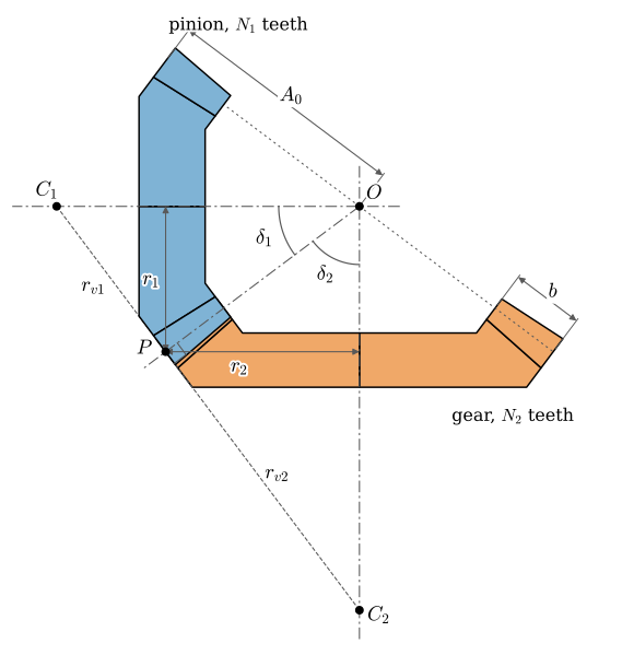
A point of the line \(OP\) at the distance \(\rho\) from the apex lies at the radius \(\rho\sin\delta_1\) from the pinion’s axis and \(\rho\sin\delta_2\) from the gear’s. Rolling without slipping means that the two cones have the same speed there, \(\omega_1\rho\sin\delta_1 = \omega_2\rho\sin\delta_2\), and \(\rho\) cancels, so every point of the line gives the same ratio. The pitch diameters are measured at the back of the teeth, the heel, where the cone distance is \(A_0\), and as for spur gears they are \(d = mN\) with the module \(m\) of the heel. At the heel \(d_1 = 2A_0\sin\delta_1\) and \(d_2 = 2A_0\sin\delta_2\), so
\[ \frac{\omega_1}{\omega_2} = \frac{\sin\delta_2}{\sin\delta_1} = \frac{N_2}{N_1} \tag{9.5.2}\]
The tooth counts fix the ratio, and with 9.5.1 they also fix the cone angles. Writing \(\delta_2 = \Sigma - \delta_1\) and expanding the sine, \(\sin\Sigma\cos\delta_1 - \cos\Sigma\sin\delta_1 = (N_2/N_1)\sin\delta_1\), and dividing by \(\cos\delta_1\) gives
\[ \tan\delta_1 = \frac{\sin\Sigma}{N_2/N_1 + \cos\Sigma}, \qquad \tan\delta_2 = \frac{\sin\Sigma}{N_1/N_2 + \cos\Sigma} \tag{9.5.3}\]
the second by exchanging the gears. For \(\Sigma = 90°\) this is 9.4.7, \(\tan\delta_1 = N_1/N_2\). Bevel gears are made for other shaft angles too [1]; a gear with \(\delta_2 = 90°\) has a flat pitch cone, a crown gear, and is the bevel counterpart of the rack. The cone distance follows from either gear,
\[ A_0 = \frac{d_1}{2\sin\delta_1} = \frac{d_2}{2\sin\delta_2} \tag{9.5.4}\]
which for \(\Sigma = 90°\) is \(A_0 = \tfrac{m}{2}\sqrt{N_1^2 + N_2^2}\), since then \(\sin\delta_1 = N_1/\sqrt{N_1^2 + N_2^2}\).
The face width
Everything on a bevel gear scales with the distance from the apex. At the cone distance \(\rho\) the pitch radius, the module and the tooth itself are \(\rho/A_0\) of their size at the heel, so the teeth taper towards the toe, the front end of the face. The forces are taken at the middle of the face width \(b\), at the mean cone distance \(A_m = A_0 - b/2\), where the pitch radius is
\[ r_m = \frac{A_m}{A_0}\,r = r - \frac{b}{2}\sin\delta \tag{9.5.5}\]
The taper limits how wide the face can usefully be. A tooth is a cantilever whose size grows with \(\rho\), and if the two gears turn as rigid bodies about their axes, the flanks are pressed together by an amount proportional to \(\rho\) as well. According to Section 15-2 of [1], the load across the face is therefore larger at the heel than at the toe. Let the load per unit face width grow in proportion to \(\rho\), \(w = w_0\rho/A_0\) with \(w_0\) at the heel, and the torque it carries about the axis of a gear with the cone angle \(\delta\) is
\[ T = \int_{A_0 - b}^{A_0} w\,\rho\sin\delta\,\mathrm{d}\rho = \frac{w_0\sin\delta}{3A_0}\left(A_0^3 - (A_0 - b)^3\right) \tag{9.5.6}\]
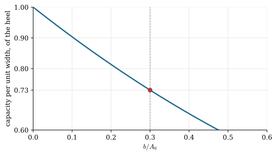
Each added millimetre at the toe carries less than the one before it, because it lies nearer the apex both in load and in moment arm. Compared with a face that carried the heel load \(w_0\) at the heel radius over its whole width, the face of 9.5.6 works at the fraction \(\left(1 - (1 - b/A_0)^3\right)/(3b/A_0)\), which Figure 9.5.4 plots. Hence the rule, from Section 15-5 of [1], that the face width be
\[ b \le \min\left(0.3A_0,\ 10m\right) \tag{9.5.7}\]
The transmissions chapter used a third of the cone distance, the same rule in a rounder number. At \(b = 0.3A_0\) the toe is 70 % of the heel, and the face works at 73 % of the heel’s capacity per millimetre.
Code
beta_b = np.linspace(1e-3, 0.6, 400)                 # b/A_0
use = (1 - (1 - beta_b)**3)/(3*beta_b)               # @eq-bv-capacity over w_0 A_0 b sin(delta)
fig, ax = plt.subplots(figsize=(6.4, 3.4))
ax.plot(beta_b, use, color=BLUE, lw=2)
ax.axvline(0.3, color=GREY, lw=0.8, ls='--')
ax.plot(0.3, (1 - 0.7**3)/0.9, 'o', color=RED)
ax.set_xlim(0, 0.6)
ax.set_ylim(0.6, 1.0)
ax.set_xticks([0, 0.1, 0.2, 0.3, 0.4, 0.5, 0.6])
ax.set_yticks([0.6, 0.73, 0.8, 0.9, 1.0])
ax.set_xlabel('$b/A_0$')
ax.set_ylabel('capacity per unit width, of the heel')
ax.grid(alpha=0.3)
for s in ('top', 'right'):
    ax.spines[s].set_visible(False)
plt.show()The back cone and Tredgold’s approximation
The tooth of a bevel gear has no flat cross-section that holds its true shape. All its points at the cone distance \(A_0\) lie on a sphere about the apex, and the exact profile, the one that keeps the ratio constant, is drawn on that sphere: a spherical involute [2]. A sphere cannot be rolled out flat, but near the pitch circle it can be replaced by the cone that touches it there. This is the back cone of Figure 9.5.3: its generators run from the pitch point \(P\) at right angles to \(OP\), and it meets the gear’s axis at \(C_1\). The triangle \(OPC_1\) has its right angle at \(P\), and the angle at \(C_1\) between \(C_1P\) and the axis equals \(\delta_1\), because both sides are turned by a right angle from \(OP\) and the axis. The pitch radius \(r_1\) is the distance from \(P\) to the axis, so the back-cone radius is
\[ r_{v1} = \frac{r_1}{\cos\delta_1} \tag{9.5.8}\]
A cone can be rolled out flat. Unrolled, the back cone becomes a sector of a circle of radius \(r_{v1}\), and its edge, of length \(2\pi r_1\), carries the \(N_1\) teeth of the pinion at their own pitch \(\pi m\) (Figure 9.5.5). The sector spans the angle \(2\pi r_1/r_{v1} = 2\pi\cos\delta_1\). Completed to a full circle, it is a spur gear of the radius \(r_{v1}\) and the same module, with the virtual number of teeth \(N_{v1} = 2r_{v1}/m = N_1/\cos\delta_1\), 9.4.8. This is Tredgold’s approximation: the teeth of a bevel gear, seen on its back cone, are the teeth of this virtual spur gear [1], and two bevel gears in mesh behave at their heels like the spur pair of radii \(r_{v1}\) and \(r_{v2}\). The approximation is close because the back cone touches the sphere along the whole pitch circle and the teeth are short compared with \(A_0\).
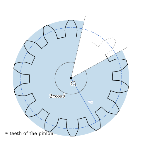
Everything known about spur gears now carries over through \(N_v\): the tooth form, the contact ratio, the Lewis form factor and the undercut limit. The virtual gear of a pinion always has more teeth than the pinion, and that of a large gear far more, since \(\cos\delta_2\) is small; a crown gear has \(N_v = \infty\) and its virtual gear is a rack.
Undercut
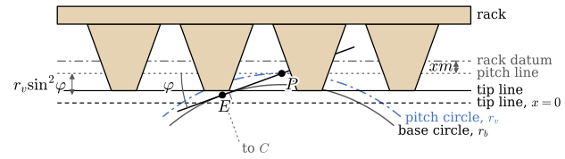
A rack generates a spur gear by rolling its pitch line, the datum of the rack, on the gear’s pitch circle. The straight flank of the rack ends at its tip line, the addendum \(m\) below the datum, and it cuts a true involute only as long as its contact with the gear stays on the line of action between the pitch point \(P\) and the point \(E\) where the line of action touches the base circle (Figure 9.5.6). \(E\) is the foot of the perpendicular from the gear’s centre onto the line of action, at the distance \(r\sin\varphi\) from \(P\) along the line and therefore at the depth \(r\sin^2\varphi\) below the pitch line. A rack whose tip line reaches deeper than \(E\) cuts into the flank below the base circle: this is undercutsv. underskärning. A profile shift \(x\) moves the rack out by \(xm\), so the tip line lies at the depth \((1 - x)m\), and the condition for no undercut is \((1 - x)m \le r\sin^2\varphi\). With \(r = mN/2\) for a spur gear and \(r_v = mN_v/2\) for the virtual gear of a bevel gear,
\[ N_v = \frac{N}{\cos\delta} \ge \frac{2(1 - x)}{\sin^2\varphi} \tag{9.5.9}\]
For \(x = 0\) and \(\varphi = 20°\) the right side is the familiar 17.1 of the spur gear chapter. A bevel pinion gets away with fewer real teeth than a spur gear, by the factor \(\cos\delta_1\), and a pinion that still falls short is given a positive shift. In bevel gears the shift takes the form of unequal addenda: the pinion’s addendum grows by \(xm\) and the gear’s shrinks by the same amount, so the working depth stays \(2m\) and the gears still mesh at the same cone distance.
Example 1: The final drive of the RC car
The final drive of the RC car is a straight bevel pair with shafts at \(\Sigma = 90°\) (Figure 9.5.7). We could not find the tooth counts of the DKS-Pro differential, so we assume a pinion of \(N_1 = 12\) teeth and a ring gear of \(N_2 = 40\), module \(m = 1.5\) mm at the heel and \(\varphi = 20°\), the same 12 and 40 as in Example 4 of the transmissions chapter. Find the cone angles, the cone distance, the widest useful face, the mean pitch radii for a face of \(b = 9\) mm, and the virtual numbers of teeth. Will the pinion be undercut?
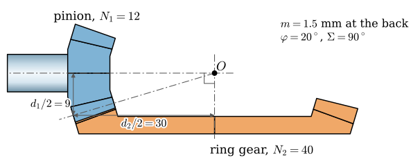
With \(u = N_2/N_1\) the ratio, 9.5.3, 9.5.4, 9.5.7, 9.5.5 and 9.4.8 give, in order,
\[ \begin{aligned} \tan\delta_1 &= \frac{N_1}{N_2}, \qquad \delta_2 = 90° - \delta_1, \qquad A_0 = \frac{m}{2}\sqrt{N_1^2 + N_2^2}\\ b_\text{max} &= \min(0.3A_0,\ 10m), \qquad r_{mi} = \frac{mN_i}{2} - \frac{b}{2}\sin\delta_i, \qquad N_{vi} = \frac{N_i}{\cos\delta_i} \end{aligned} \]
and 9.5.9 with \(x = 0\) gives the limit \(N_v \ge 2/\sin^2\varphi\).
Code
N1, N2, m = 12, 40, 1.5                    # assumed teeth and module of the final drive
b = 9.0                                    # face width [mm]
d1 = np.arctan(N1/N2)                      # pinion cone angle
d2 = np.pi/2 - d1
A0 = m/2*np.hypot(N1, N2)                  # cone distance [mm]
b_max = min(0.3*A0, 10*m)
rm1 = m*N1/2 - b/2*np.sin(d1)              # mean pitch radii [mm], @eq-bv-rm
rm2 = m*N2/2 - b/2*np.sin(d2)
Nv1, Nv2 = N1/np.cos(d1), N2/np.cos(d2)
Nv_min = 2/np.sin(phi)**2
# both gears must reach the same apex: the cone distance from either pitch radius
A0_check = (m*N1/2/np.sin(d1), m*N2/2/np.sin(d2))
The cones, the face and the virtual gears come out as
\[ \begin{aligned}\delta_1 &=16.7^\circ,\quad \delta_2 =73.3^\circ,\quad A_0 =31.32~\text{mm},\quad b_\text{max} =9.396~\text{mm}\\r_{m1} &=7.707~\text{mm},\quad r_{m2} =25.69~\text{mm}\\N_{v1} &=12.53,\quad N_{v2} =139.2,\quad 2/\sin^2\varphi =17.1\end{aligned} \]
As a check, the cone distance computed from the pinion, \(r_1/\sin\delta_1\), and from the ring gear, \(r_2/\sin\delta_2\), agree:
\[ \frac{r_1}{\sin\delta_1} =31.321~\text{mm},\quad \frac{r_2}{\sin\delta_2} =31.321~\text{mm} \]
The face may be 9.4 mm wide, and 9 mm stays inside the limit, with the toe at \((A_0 - b)/A_0 = 71\) % of the heel. The pinion’s mean pitch radius, 7.71 mm, is the moment arm of the tooth force in Example 3. The pinion acts like a spur gear of 12.5 teeth, well below the 17.1 that a \(20°\) involute needs. A cut pinion of this size would be undercut, and a printed one modelled with the full involute would interfere with the ring gear’s tips at the root, the problem the spur gear chapter notes for its model below 18 teeth. The ring gear acts like a spur gear of 139 teeth, nearly a rack.
Example 2: A long-addendum pinion
Give the pinion of Example 1 a long addendum, the gear the matching short one, with the addenda that Table 13-3 of [1] gives for straight bevel gears. Does the pinion then escape undercut (Figure 9.5.6), and how thick are its teeth at the tip?
For a pair with \(\Sigma = 90°\) and the ratio \(u = N_2/N_1\), the table gives the working depth \(2m\) and the gear’s addendum \(a_2 = m\left(0.54 + 0.46/u^2\right)\), written in the module (\(m = 1/P\) for the table’s diametral pitch \(P\)). The pinion takes the rest, \(a_1 = 2m - a_2\), so its shift is
\[ x = \frac{a_1}{m} - 1 = 0.46\left(1 - \frac{1}{u^2}\right) \tag{9.5.10}\]
zero for a pair of equal gears and growing towards 0.46 for large ratios. The undercut check is 9.5.9. For the tip, the tooth thickness at any radius \(r\) follows from the thickness at the pitch circle by 9.2.6 of the spur gear chapter, applied to the virtual pinion of radius \(r_v\); the shift widens the tooth at the pitch circle to \(t_p = m(\pi/2 + 2x\tan\varphi)\) as the spur gear chapter shows, and the tip radius is \(r_a = r_v + (1 + x)m\):
\[ t_a = 2r_a\left(\frac{t_p}{2r_v} + \operatorname{inv}\varphi - \operatorname{inv}\varphi_a\right), \qquad \cos\varphi_a = \frac{r_v\cos\varphi}{r_a} \tag{9.5.11}\]
Code
inv = lambda a: np.tan(a) - a              # involute function, @eq-inv
u = N2/N1
x = 0.46*(1 - 1/u**2)                      # @eq-bv-shift
a1, a2 = (1 + x)*m, (1 - x)*m              # addenda of pinion and gear [mm]
Nv_min_x = 2*(1 - x)/np.sin(phi)**2        # @eq-bv-undercut with the shift


def tip_thickness(Nv, x):
    """@eq-bv-tip on the virtual gear of Nv teeth with the shift x [mm]."""
    rv = m*Nv/2
    ra = rv + (1 + x)*m
    phi_a = np.arccos(rv*np.cos(phi)/ra)
    tp = m*(np.pi/2 + 2*x*np.tan(phi))
    return 2*ra*(tp/(2*rv) + inv(phi) - inv(phi_a))


ta0, ta = tip_thickness(Nv1, 0.0), tip_thickness(Nv1, x)
The shift, the addenda, the new undercut limit and the tip thickness without and with the shift are
\[ \begin{aligned}x &=0.419,\quad a_1 =2.13~\text{mm},\quad a_2 =0.872~\text{mm}\\N_{v1} &=12.5\ \ge\ \frac{2(1 - x)}{\sin^2\varphi} =9.94\\t_a &=0.942~\text{mm}~(x = 0),\quad t_a =0.548~\text{mm}\end{aligned} \]
With \(x = 0.42\) the limit drops from 17.1 to 9.9 virtual teeth, and the pinion’s 12.5 clear it: no undercut. The price is at the tip. The long addendum reaches out where the involute flanks of a small gear converge, and the tip narrows from 0.94 mm to 0.55 mm, \(0.37m\). A common rule of thumb asks for a tip of at least about \(0.25m\), so the pinion passes, but for a printed pinion 0.55 mm is barely more than one extrusion width. This is one reason why Table 13-3 of [1] asks for at least 13 pinion teeth even against a large gear, while 9.5.9 alone would allow fewer, as Figure 9.5.8 shows.
Code
uu = np.linspace(1, 6, 300)
cos_d1 = uu/np.sqrt(1 + uu**2)                         # cos(delta_1) for Sigma = 90
xx = 0.46*(1 - 1/uu**2)
fig, ax = plt.subplots(figsize=(6.6, 3.6))
ax.plot(uu, 2/np.sin(phi)**2*cos_d1, color=GREY, lw=2, label='undercut, $x = 0$')
ax.plot(uu, 2*(1 - xx)/np.sin(phi)**2*cos_d1, color=BLUE, lw=2, label='undercut, long addendum')
table = np.array([(16, 16), (15, 17), (14, 20), (13, 30)])  # Shigley Table 13-3: pinion, gear
ax.plot(table[:, 1]/table[:, 0], table[:, 0], 's', color=RED, label='Table 13-3 of Shigley',
        clip_on=False, zorder=5)
ax.plot(u, N1, 'o', color='black')
ax.annotate('Example 1', (u, N1), xytext=(u + 0.25, N1 + 1.2), fontsize=10)
ax.set_xlim(1, 6)
ax.set_ylim(0, 18)
ax.set_xticks([1, 2, 3, 4, 5, 6])
ax.set_yticks([0, 5, 10, 15, 18])
ax.set_xlabel('ratio $u = N_2/N_1$')
ax.set_ylabel('fewest pinion teeth $N_1$')
ax.grid(alpha=0.3)
ax.legend(frameon=False, loc='lower left', fontsize=9)
for s in ('top', 'right'):
    ax.spines[s].set_visible(False)
plt.show()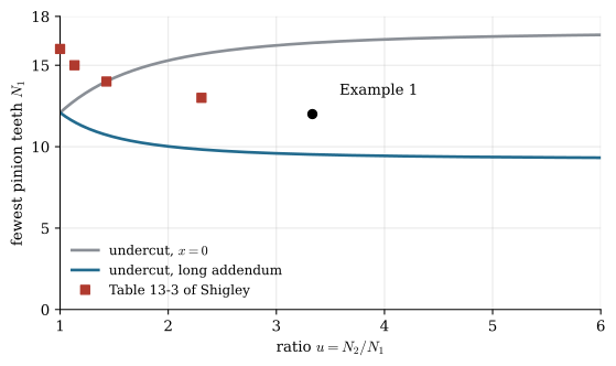
Straight, Zerol, spiral and hypoid gears
The straight bevel gear of Figure 9.5.1 has teeth along the generators of its cone, and a tooth comes into contact along its whole length at once, like a spur gear’s. It is the cheapest bevel gear and the one to print, and Section 15-1 of [1] recommends it for pitch-line speeds up to about 5 m/s where noise does not matter. Above that the knock of each tooth entering the mesh makes it loud.
The spiral bevel gearsv. konisk växel med spiralkugg curves its teeth along the face, as the lower pair of Figure 9.5.1 shows, and is to the straight bevel gear what the helical gear is to the spur gear. The spiral angle \(\psi\) is the angle between the tooth and the pitch cone’s generator at the middle of the face. A tooth enters the mesh at one end and the contact sweeps along it, more teeth share the load, and the pair runs quietly at high speed. The two gears of a pair have opposite hands. The curved tooth also changes the forces: it adds an axial component whose direction depends on the hand and on the direction of rotation, which the next section works out.
The Zerol gear is a spiral bevel gear with the spiral angle zero at the middle of the face. Its teeth are curved, so they are cut on the same machines as spiral bevel gears and are crowned along the face like them, but they act on the bearings like straight teeth, with the same moderate axial force. The same section of [1] designs Zerol gears as straight bevel gears, and they often replace them.
The hypoid gearsv. hypoidväxel moves the pinion’s axis off the gear’s, so the shafts cross without meeting. The pitch surfaces are then hyperboloids, and the teeth slide along each other as well as rolling, as in a worm drive [1]. The offset buys two things in a car: the drive shaft sits lower than the axle, which lowers the floor, and the pinion, for a given gear, is larger and stronger than the pinion of a spiral bevel pair. The sliding costs efficiency and heats the oil, and hypoid gears need gear oils with extreme pressure additives. With a larger offset the pinion turns into a tapered worm.
Forces at the mean radius
The load on a tooth is spread over the face and grows towards the heel (9.5.5). According to Section 13-15 of [1], the usual practice is to let the whole force act at the middle of the face, at the mean pitch radius \(r_m\) of 9.5.5, which the true resultant lies a little outside of. A torque \(T_1\) on the pinion then gives the tangential force
\[ F_t = \frac{T_1}{r_{m1}} \tag{9.5.12}\]
The force between the teeth of a straight bevel pair acts in the plane normal to the tooth, which runs along the generator. In that plane it is tilted from the tangent by the pressure angle \(\varphi\), as for a spur gear (9.4.12), so besides \(F_t\) it has the part \(F_t\tan\varphi\) normal to the pitch cone. On the pinion that part points into the pinion, towards its axis. Let \(\bm{a}\) be the unit vector along the pinion’s axis away from the apex, and \(\bm{e}_r\) the unit vector from the axis out to the mean point \(G\) (Figure 9.5.9). The generator through \(G\) runs along \(\bm{g} = \cos\delta_1\,\bm{a} + \sin\delta_1\,\bm{e}_r\), and the cone’s outward normal at \(G\) is \(\bm{n} = -\sin\delta_1\,\bm{a} + \cos\delta_1\,\bm{e}_r\). The force on the pinion in the plane through its axis is \(-F_t\tan\varphi\,\bm{n}\), and its components along the axis and along \(\bm{e}_r\) are
\[ F_r = F_t\tan\varphi\cos\delta_1, \qquad F_a = F_t\tan\varphi\sin\delta_1 \tag{9.5.13}\]
the radial force \(F_r\) towards the axis and the axial force \(F_a\) along \(\bm{a}\), away from the apex. Both push the pinion out of the mesh. On the gear, 9.5.13 holds with \(\delta_2\). For \(\Sigma = 90°\) we have \(\sin\delta_1 = \cos\delta_2\), so the pinion’s axial force equals the gear’s radial force and the other way round: they are the same force, seen from the two shafts.
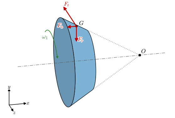
A short SymPy check of the decomposition: the force \(-F_t\bm{e}_t - F_t\tan\varphi\,\bm{n}\) on the pinion, with \(\bm{e}_t\) the direction in which \(G\) moves, has the components 9.5.13 along \(-\bm{e}_r\) and \(\bm{a}\).
Code
Ft_s, ph_s, de_s = sp.symbols('F_t varphi delta', positive=True)
aa, er, et = sp.Matrix([1, 0, 0]), sp.Matrix([0, 1, 0]), sp.Matrix([0, 0, 1])
nn = -sp.sin(de_s)*aa + sp.cos(de_s)*er                       # outward normal of the pitch cone
W = -Ft_s*et - Ft_s*sp.tan(ph_s)*nn                           # gear on pinion, at G
F_r_s, F_a_s = sp.simplify(-W.dot(er)), sp.simplify(W.dot(aa))
\[ F_r =F_{t} \cos{\left(\delta \right)} \tan{\left(\varphi \right)},\qquad F_a =F_{t} \sin{\left(\delta \right)} \tan{\left(\varphi \right)} \]
The three components load the pinion’s bearings. \(F_t\) and \(F_r\) act at the radius \(r_m\) off the axis and \(F_a\) at the radius \(r_m\) too, so \(F_a\) also tilts the shaft with the moment \(F_a r_m\). One bearing has to take \(F_a\) axially, and since both gears are pushed away from the apex, that bearing must hold each gear towards the other. A pinion is often overhung, carried on two bearings behind it like the pinion of Figure 9.5.12, and the bearing next to the gear then carries more than the tooth force itself, as Example 3 shows. A straddle-mounted gear has a bearing on each side, deflects less, and keeps its contact in the middle of the face; the AGMA rating in Section 15-3 of [1] rewards it with a smaller load-distribution factor.
The axial force of a spiral bevel gear
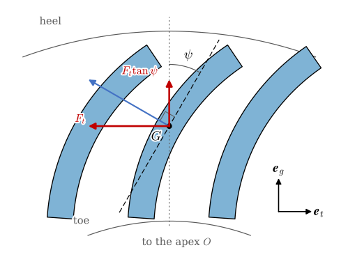
A spiral tooth crosses the generator at the angle \(\psi\). Figure 9.5.10 looks at the pitch cone near \(G\) from outside, with \(\bm{g}\) the generator away from the apex and \(\bm{e}_t\) the direction in which \(G\) moves. The tooth runs along \(\bm\tau = \cos\psi\,\bm{g} + \sin\psi\,\bm{e}_t\), so that its outer end leads. The force on the flank is normal to the tooth, and its part in the pitch plane must be normal to \(\bm\tau\) while its component along \(\bm{e}_t\) is \(-F_t\). That part is \(-F_t\bm{e}_t + F_t\tan\psi\,\bm{g}\), since \((-\bm{e}_t + \tan\psi\,\bm{g})\cdot\bm\tau = -\sin\psi + \tan\psi\cos\psi = 0\). The part normal to the pitch cone is now \(F_t\tan\varphi_n/\cos\psi\), with \(\varphi_n\) the pressure angle in the plane normal to the tooth, because the force normal to the tooth is \(F_t/\cos\psi\). Adding the new term \(F_t\tan\psi\,\bm{g}\), with \(\bm{g} = \cos\delta\,\bm{a} + \sin\delta\,\bm{e}_r\), to the axial and radial parts gives
\[ \begin{aligned} F_a &= \frac{F_t}{\cos\psi}\left(\tan\varphi_n\sin\delta + s\sin\psi\cos\delta\right)\\ F_r &= \frac{F_t}{\cos\psi}\left(\tan\varphi_n\cos\delta - s\sin\psi\sin\delta\right) \end{aligned} \tag{9.5.14}\]
with \(s = +1\) for the case drawn. With \(\psi = 0\) they reduce to 9.5.13. Turning the pinion the other way reverses \(\bm{e}_t\), and a spiral of the other hand reverses \(\bm\tau\); either one flips the sign of the term in \(\sin\psi\), so \(s = -1\). The rule that follows is visible in Figure 9.5.10. A driving pinion whose teeth, followed from the toe to the heel, lean in the direction it turns is pushed away from the apex, out of the mesh (\(s = +1\)); one whose teeth lean the other way is pulled towards the apex, into the mesh, as soon as \(\sin\psi\cos\delta_1 > \tan\varphi_n\sin\delta_1\).
Code
phi_n = np.radians(20)
psi = np.linspace(0, np.radians(45), 300)
Fa_ratio = {s: (np.tan(phi_n)*np.sin(d1) + s*np.sin(psi)*np.cos(d1))/np.cos(psi) for s in (1, -1)}
psi_rev = np.arcsin(np.tan(phi_n)*np.tan(d1))      # where F_a changes sign for s = -1
For the pinion of Example 1, \(\delta_1 = 16.7°\), Figure 9.5.11 plots the axial force over the spiral angle. With \(s = -1\) it changes sign where \(\sin\psi = \tan\varphi_n\tan\delta_1\), at
\[ \psi =6.27^\circ \]
Code
fig, ax = plt.subplots(figsize=(6.6, 3.6))
ax.plot(np.degrees(psi), Fa_ratio[1], color=BLUE, lw=2, label='$s = +1$: pushed out of mesh')
ax.plot(np.degrees(psi), Fa_ratio[-1], color=RED, lw=2, label='$s = -1$: pulled into mesh')
ax.axhline(0, color='black', lw=0.8)
ax.plot(np.degrees(psi_rev), 0, 'o', color=RED)
ax.set_xlim(0, 45)
ax.set_ylim(-1.0, 1.2)
ax.set_xticks([0, round(np.degrees(psi_rev), 1), 15, 30, 35, 45])
ax.set_yticks([-1.0, -0.5, 0, 0.5, 1.0, 1.2])
ax.xaxis.set_major_formatter(plt.FormatStrFormatter('%g'))
ax.yaxis.set_major_formatter(plt.FormatStrFormatter('%g'))
ax.set_xlabel(r'spiral angle $\psi$ [°]')
ax.set_ylabel('$F_a/F_t$ on the pinion')
ax.grid(alpha=0.3)
ax.legend(frameon=False, loc='upper left', fontsize=9)
for s_ in ('top', 'right'):
    ax.spines[s_].set_visible(False)
plt.show()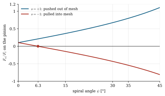
At the common spiral angle of \(35°\) the pinion is pushed out of the mesh with \(0.80F_t\) in one direction of rotation and pulled in with \(0.54F_t\) in the other, more than five times the axial force of the straight pinion either way. A pinion pulled into the mesh takes up its backlash, and if its bearing yields it can wedge the teeth. Designers therefore choose the hand so that the pinion is pushed out in the main direction of drive, and the bearing that locates the pinion axially is made to take the force in both directions, since a car also drives in reverse and the wheels drive the pinion when the car coasts.
Example 3: The bearings of the pinion
The straight pinion of Example 1 sits on the end of its shaft, overhung, with bearing \(A\) at \(c = 15\) mm behind the mean point \(G\) and bearing \(B\) another \(s = 25\) mm behind (Figure 9.5.12). Bearing \(A\) takes the axial force. The shaft carries \(T_1 = 0.5\) N·m, the torque at the pinion in Example 4 of the transmissions chapter. Find the forces on the bearings.
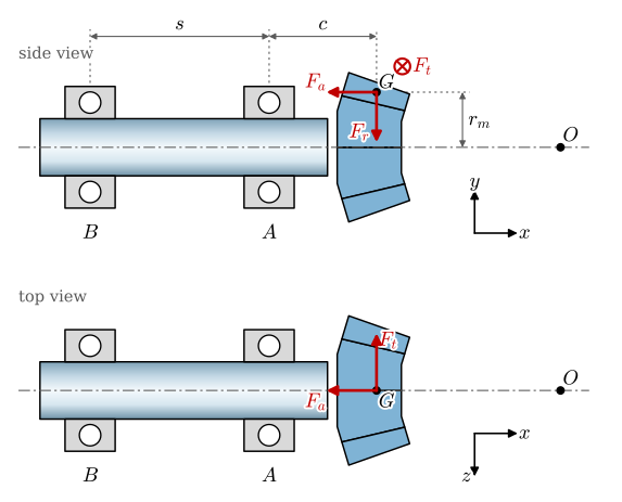
We take \(x\) along the shaft towards the apex, \(y\) from the axis up to \(G\) and \(z = \bm{e}_x\times\bm{e}_y\), out of the side view, so that \(G\) moves along \(+z\). With the forces of 9.5.12 and 9.5.13, the force of the ring gear on the pinion at \(G\) is \(\bm{W} = [-F_a,\ -F_r,\ -F_t]^\mathsf{T}\). Bearing \(A\) carries \(\bm{R}_A = [A_x,\ A_y,\ A_z]^\mathsf{T}\) and bearing \(B\) only radial force, \(\bm{R}_B = [0,\ B_y,\ B_z]^\mathsf{T}\), and the coupling at the shaft’s far end delivers the torque \(T_1\bm{e}_x\). From \(A\), the mean point lies at \(\bm{r}_{AG} = [c,\ r_{m1},\ 0]^\mathsf{T}\) and \(B\) at \(\bm{r}_{AB} = [-s,\ 0,\ 0]^\mathsf{T}\). Equilibrium of the shaft and pinion is
\[ \begin{aligned} \bm{W} + \bm{R}_A + \bm{R}_B &= \bm{0}\\ \bm{r}_{AG}\times\bm{W} + \bm{r}_{AB}\times\bm{R}_B + T_1\bm{e}_x &= \bm{0} \end{aligned} \]
six equations for \(A_x\), \(A_y\), \(A_z\), \(B_y\), \(B_z\) and, as a check, \(T_1\) itself, which the \(x\) component of the moment equation returns as \(r_{m1}F_t\).
Code
T1 = 0.5                                     # pinion torque [N m]
c, s_AB = 15.0, 25.0                         # bearing distances [mm]
Ft = T1/(rm1*1e-3)                           # @eq-bv-Ft [N]
Fr, Fa = Ft*np.tan(phi)*np.cos(d1), Ft*np.tan(phi)*np.sin(d1)

Ax, Ay, Az, By, Bz, Tx = sp.symbols('A_x A_y A_z B_y B_z T_x', real=True)
W = sp.Matrix([-Fa, -Fr, -Ft])
RA, RB = sp.Matrix([Ax, Ay, Az]), sp.Matrix([0, By, Bz])
rAG, rAB = sp.Matrix([c, rm1, 0])*1e-3, sp.Matrix([-s_AB, 0, 0])*1e-3      # [m]
eqs = list(W + RA + RB) + list(rAG.cross(W) + rAB.cross(RB) + sp.Matrix([Tx, 0, 0]))
sol = sp.solve(eqs, [Ax, Ay, Az, By, Bz, Tx])
RA_n, RB_n = np.hypot(float(sol[Ay]), float(sol[Az])), np.hypot(float(sol[By]), float(sol[Bz]))
The tooth forces are
\[ F_t =64.9~\text{N},\quad F_r =22.6~\text{N},\quad F_a =6.79~\text{N} \]
and the bearing forces, with the radial loads \(\sqrt{A_y^2 + A_z^2}\) and \(\sqrt{B_y^2 + B_z^2}\),
\[ \begin{aligned}A_x &=6.79~\text{N},\quad A_y =34.1~\text{N},\quad A_z =104.0~\text{N},\quad R_A =109.0~\text{N}\\B_y &=-11.5~\text{N},\quad B_z =-38.9~\text{N},\quad R_B =40.6~\text{N}\\ T_x &=0.5~\text{N m}\end{aligned} \]
The moment equation returns the input torque, 0.5 N·m, as it must. Bearing \(A\) carries a radial load of 109 N, 1.7 times the tangential force, because the shaft is a lever: \(B\) pulls the shaft the other way (\(B_z < 0\)) and \(A\) is the fulcrum. Figure 9.5.13 shows how both loads grow with the overhang \(c\). Shortening the overhang, or spreading the bearings, helps more than a larger bearing; putting a bearing in front of the pinion helps most, Problem 4.
Code
cc = np.linspace(5, 40, 200)
# from the moment equation about A: B_z = -c F_t/s, B_y = (r_m F_a - c F_r)/s
Bz_c, By_c = -cc*Ft/s_AB, (rm1*Fa - cc*Fr)/s_AB
RA_c, RB_c = np.hypot(Fr - By_c, Ft - Bz_c), np.hypot(By_c, Bz_c)
fig, ax = plt.subplots(figsize=(6.6, 3.6))
ax.plot(cc, RA_c, color=RED, lw=2, label='bearing $A$')
ax.plot(cc, RB_c, color=BLUE, lw=2, label='bearing $B$')
ax.axhline(np.hypot(Ft, Fr), color=GREY, lw=1, ls='--', label='tooth force $\\sqrt{F_t^2 + F_r^2}$')
ax.plot([c, c], [RB_n, RA_n], 'o', color='black')
ax.set_xlim(5, 40)
ax.set_ylim(0, 200)
ax.set_xticks([5, 10, 15, 20, 25, 30, 35, 40])
ax.set_yticks([0, 50, 100, 150, 200])
ax.set_xlabel('overhang $c$ [mm]')
ax.set_ylabel('radial bearing load [N]')
ax.grid(alpha=0.3)
ax.legend(frameon=False, loc='upper left', fontsize=9)
for s_ in ('top', 'right'):
    ax.spines[s_].set_visible(False)
plt.show()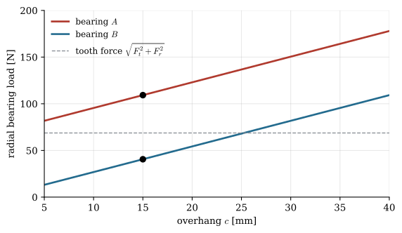
Mounting a pair
The theory of 9.5.1 assumes that the two pitch cones share their apex. A spur pair whose centre distance is a little off still meshes with the right ratio and only gains backlash. A bevel pair whose apexes do not meet has its cones crossing each other, and the teeth then touch at one end of the face only, at the toe or at the heel, where the load of the whole face gathers on a few millimetres.
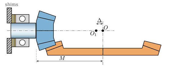
Each gear is therefore located along its own axis by its mounting distance \(M\), the distance from the other gear’s axis to a reference face on the gear, usually its back face (Figure 9.5.14). Shims between a bearing and the housing set it: a stack of thin rings whose total thickness is chosen at assembly. Moving a gear along its axis by \(\Delta\) moves its pitch cone off the other’s. The pinion’s pitch cone, moved along its axis, leaves the common generator by the component of the move normal to it, \(e = \Delta\sin\delta_1\); for the gear, \(e = \Delta\sin\delta_2\). In the plane of the back cone this is a spur pair moved apart by \(e\). Moving a flank inclined at \(\varphi\) outwards by \(e\) shifts it along the pitch line by \(e\tan\varphi\), and both flanks of a tooth space do so, so the circular backlashsv. flankspel grows by
\[ \Delta j = 2\Delta\sin\delta\tan\varphi \tag{9.5.15}\]
for a gear moved by \(\Delta\) away from the apex. The large gear, with \(\sin\delta_2\) close to one, sets the backlash; the pinion, with its small \(\delta_1\), hardly changes it but moves the contact along the face. The usual procedure follows from this: the pinion is shimmed to its mounting distance so that the contact lies in the middle of the face, and then the ring gear is shimmed along its axis until the backlash is right.
The contact must also stay put under load. The shafts bend and the housing yields, and the teeth move relative to each other along the face. Bevel gears are therefore crowned: the teeth are made slightly thinner towards both ends, so that the contact is a patch in the middle of the face that moves but does not run off an end when the mounting deflects, as Section 15-3 of [1] notes for most bevel gears. In a printed differential the carrier and the housing are the mounting, and a tenth of a millimetre of print error in the bore that locates the pinion moves its apex as much as a shim would.
The differential of the RC car
The gears inside the differential are bevel gears too: two side gears, one on each half-shaft, and two spiders on the cross pin of the carrier, all four with their apexes at the centre of the carrier, so that the side gear and spider of each mesh form a \(90°\) pair. Straight teeth are the rule here, since the spiders only turn when the wheels turn at different speeds and then slowly. The transmissions chapter found how the speeds and torques divide. The forces on the teeth show what holds the gears in place, and that is the subject of the last example.
Example 4: Spiders and side gears
The differential of Example 4 of the transmissions chapter has side gears of \(N_2 = 16\) teeth and spiders of \(N_1 = 10\) (Figure 9.5.15). We assume module \(m = 1.25\) mm and the face width \(b = 3.5\) mm. The ring gear delivers the carrier torque \(T_c = 1.67\) N·m, which by 9.4.11 is split into \(T_c/2\) per half-shaft. Find the cone angles and the virtual numbers of teeth, the tangential force at each mesh, the force on the cross pin from each spider, and the axial forces that push the spiders and the side gears against the carrier.
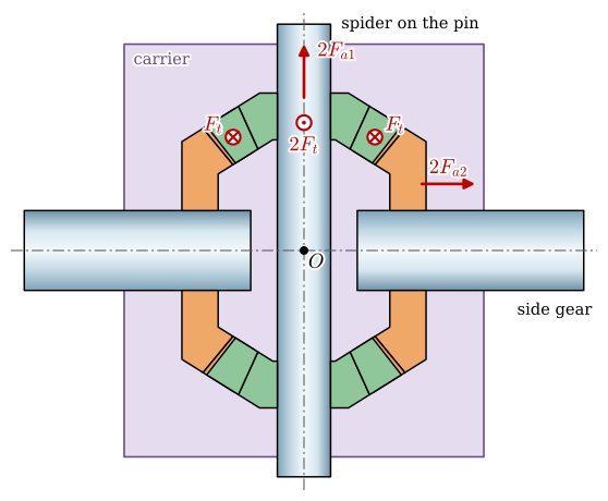
Each side gear meshes with both spiders, so its torque \(T_c/2\) is shared by two meshes at the mean radius \(r_{m2}\) of the side gear:
\[ F_t = \frac{T_c/2}{2r_{m2}} \]
Both side gears hold the spider back with \(F_t\) on the same side (Figure 9.5.15), so the pin pushes the spider with \(2F_t\), as on the idler of Example 1 of the transmissions chapter. The radial forces of 9.5.13 on the spider come from opposite sides and cancel, and so do those on each side gear from the two spiders. The axial forces add up: each spider is pushed out along its pin by \(2F_{a1} = 2F_t\tan\varphi\sin\delta_1\), and each side gear out along its half-shaft by \(2F_{a2} = 2F_t\tan\varphi\sin\delta_2\), both against the carrier.
Code
Nsp, Nsd, m_d, b_d = 10, 16, 1.25, 3.5      # spider, side gear (assumed)
T_c = 0.5*40/12                             # carrier torque from the transmissions example [N m]
dsp = np.arctan(Nsp/Nsd)                    # spider cone angle, Sigma = 90
dsd = np.pi/2 - dsp
A0_d = m_d/2*np.hypot(Nsp, Nsd)
rm_sd = m_d*Nsd/2 - b_d/2*np.sin(dsd)       # mean radius of the side gear [mm]
Ft_d = (T_c/2)/(2*rm_sd*1e-3)               # per mesh [N]
F_pin = 2*Ft_d
Fa1_2, Fa2_2 = 2*Ft_d*np.tan(phi)*np.sin(dsp), 2*Ft_d*np.tan(phi)*np.sin(dsd)
Nv_sp, Nv_sd = Nsp/np.cos(dsp), Nsd/np.cos(dsd)
# check: the two pins drive the carrier's torque through four meshes at r_m of the side gears
T_check = 4*Ft_d*rm_sd*1e-3
The geometry and the forces are
\[ \begin{aligned}\delta_1 &=32.0^\circ,\quad \delta_2 =58.0^\circ,\quad A_0 =11.8~\text{mm},\quad 0.3A_0 =3.54~\text{mm}\\N_{v1} &=11.8,\quad N_{v2} =30.2,\quad r_{m2} =8.52~\text{mm}\\F_t &=48.9~\text{N},\quad 2F_t =97.9~\text{N},\quad 2F_{a1} =18.9~\text{N},\quad 2F_{a2} =30.2~\text{N}\end{aligned} \]
As a check, the four meshes, each with \(F_t\) at the radius \(r_{m2}\) from the axle, carry the whole carrier torque back to the half-shafts:
\[ 4F_t r_{m2} =1.667~\text{N m} = T_c \]
The face of 3.5 mm is just under \(0.3A_0 = 3.54\) mm. Each spider presses on its pin with 98 N, twice the tooth force, and the pin carries this in shear at both ends where it sits in the carrier. The side gears are pushed outwards with 30 N each and the spiders with 19 N, so the carrier needs flat thrust faces, or washers, behind the side gears and spherical seats behind the spiders. In a printed carrier these faces wear first, and friction on them is part of what resists the wheels turning at different speeds. The spiders act like spur gears of 11.8 teeth, below the 17.1 of 9.5.9, so they need a long addendum as much as the final drive pinion does (Problem 5).
Modelling a straight bevel gear in CAD
A straight bevel gear can be built from the parametric spur gear with three ideas. The first is that every line on a straight bevel tooth runs to the apex: the flanks, the root and the tip are swept by lines through \(O\). A loft from a tooth profile to a single point, the apex, produces exactly such surfaces, so the tooth space is cut by a loft from its profile at the heel to \(O\) and needs no second profile at the toe. The second is Tredgold’s approximation: the profile at the heel is the tooth space of the virtual spur gear of \(N_v\) teeth (9.4.8), centred at \(C_1\) on the axis, and it is drawn on the plane through the pitch point \(P\) at right angles to the generator \(OP\), the plane that touches the back cone along \(PC_1\). The spur gear model accepts a fractional tooth count, since \(N\) enters its sketch only through the angular pitch, so the profile comes from it with \(N_v\) in place of \(N\). The third is that the circular pattern then needs the real tooth count \(N\), which must be kept as a separate variable.
The sequence is as follows. A revolved blank holds the gear: in the sketch on a plane through the axis, its outline is the tip cone from the toe to the heel, the back cone, the back face and the bore, the cones drawn as lines from the apex at the angles from 9.5.3 with the addendum and dedendum of 9.5.10. A reference plane through \(P\) normal to the line \(OP\) carries the profile of one tooth space of the virtual gear, with its centre at \(C_1\), the point where that plane meets the axis at the distance \(r_v\) of 9.5.8 from \(P\). A cut-loft from this profile to the apex point removes the tooth space, and a circular pattern of \(N\) copies about the axis completes the gear. The loft cuts towards the apex beyond the toe, where the blank has no material, so the face width is set by the blank alone.
Two simplifications remain. The tip and root cones of this model run to the apex, so the clearance between the tip of one gear and the root of the other shrinks towards the toe in proportion to the cone distance; standard straight bevel gears have a uniform clearance instead [1], a difference too small to matter for a printed pair. And the profile lies on a plane that touches the back cone, not on the cone itself. At the distance \(s\) across the plane from \(PC_1\), the cone falls away from the plane by \(s^2/(2A_0)\), since the back cone’s normal at \(P\) points along \(PO\) and its curvature across the generator has the radius \(A_0\). That gap lies along the rays to the apex, so it only scales the profile there, by the fraction \(s^2/(2A_0^2)\). For half a tooth pitch of the pinion of Example 1, \(s = 1.2\) mm and \(A_0 = 31.3\) mm, the profile is scaled by 0.07 %.
Problems
Problem 1: Shafts at 60°. A bevel pair connects shafts that meet at \(\Sigma = 60°\), with \(N_1 = 15\), \(N_2 = 30\) and \(m = 2\) mm. Find the cone angles and the cone distance. Compare the cone angles with those of the same gears at \(90°\), Figure 9.5.16.
Answer: 9.5.3 gives \(\tan\delta_1 = \sin 60°/(2 + \cos 60°) = 0.346\), \(\delta_1 = 19.1°\), \(\delta_2 = 40.9°\), and 9.5.4 \(A_0 = 15/\sin 19.1° = 45.8\) mm. At \(90°\) the angles are \(26.6°\) and \(63.4°\): the smaller shaft angle makes both cones slimmer.
Problem 2: Shims. In the final drive of Example 1, a shim of 0.1 mm is added behind the ring gear, moving it 0.1 mm away from its apex (Figure 9.5.17). How much does the backlash grow? How much would the same shim behind the pinion change it, and what does the pinion shim change instead?
Answer: 9.5.15 gives \(\Delta j = 2 \cdot 0.1 \cdot \sin 73.3° \tan 20° = 0.070\) mm for the ring gear and \(2 \cdot 0.1 \cdot \sin 16.7° \tan 20° = 0.021\) mm for the pinion. The pinion shim mainly moves the pinion’s apex off the ring gear’s, and with it the contact towards the toe or the heel.
Problem 3: Which hand? The pinion of Example 1 is made as a spiral bevel gear with \(\psi = 35°\) and \(\varphi_n = 20°\) and drives with \(F_t = 64.9\) N (Figure 9.5.18). Find the axial force on the pinion for the two directions of rotation. Which way must its teeth lean, followed from the toe to the heel, for the pinion to be pushed out of mesh when the car drives forwards?
Answer: With 9.5.14, \(F_a = 0.80F_t = 52\) N away from the apex with \(s = +1\) and \(-0.54F_t = -35\) N, towards the apex, with \(s = -1\). The teeth must lean in the direction the pinion turns when the car drives forwards, so that their heel leads.
Problem 4: Straddle mounting. The pinion of Example 3 gets a bearing \(B\) 10 mm in front of \(G\), between the pinion and the apex, and bearing \(A\) moves to 10 mm behind \(G\) (compare Figure 9.5.19). Find the radial loads on both bearings.
Answer: With \(\bm{r}_{AB} = [20,\ 0,\ 0]^\mathsf{T}\) mm the moment equation gives \(B_z = cF_t/s = 32.4\) N and \(B_y = (cF_r - r_mF_a)/s = 8.7\) N, and the force equation \(A_y = 13.9\) N, \(A_z = 32.4\) N: \(R_A = 35.3\) N and \(R_B = 33.6\) N, against 109 N and 41 N overhung. In a real final drive the front bearing has to fit inside the ring gear, which is why it is small.
Problem 5: Long-addendum spiders. What shift do the spiders of Example 4 need to escape undercut, and what does 9.5.10 of Table 13-3 give for their ratio (Figure 9.5.20)?
Answer: 9.5.9 with \(N_v = 11.8\) asks for \(x \ge 1 - 11.8\sin^2 20°/2 = 0.31\). 9.5.10 with \(u = 1.6\) gives \(x = 0.46(1 - 1/2.56) = 0.28\), a little short, so the spiders are slightly undercut with the table’s addenda. With 10 spider teeth they are below the 13 that the table allows at any ratio; differentials accept this because the spiders turn slowly and only in corners.
Further reading
Budynas and Nisbett [1] give the terminology and Tredgold’s approximation in Section 13-9, the tooth proportions of straight bevel gears in Table 13-3, the forces in Section 13-15 and the AGMA rating of straight bevel gears in Chapter 15, with the classification of spiral, Zerol, hypoid and spiroid gears in Section 15-1. Litvin and Fuentes [2] derive the exact geometry of straight, spiral bevel and hypoid gears, including the spherical involute. ISO 23509 [3] defines the geometry of all bevel and hypoid gears in the form the gear makers use. The gears inside the differential are treated as a mechanism in the transmissions chapter, and the involute profile that the virtual gear borrows is built in the spur gear chapter.
References
[1]
Budynas RG, Nisbett JK. Shigley’s mechanical engineering design. 10th ed. New York: McGraw-Hill Education; 2014.
[2]
Litvin FL, Fuentes A. Gear geometry and applied theory. 2nd ed. Cambridge: Cambridge University Press; 2004.
[3]
ISO 23509:2016 Bevel and hypoid gear geometry. Geneva, Switzerland: International Organization for Standardization; 2016.