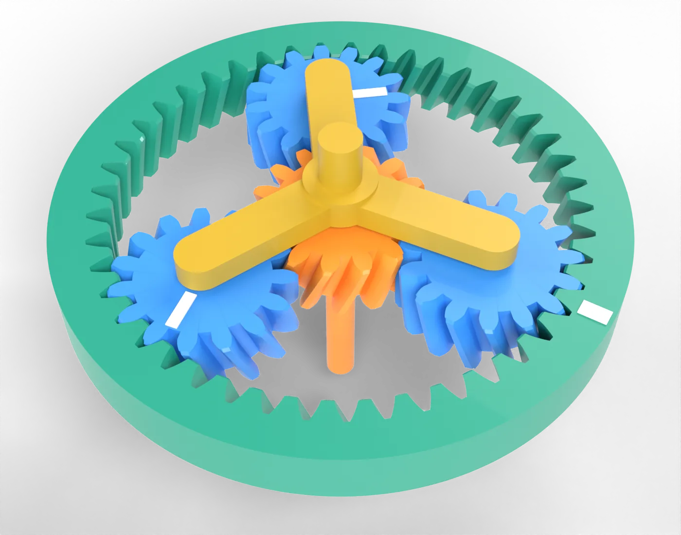
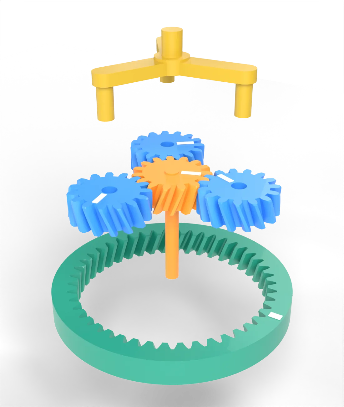
A pair of spur gears reaches a ratio of about six before the pinion gets too small or the wheel too large, and the two shafts stand side by side. A planetary gearsv. planetväxel puts the gears inside one another: a sun gearsv. solhjul in the middle, three or more planetssv. planethjul around it, and a ring gearsv. ringhjul with internal teeth around them all. The planets turn on pins in a carriersv. planethållare, which turns about the same axis as the sun and the ring (Figure 9.6.1). Input and output are coaxial, the load is shared by all the planets, and the gearbox is short and round; it sits behind the motor of a robot joint, in the hub of a bicycle, between the engine and the wheels of every automatic car and in the first stage of a wind turbine’s gearbox.
(a) Assembled, with the yellow carrier on top. The white stripes show how far each gear has turned.
(b) Pulled apart along the axis: the carrier with its three pins, the sun and the planets, and the ring.
Figure 9.6.1: A planetary gear set with an orange sun of 15 teeth, three blue planets of 15 teeth and a teal ring of 45 teeth, helical with module 2, the numbers of the printed gearbox in [1].
The chapter first fixes the geometry, then derives the one equation that gives all the speeds, the Willis equation, and checks it with a velocity diagram. From the forces on a planet follow the torques on the three members. The rules for choosing the numbers of teeth come next, then stages in series and the differential, a planetary gear made of bevel gears. The last part looks at backlash and efficiency, measured on 3D-printed gearboxes. The cycloidal and strain wave drives of the next chapter are planetary gears too, and the Willis equation gives their ratios as well.
Sun, planets, ring and carrier
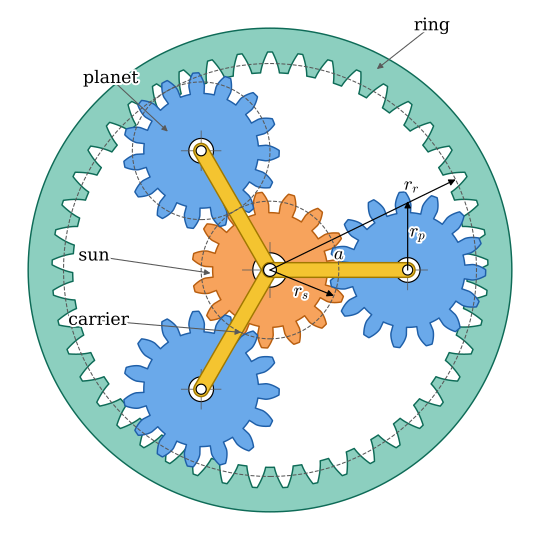
Figure 9.6.2 shows the gear set along its axis. The sun of \(N_s\) teeth meshes with each planet of \(N_p\) teeth, and each planet meshes with the ring of \(N_r\) teeth. All the gears share the module \(m\), so the pitch radii are \(r = mN/2\). The carrier holds the planet centres at the distance \(a = r_s + r_p\) from the axis, and the planets must reach the ring as well, \(a = r_r - r_p\). The two give \(r_r = r_s + 2r_p\), or in teeth
\[
N_r = N_s + 2N_p
\tag{9.6.1}\]
The ring is the largest gear and its teeth fix the size of the gearbox. In Figure 9.6.2, \(15 + 2 \cdot 15 = 45\).
Figure 9.6.2: The gear set of Figure 9.6.1 along the axis. The carrier, drawn as three arms, holds the planet centres at \(a = r_s + r_p\); the dashed lines are the pitch circles of the sun, one planet and the ring.
Four members can move: the sun, the ring, the carrier and the planets. The planets turn on their pins and are never connected to a shaft, so three members are left that can be an input, an output or held still, and each choice gives a different ratio.
Seen from the carrier: the Willis equation
If the carrier stands still, the planetary gear is an ordinary gear train with fixed axes: the sun drives the planets, which drive the ring. The planets are idlers, so the ratio from the sun to the ring is \(-N_r/N_s\), the minus sign because the ring turns the other way. When the carrier turns, we look at the gear set from the carrier, in a frame that turns with it at \(\omega_c\). In that frame every axis stands still again, and every gear turns at its speed relative to the carrier, \(\omega - \omega_c\). The sun drives a planet at an external mesh and the planet drives the ring at an internal mesh, which keeps the sense:
Multiplying the two removes the planet. The ratio between sun and ring seen from the carrier is the ratio of the train with the carrier held, the basic ratiosv. grundutväxling\(i_0\):
This is the Willis equation. According to [2], articles 407 and 408, the revolutions of a wheel in an epicyclic train are those relative to the arm plus those of the arm: 9.6.2 read backwards. It is one equation in three speeds, so two of them must be given, an input and a held member, to find the third. The planets have dropped out, and their number does not matter for the speeds.
Figure 9.6.3 shows the three ways of holding one member, with the held member grey.
Figure 9.6.3: The gear set of Figure 9.6.1 with one member held (grey) in turn. Ring held: the sun drives and the carrier turns once while the sun turns four times. Carrier held: the sun drives and the ring turns backwards, once for three turns of the sun. Sun held: the ring drives and the carrier turns three times for four turns of the ring.
A check: the velocities across a planet
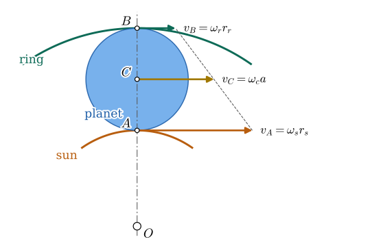
The Willis equation can be found a second way, which also shows what goes on inside the planet. Along the line from the axis through a planet centre (Figure 9.6.4), the planet touches the sun at \(A\) and the ring at \(B\), and the teeth roll there without slipping: the planet’s point \(A\) moves with the sun’s pitch circle at \(v_A = \omega_s r_s\), its point \(B\) with the ring’s at \(v_B = \omega_r r_r\). The planet is rigid, so the velocity across it is linear, and its centre \(C\), halfway between \(A\) and \(B\), moves at the mean of the two. The centre is also a point on the carrier, \(v_C = \omega_c a\):
\[
\omega_c\, a = \frac{\omega_s r_s + \omega_r r_r}{2}
\]
The carrier speed is the mean of the sun and ring speeds weighted by their teeth.
Figure 9.6.4: The velocities along the line through the axis \(O\) and a planet centre \(C\). The planet moves with the sun at \(A\) and with the ring at \(B\), and is rigid, so its velocity is linear between them; \(C\) is a point of the carrier.
9.6.2 and 9.6.3 must be the same equation. SymPy confirms it by solving both for \(\omega_c\):
Holding one member and driving another leaves six combinations. For each, 9.6.2 with the held speed set to zero gives the ratio \(i = \omega_\text{in}/\omega_\text{out}\):
Code
members = {'sun': w_s, 'ring': w_r, 'carrier': w_c}rows = []for held, w_h in members.items():for inp, w_in in members.items():for out, w_out in members.items():iflen({held, inp, out}) <3:continue w_out_sol = sp.solve(willis.subs(w_h, 0), w_out)[0] # output speed for the input i = sp.simplify(w_in/w_out_sol) rows.append((held, inp, out, i, i.subs({N_s: 15, N_r: 45})))table = pd.DataFrame(rows, columns=['held', 'input', 'output', 'i', 'i (15/45)'])
With the gear set of Figure 9.6.1 in the last column:
held
input
output
i
i (15/45)
sun
ring
carrier
\(\frac{N_{r} + N_{s}}{N_{r}}\)
\(\frac{4}{3}\)
sun
carrier
ring
\(\frac{N_{r}}{N_{r} + N_{s}}\)
\(\frac{3}{4}\)
ring
sun
carrier
\(\frac{N_{r} + N_{s}}{N_{s}}\)
\(4\)
ring
carrier
sun
\(\frac{N_{s}}{N_{r} + N_{s}}\)
\(\frac{1}{4}\)
carrier
sun
ring
\(- \frac{N_{r}}{N_{s}}\)
\(-3\)
carrier
ring
sun
\(- \frac{N_{s}}{N_{r}}\)
\(- \frac{1}{3}\)
The largest reduction is the usual one: ring held, sun in, carrier out, \(i = 1 + N_r/N_s\). With the carrier held the gear set is an ordinary train and the ring turns backwards. With the sun held the ratio lies between one and two. The other three rows are the same three driven backwards, as speed increasers. Since \(N_r = N_s + 2N_p\), the ratio \(1 + N_r/N_s\) is at least 3, with planets that shrink to nothing, and in practice it lies between about 3 and 10 in one stage [1]: a larger ratio needs a sun so small that it cannot carry the torque or planets so large that they touch each other.
Example 1: the three cases
The gear set of Figure 9.6.3 is driven at 3000 rpm by a motor. Find the output speed in each of the three cases, and the speed of a planet on its pin, which decides the life of the planet’s bearing.
The output speeds follow from the table above. A planet turns on its pin at its speed relative to the carrier, \(\omega_p - \omega_c\), which the first of the two mesh relations gives:
With the ring held, the carrier turns at a quarter of the motor speed, and the planets turn on their pins at \(-2250\) rpm, three quarters of the motor speed, backwards: the bearing inside a planet runs almost as fast as the motor although the planet stands on the slow member. With the carrier held, the planets turn as fast as the sun, since they have the same number of teeth. With the sun held, the ring drives at 3000 rpm and the planets again turn at \(2250\) rpm on their pins.
Torques and the forces on the teeth
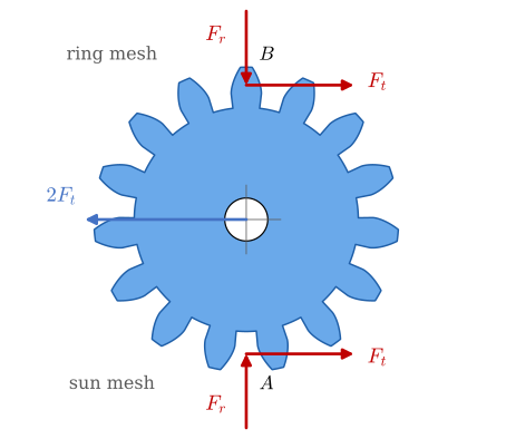
The speeds depend on which member is held; the torques do not. Figure 9.6.5 frees one planet. The sun pushes on it at \(A\) with the tangential force \(F_t\), and its pin turns freely, so the moments about the pin must cancel: the ring pushes at \(B\) with the same \(F_t\), in the same direction, and the pin carries \(2F_t\). The radial parts \(F_r = F_t\tan
20^\circ\) of the two mesh forces point against each other and cancel on the planet.
Figure 9.6.5: One planet freed from the sun, the ring and its pin. The moments about the pin cancel, so both meshes carry the same tangential force \(F_t\), and the pin carries \(2F_t\). The radial forces \(F_r\) cancel.
With \(K\) planets that share the load equally, the sun, the ring and the carrier carry the torques, from the forces on them at their radii,
\[
T_s = K F_t r_s,\qquad T_r = K F_t r_r,\qquad T_c = -2KF_t\,a = -KF_t\,(r_s + r_r)
\]
The three torques add up to zero, as they must for a gear set that does not accelerate, and the carrier carries the sum of the other two. A motor torque \(T_s\) on the sun puts the force
on each mesh. With the ring held, the carrier delivers \((1 + N_r/N_s)T_s = iT_s\), as 9.4.2 requires without losses, and the housing that holds the ring takes \((N_r/N_s)T_s\).
The sun meshes with \(K\) planets at once, so each tooth carries \(1/K\) of what it would carry in a single pair of gears, so for the same module and tooth stress the gears can be a third as wide. With the planets equally spaced the radial forces on the sun cancel, so the sun needs no bearing of its own for them; some gearboxes let it float between the planets, where it finds the position in which they share the load evenly.
Example 2: the forces in a printed gearbox
The 3D-printed gearbox of [1] has two stages, each with \(N_s = 15\), \(N_p = 15\), \(N_r = 45\), three planets and module \(m = 1.5\) mm, driven by a NEMA 17 stepper motor that gives about \(T_m = 0.28\) N·m (Figure 9.6.6). Find the ratio, the tangential force on each mesh in both stages, the force on a planet pin and the torque the housing must hold.
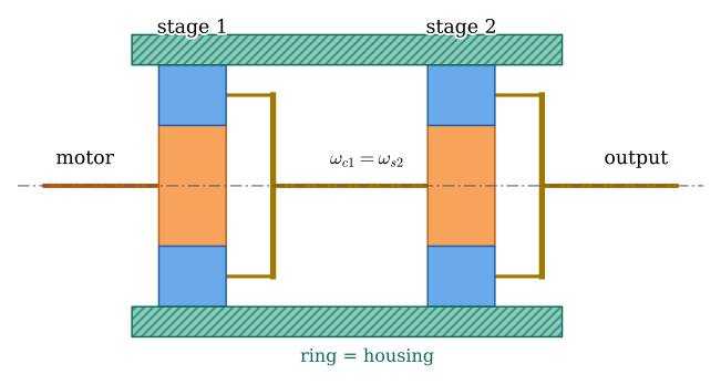
Figure 9.6.6: Two planetary stages in series, cut along the axis. The carrier of the first stage is the sun shaft of the second, and both rings are the housing.
The carrier of stage 1 drives the sun of stage 2, so the ratios multiply, \(i = i_1 i_2\), and the input torque of stage 2 is the output torque of stage 1. 9.6.6 gives the mesh force of each stage, the pin carries \(2F_t\), and the housing holds the two ring torques, \((N_r/N_s)T_s\) per stage.
Code
T_m, m2, K =0.28, 1.5e-3, 3# motor torque [N m], module [m], planetsi_1 =1+ Nr_/Ns_ # each stage, ring heldi_tot = i_1**2T_s1, T_s2 = T_m, i_1*T_m # sun torques of stage 1 and 2F_t1, F_t2 = (2*T/(K*m2*Ns_) for T in (T_s1, T_s2)) # @eq-pg-ftT_housing = (Nr_/Ns_)*(T_s1 + T_s2) # both ring torquesT_out = i_tot*T_m
The first stage is lightly loaded, and the second carries four times as much, since its sun takes the output torque of the first; the second stage decides the strength, which the Lewis estimate of the transmissions chapter checks. The housing holds 4.2 N·m, almost the whole output torque of 4.5 N·m, so the ring of a gearhead is bolted to the machine and never left to the motor’s flange alone.
How many teeth?
9.6.1 ties the three numbers together, and three more rules narrow the choice [1].
Equal spacing. The planets should sit at equal angles \(2\pi/K\), so that the radial forces on the sun cancel and the load is shared. Fit the first planet, then turn the carrier by \(2\pi/K\) with the ring held, to bring that planet to the place of the next one. The sun turns by \(i\cdot 2\pi/K = (1 + N_r/N_s)\,2\pi/K\), or \((N_s + N_r)/K\) of its teeth. The next planet fits only if the sun’s teeth are then where they were, so
\[
\frac{N_s + N_r}{K}\ \text{is a whole number}
\tag{9.6.7}\]
The gear set of Figure 9.6.2 has \((15 + 45)/3 = 20\).
Room for the planets. Two neighbouring planet centres are \(2a\sin(\pi/K)\) apart, and the tips of two planets must not touch, \(2a\sin(\pi/K) > m(N_p + 2)\), or \((N_s + N_p)\sin(\pi/K) > N_p + 2\). Three planets fit almost always; five or six need a large sun.
A hunting tooth. With \(N_s = N_p = 15\), every tooth of the sun meets the same tooth of a planet at every turn, and any flaw in one tooth wears its partner. If the numbers of teeth of two meshing gears have no common factor, a tooth meets every tooth of the other gear before it meets the first one again, and the wear spreads over all of them. Such coprime numbers are called a hunting toothsv. jagande kugg pair.
Example 3: choosing the teeth
Choose the teeth of a stage with three planets and a ratio close to 4, with a ring of at most 60 teeth and no gear under 12 teeth, which meets all four rules: 9.6.1, 9.6.7, room for the planets and coprime sun-planet and planet-ring pairs.
The search runs over the sun and planet teeth; 9.6.1 gives the ring and \(i = 1 +
N_r/N_s\) the ratio.
The six sets closest to a ratio of 4 that pass all the rules:
\(N_s\)
\(N_p\)
\(N_r\)
\(i\)
20
19
58
3.9
19
20
59
4.105
17
16
49
3.882
16
17
50
4.125
14
13
40
3.857
13
14
41
4.154
The 15/15/45 set of Figure 9.6.1 fails only the hunting tooth rule, and it cannot be mended: a ratio of exactly 4 needs \(N_r = 3N_s\), so \(N_p = N_s\), and then sun and planet share every factor. An exact ratio and a hunting tooth exclude each other here. Of the sets that pass, 17/16/49 with \(i = 3.88\) and 16/17/50 with \(i = 4.13\) keep about the size of the 45-tooth ring; 20/19/58 comes closer to 4 with a ring a quarter larger. A designer who needs an exact ratio, for a joint whose angle the software computes from the motor’s steps, keeps 15/15/45 and accepts the uneven wear; one who builds a hoist takes 16/17/50.
Stages in series and the automatic gearbox
One stage gives a ratio of 3 to 10. Stages in series (Figure 9.6.6) multiply their ratios, and two or three stages reach 16 to 500 in a gearhead the diameter of the motor. Each stage loses a few per cent, so the efficiency falls with the number of stages, \(\eta = \eta_1\eta_2\cdots\).
An automatic gearbox uses the six ratios of the table instead. Two or three planetary sets are joined so that their members share shafts, and clutches and brakes decide which member is held and which is driven: each combination of engaged clutches and brakes gives one gear. The chapter on brakes and clutches treats these elements. Holding a member is all it takes to change the ratio, and the gears stay in mesh throughout.
The differential is a planetary gear
The differential of a car has bevel gears, but its kinematics is that of a planetary gear. The case is the carrier, and the two side gears play the sun and the ring: the spider gears between them are the planets. Seen from the case, a spider gear turns one side gear backwards at the speed of the other, so the basic ratio is \(i_0 = -1\).
Example 4: the differential with the Willis equation
Use 9.6.2 with \(i_0 = -1\) to find the speed of the case from the speeds \(\omega_1\) and \(\omega_2\) of the two wheels, and compare with the differential section of the transmissions chapter.
9.6.2 with \(\omega_s = \omega_1\), \(\omega_r = \omega_2\) and \(i_0 = -1\) reads \(\omega_1 - \omega_c = -(\omega_2 - \omega_c)\).
The case turns at the mean of the two wheel speeds, as in the transmissions chapter: in a corner, the outer wheel gains what the inner one loses. With both wheels at the same speed the spider gears stand still on their pins and the differential turns as one block.
Backlash and efficiency of a printed gearbox
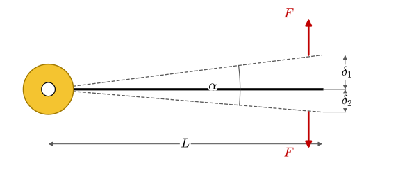
Two numbers describe how good a gearbox is for a robot joint: the backlashsv. glapp, the angle the output can turn while the input is held, and the efficiency. Both depend on how tightly the teeth fit, and they pull in opposite directions. In [1] and [3] the backlash is measured with an arm on the output shaft (Figure 9.6.7): with the motor held, a small force, 1 to 2 % of the gearbox’s torque, pushes the tip of the arm one way and then the other, and the tip moves \(\delta_1 + \delta_2\). The backlash is the angle
Figure 9.6.7: Measuring backlash: with the input held, a small force \(F\) pushes an arm of length \(L\) on the output shaft one way and then the other, and the tip moves \(\delta_1\) and \(\delta_2\).
Example 5: what the printed gearboxes measured
The two-stage gearbox of Example 2 was tested twice. In the first test [1], with plain bushings in the planets, the arm was \(L = 100\) mm, the tip moved 0.3 mm and 0.2 mm under 1.5 N, the motor gave 0.28 N·m and the output held 20 N at 100 mm. In the second test [3], with ball bearings in the planets and \(L = 200\) mm, the tip moved 2.9 mm and 0.75 mm, and the gearbox was printed with three fits of the teeth, from loose to tight, which gave 3.5, 3.1 and 2.9 N·m at the output with a motor of 0.22 N·m. Find the backlash and the efficiency in each case.
Code
def backlash_arcmin(d1, d2, L):return np.degrees(np.arctan((d1 + d2)/L))*60# @eq-pg-backlashalpha_1 = backlash_arcmin(0.3, 0.2, 100)alpha_2 = backlash_arcmin(2.9, 0.75, 200)eta_1 =20*0.100/(16*0.28) # @eq-pg-eta, first testeta_fits = [T/(16*0.22) for T in (3.5, 3.1, 2.9)] # loose, medium, tighteta_stage = np.sqrt(eta_1) # two equal stages
The first gearbox lost more than half the motor torque, about a third in each stage, mostly in the plastic bushings of the planets and the tight teeth. With ball bearings, the loose fit passes by these readings almost all the torque; the video estimates 90 to 95 %, since the motor torque is not known better than that. Its backlash is a full degree, 63 arc minutes by 9.6.8; the video first states 16 arc minutes for this angle of about 1°, a slip, and later uses about 60. Printing the teeth tighter halved the backlash to about 30 arc minutes and cost 17 percentage points of efficiency. A printed gearbox cannot have both; the tighter fit also wore in during a long test and lost part of its advantage [3].
TipIn industry
Planetary gearheads are bought from a catalogue by frame size, ratio and backlash class. The catalogue gives the rated output torque for a stated life, a short-time peak torque, the backlash in arc minutes, the torsional stiffness and the efficiency per stage, and the designer checks the duty cycle of the machine against them with the manufacturer’s service factors. The gear geometry, the number of planets and the hunting-tooth choice are the manufacturer’s business. The same building block, in steel and much larger, is the first stage of a wind turbine gearbox and every stage of a car’s automatic gearbox, where clutches and brakes select which member is held.
Problems
Problem 1: Sun held. In the gear set of Figure 9.6.8 the sun is held and the ring is driven at 1200 rpm by a torque of 10 N·m. Find the carrier speed and torque and the torque on the sun, without losses.
Figure 9.6.8: The gear set of Problem 1, with 15, 15 and 45 teeth, as in Example 1.
Answer:From the table, \(i = 1 + N_s/N_r = 4/3\), so \(n_c = 900\) rpm. 9.6.5 with \(T_r = 10\) N·m gives \(T_s = 10 \cdot 15/45 = 3.33\) N·m and \(T_c = -13.3\) N·m: the carrier delivers 13.3 N·m, and \(13.3 \cdot 900 = 10 \cdot 1200\).
Problem 2: A speed increaser. The same gear set, with the ring held, is driven at the carrier by a hand crank at 60 rpm. How fast does the sun turn, and in which direction?
Figure 9.6.9: The gear set of Problem 2.
Answer:\(\omega_s = (1 + N_r/N_s)\,\omega_c = 4 \cdot 60 = 240\) rpm, in the same direction as the crank.
Problem 3: More planets. Can the 15/15/45 gear set of Figure 9.6.10 carry four, five or six planets instead of three?
Figure 9.6.10: The gear set of Problem 3.
Answer:Equal spacing, 9.6.7: \((15 + 45)/K = 60/K\) is whole for \(K = 4\), 5 and 6. Room: \((15 + 15)\sin(\pi/K) > 17\) gives \(21.2\) for four and \(17.6\) for five, which pass, and \(15.0\) for six, which fails. Four or five planets fit; with five the tips of neighbouring planets clear by only 0.6 module.
Problem 4: Backlash at the end of an arm. A robot arm of 400 mm hangs on a gearbox with 30 arc minutes of backlash. How far can the tip of the arm move with the motor held?
Figure 9.6.11: The measurement of Problem 4.
Answer:\(400\tan(30/60)^\circ = 3.5\) mm: a printed planetary gearbox is a poor choice for the shoulder of an arm that must place parts to a millimetre.
Further reading
Budynas and Nisbett [4] treat planetary trains with the train value in the section on gear trains of Chapter 13, and Willis [2] gives the method of relative revolutions in its original form. The two videos of How To Mechatronics [1,3] show the design, printing, assembly and testing of the gearbox of the examples, and compare it with a cycloidal drive and a belt drive.
How To Mechatronics. Cycloidal vs belt vs planetary: The best 3D printed drive for your next robotic project? 2025. https://www.youtube.com/watch?v=9CDH4NMT_Pc (accessed October 12, 2026).