10.3 First light: an LED on the lab supply
The first experiment is the one Ben Eater starts his series with: an LED connected straight to an adjustable lab supply, and the voltage turned up slowly while we watch the current. It takes ten minutes, and it shows the most important property of the LED, the one that every LED circuit in this book is designed around. Watch the video first.
Ben turns the voltage up without a current limit and destroys his LED at about 2.2 V. We set the current limit of the supply first, so that the supply protects the LED, and we see the same behaviour without losing the part.
What we need
A red 5 mm LED, a breadboard, two jumper wires, the lab supply with its two leads, and the datasheet of the LED. If the kit came without a datasheet, the one for Kingbright’s WP7113SRD1 is typical for a red 5 mm LED and is used for the numbers in this chapter.
Step 1: Find the legs
An LED conducts in one direction only, from the anode (+) to the cathode (−). The anode has the longer leg. The cathode has the shorter leg, and the rim of the plastic body is flattened on the cathode side, which still works after the legs have been cut to the same length. In a schematic the LED is a triangle pointing in the direction of the current, with a bar on the cathode side.
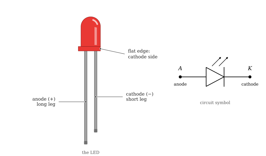
Connected the wrong way round, the LED stays dark and nothing is damaged at the voltages we use. If in doubt, the diode test of the multimeter shows which leg is which (Continuity and diode test).
Step 2: Read the datasheet
Open the LED datasheet and find two tables. Under Absolute maximum ratings the WP7113SRD allows a continuous forward current of 30 mA. Under Electrical characteristics it gives the forward voltage at a test current of 20 mA: 1.85 V typical and 2.5 V maximum.2 These are the numbers on the little card that came with Ben’s LEDs, “1.9 to 2 V at 20 mA”. They tell us where the LED is happy, and they tell us how much current it can take.
Write the prediction in the lab log: the LED should start to glow somewhere below 1.8 V and reach 20 mA near 1.9 V.
Step 3: Set the supply
Follow the routine of The bench power supply: output off, VOLTAGE at zero, current limit at 20 mA. The limit is the rated test current of the LED and well below its 30 mA absolute maximum, so whatever happens next the LED survives.
Step 4: Build
Push the LED into the breadboard with its two legs in two different columns. Run the red lead of the supply to the column of the long leg and the black lead to the column of the short leg, as in Figure 10.3.2.
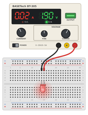
Check the build against the list in Before switching on.
Step 5: Turn up the voltage
Switch the output on and raise the voltage in small steps, 0.1 V at a time to begin with and 0.02 V at a time once the LED starts to glow. At each step write the voltage, the current and the brightness in the log. The current display of the BT-305 counts in steps of 0.01 A, so the current column fills with 0.00, 0.01 and 0.02; a supply with a milliampere display gives finer numbers. The coarse steps and the brightness already tell the story.
| Voltage (V) | Current (A) | LED |
|---|---|---|
| 1.50 | ||
| 1.60 | ||
| 1.70 | ||
| 1.75 | ||
| 1.80 | ||
| 1.85 | ||
| 1.90 | ||
| 1.95 | ||
| 2.00 |
Below about 1.6 V nothing happens: the LED is dark and the current display shows zero. Then the LED begins to glow, and from there on each small step in voltage multiplies the current: within about 0.1 V the display jumps from 0.00 to 0.02. Ben sees the same thing, between 4:00 and 6:00 in the video. At some step the current reaches the 20 mA limit, the C.V. lamp goes out and the C.C. lamp lights. Turn the VOLTAGE knob further: the current stays at 20 mA, the displayed voltage stops rising, and the LED keeps its brightness. The supply has taken over and holds the current at the limit.
What Ben’s LED shows us
Without a current limit, Ben’s supply holds whatever voltage he sets, and the LED takes whatever current that voltage drives through it. From 7:00 in the video, he goes a little above 2 V. The current runs from 20 mA to 300 mA within a quarter of a volt, the LED glows red-hot inside, and then it is dead.
Figure 10.3.3 is the same experiment in the Falstad circuit simulator. It starts at 1.85 V, where the simulated LED carries about 20 mA, the typical values from the datasheet. Drag the Supply voltage slider on the right and watch the current. Between 1.7 V and 2.0 V the current goes from almost nothing to far beyond the 30 mA the LED may carry. The simulated LED is a generic model, so its numbers differ a little from ours and from Ben’s, but the shape is the same.
Here lies the whole difficulty with LEDs. A resistor takes a current proportional to its voltage. The LED takes almost nothing until about 1.7 V and then more current for each hundredth of a volt. The forward voltage also differs from LED to LED (1.85 V typical, up to 2.5 V, says the datasheet) and falls as the LED warms up. Setting the voltage across an LED therefore does not set its current, and a supply that holds a fixed voltage across an LED, like a battery, a USB charger or an ESP32 pin, will sooner or later destroy it. The lab supply saved our LED only because we set its current limit. The next chapter replaces the current limit of the supply by a part that does the same job in any circuit: a resistor.
Exercises
Exercise 1: The curve in numbers
Plot the current against the voltage from your log, by hand or in Python. Mark the datasheet’s typical forward voltage at 20 mA on the plot. Then use the slider in Figure 10.3.3 to find the voltages at which the simulated LED carries 1 mA, 10 mA and 30 mA. How many millivolts separate 10 mA from 30 mA?
Exercise 2: Another colour
Repeat Steps 2 to 5 with a green or blue LED, after finding its datasheet. Compare the voltage at which it reaches 20 mA with the red one. Why does the C.C. lamp tell you that the blue LED has reached its working point, even if you do not know its forward voltage?
Exercise 3: The wrong way round
Turn the LED around and repeat Step 5 up to 3 V. What do the current display and the lamps show? What would you conclude, in a larger circuit, if the supply showed a voltage but no current at all?
Kingbright, WP7113SRD/D T-1 3/4 (5mm) Solid State Lamp, Spec No DSAF2433, Rev V.9A, 2020, page 2, Absolute Maximum Ratings and Electrical / Optical Characteristics; the current against voltage graph is on page 3. kingbrightusa.com↩︎
Kingbright, WP7113SRD/D T-1 3/4 (5mm) Solid State Lamp, Spec No DSAF2433, Rev V.9A, 2020, page 2, Absolute Maximum Ratings and Electrical / Optical Characteristics; the current against voltage graph is on page 3. kingbrightusa.com↩︎