9.17 Sizing welds with SolidWorks Simulation
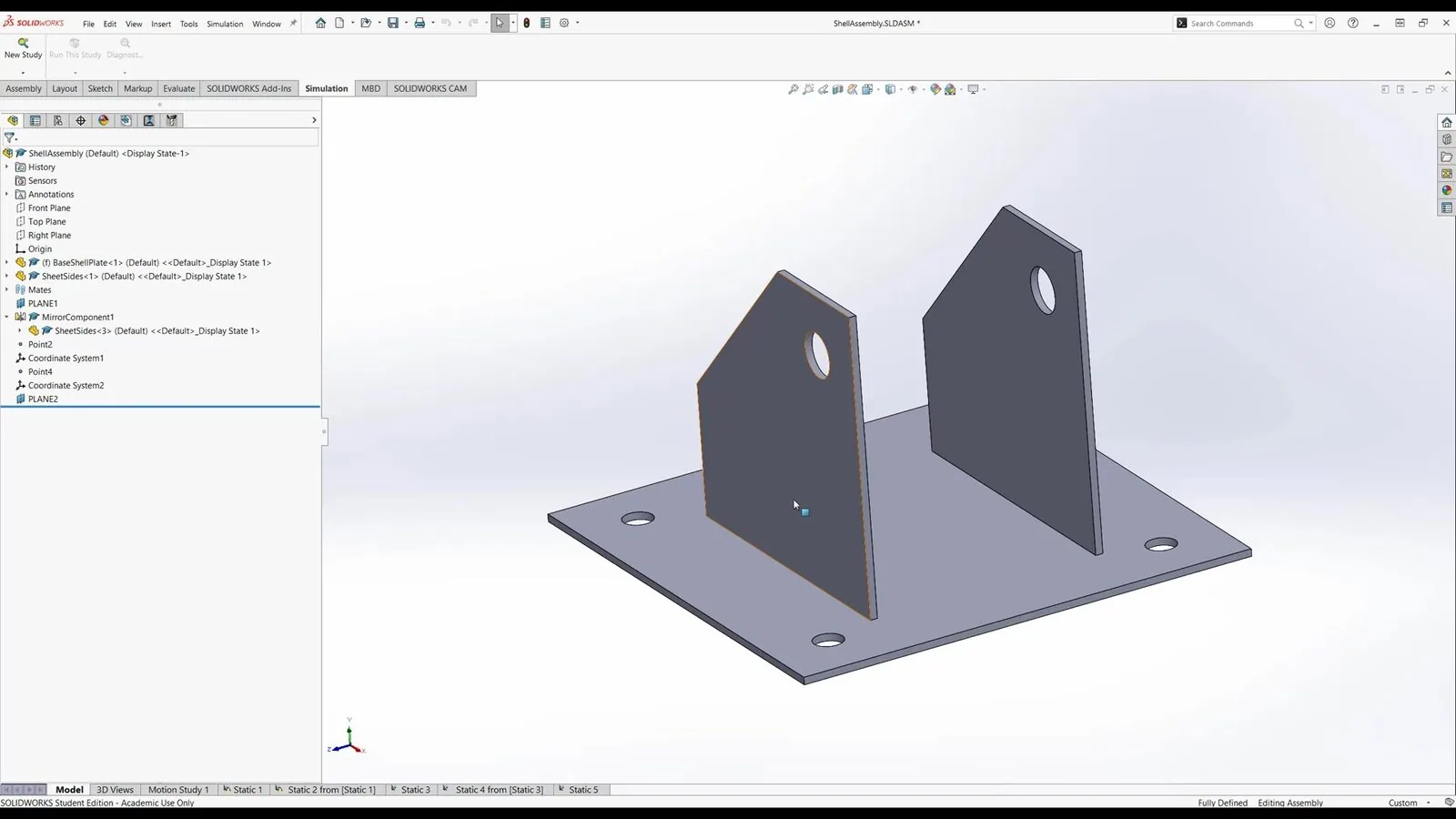
The hand methods of the welds chapter need the force on each weld, and in most parts it is not obvious. In the bracket of Figure 9.17.1, two lugs carry 500 N each on a pin, and four bolts hold the base plate down. How the load spreads along each weld depends on how the plate and the lugs bend: a question for a finite element model. A 3D model of the welds themselves needs a very fine mesh and is worth it only for fatigue. The practical method models the plates as shells joined by weld connectors. The connector takes the force and moment per unit length along the seam, and the program sizes the weld with the directional method of EN 1993-1-8 [1], 9.16.2. In SolidWorks Simulation the Edge Weld Connector needs the Professional or Premium package, which the student edition includes. The pictures are from the video SolidWorks Simulation: Svetsförband, which shows the same steps in Swedish.
Step 1: Turn the plates into shells
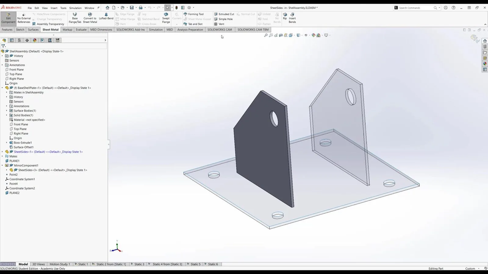
The edge weld connector joins a shell to a shell or to a solid face, so every welded plate must be a shell. The simplest way is sheet metal: open the part, Insert › Sheet Metal › Insert Bends, pick the body and accept; the warning No bends found can be ignored (Figure 9.17.2). Simulation meshes sheet metal as a shell of the sheet thickness without further settings, and the mirrored lug follows its original.
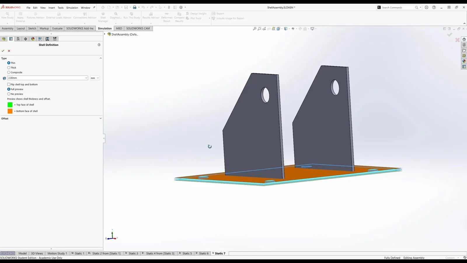
Any solid works too. Create a surface on one face with Insert › Surface › Offset at 0 mm. In the study, exclude the solid body from the analysis, then edit the surface’s definition and give it the plate thickness, 2 mm. Tell Simulation which face the surface lies on: the surface of Figure 9.17.3 was taken from the bottom face, so the shell is offset to the Bottom surface and grows up into the plate. The preview colours the two faces of the shell, so we can see that it lies where the plate is.
Delete the study’s Global Interaction: it would bond the parts, and the welds would carry nothing. The connectors must be the only link between the lugs and the plate. Mesh once and check that the shells of the lugs reach the shell of the plate.
Step 2: Material, loads and fixtures
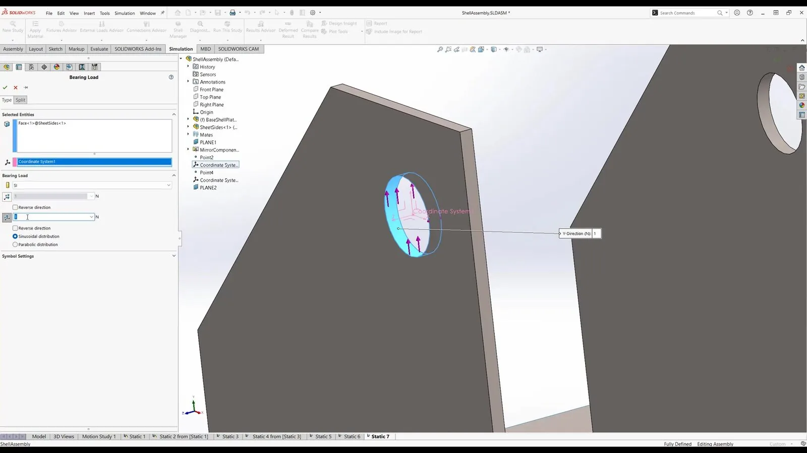
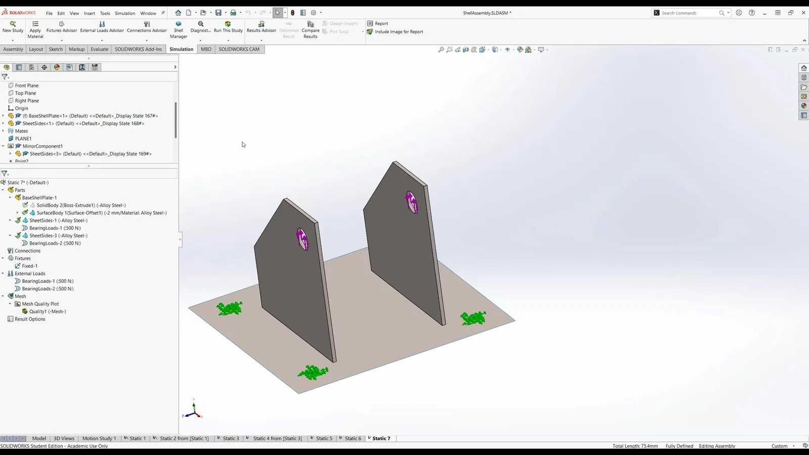
Apply the material first, here Alloy Steel, so that the later dialogs find it. The pin in each lug is a Bearing Load, which spreads the force over the half of the hole the pin presses on (Figure 9.17.4). It needs a coordinate system whose \(z\) axis is the axis of the hole, one per lug. Select the hole face, the coordinate system, and 500 N in \(+y\). On a shell made from an offset surface, select the surface’s edge, not the excluded solid’s.
The bolts are a Fixed Geometry fixture on the four holes of the base plate (Figure 9.17.5), stiffer than real bolts but good enough for sizing the welds.
Step 3: The edge weld connectors
Add one connector per seam with Connections › Edge Weld (Figure 9.17.6). The dialog asks for:
- Weld Type: fillet or groove (butt) weld, double-sided or single-sided. Start with Fillet, Double-Sided, one fillet on each side of the lug.
- Face Set 1: a face of the shell that ends at the weld, here the lug. It must be a shell. For a sheet metal body either face of the sheet will do; for an offset surface, the face the surface lies on.
- Face Set 2: the face it is welded to, here the base plate.
- Intersecting Edges: the edge along which the two meet. SolidWorks usually finds it itself.
- Weld Sizing: European Standard, EN 1993-1-8. Choose the Material of weaker joined part; its ultimate tensile strength \(R_m\) appears below (723.8 MPa for Alloy Steel).
- Correlation Factor \(\beta_w\), 0.8 to 1.0 by steel grade, as in the welds chapter; 1.0 is conservative.
- Partial Safety Factor \(\gamma_{M2}\), 1.25 as EN 1993-1-8 recommends. A larger value adds margin; the study below uses 2.
- Estimated weld size: the throat thickness \(a\) we intend to make. The program compares its result with it; the value does not change the computation.
Check the unit next to a stress before typing it. The dialog may open in psi, and a value in the wrong unit gives nonsense weld sizes without a warning; choosing the material from the list avoids the problem.
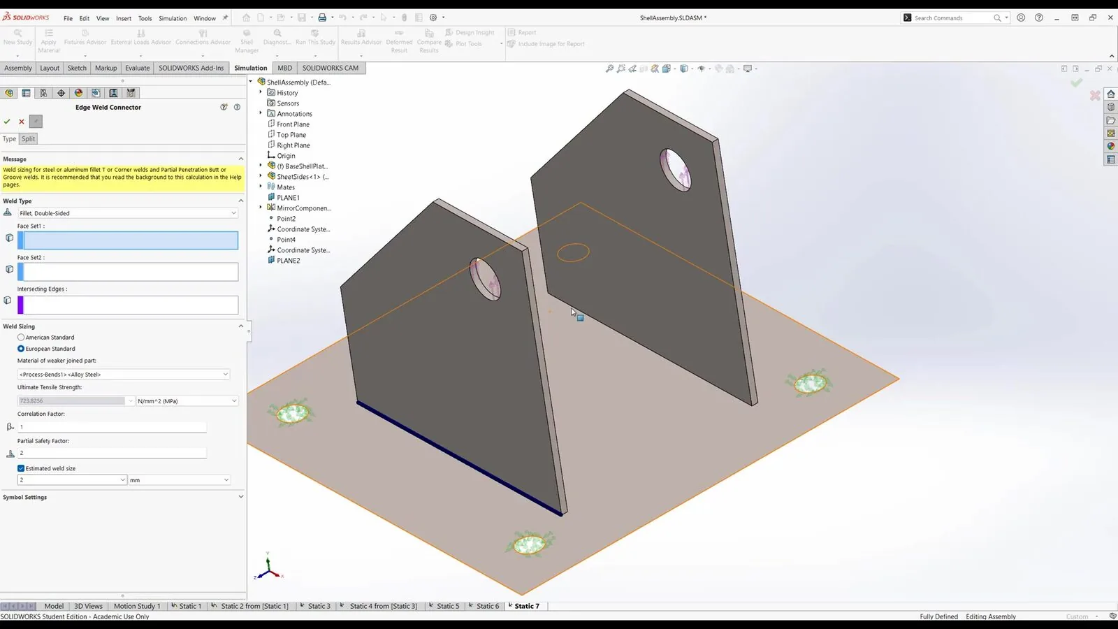
Pin the dialog (Keep Visible) and add the second lug’s weld with the same settings. Then run the study.
Step 4: Read the results
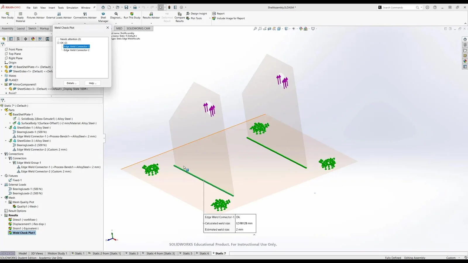
Right-click Results and choose Define Weld Check Plot. Each weld is drawn green when the estimated size is large enough and red when it needs attention (Figure 9.17.7); clicking a weld shows the calculated and the estimated size. Both welds here are green: they need 0.6 mm, and 2 mm was estimated.
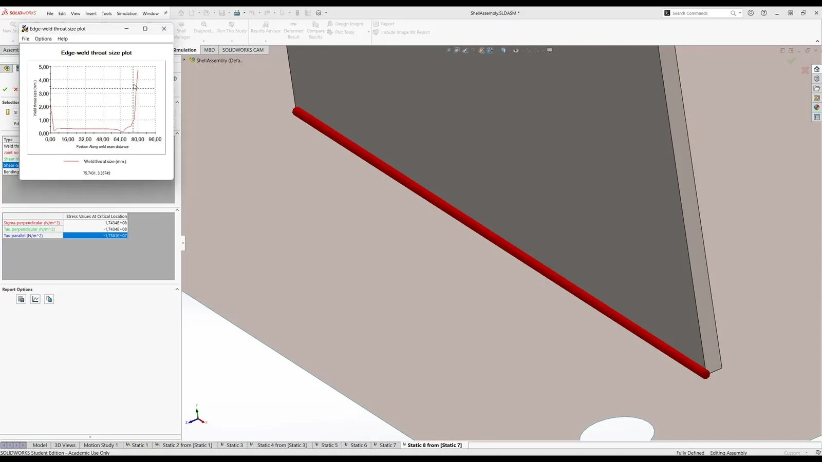
List Weld Results gives the minimum, maximum and mean of the required throat and of the forces per unit length, the throat stresses \(\sigma_\perp\), \(\tau_\perp\) and \(\tau_\parallel\) at the critical location in N/m², and a plot of the required throat along the seam (Figure 9.17.8). The plot is the most useful output: the weld needs 0.2 mm at the start of the seam, 0.6 mm at its end, and almost nothing between. The load runs from the pin to the nearest bolt holes, and only the ends of the seam lie on that path.
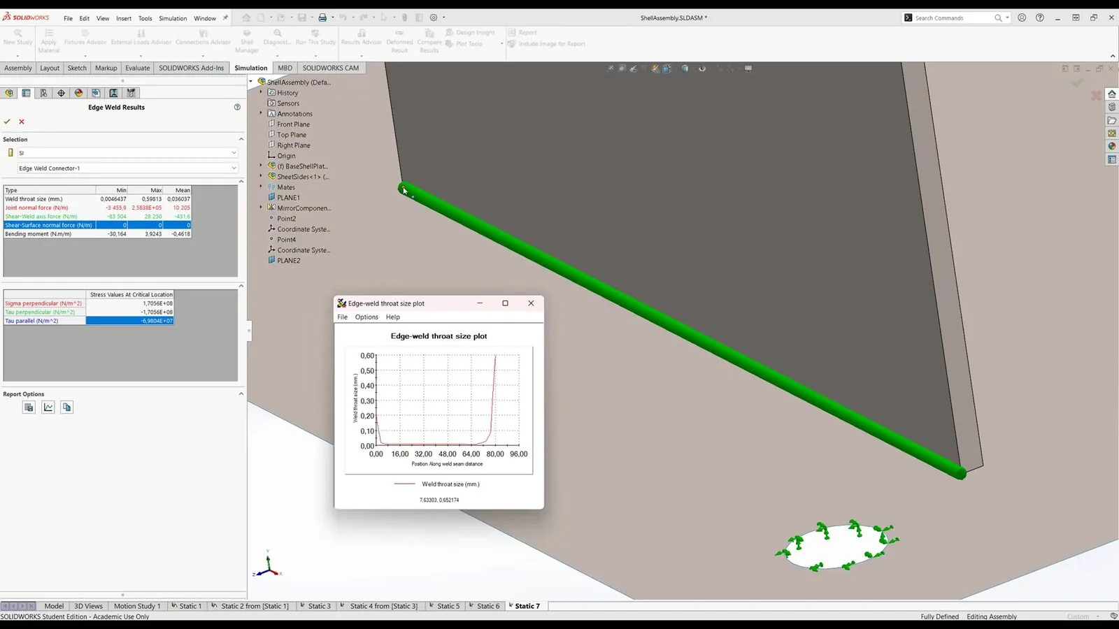
The stresses can be checked by hand. They are the stresses at the critical location for the computed throat size, and inserted in the directional method they give
\[ \sqrt{\sigma_\perp^2 + 3(\tau_\perp^2 + \tau_\parallel^2)} = \sqrt{170.6^2 + 3(170.6^2 + 69.8^2)}~\text{MPa} = 361.9~\text{MPa} = \frac{R_m}{\beta_w\gamma_{M2}} = \frac{723.8}{1 \cdot 2}~\text{MPa} \]
so the program has made the throat exactly as thick as the check allows; the second condition, \(\sigma_\perp \le 0.9\,R_m/\gamma_{M2} = 326\) MPa, holds with margin. The equal \(\sigma_\perp\) and \(\tau_\perp\) show that the load crosses the weld there, as in Example 2 of the welds chapter.
No weld is 0.6 mm. EN 1993-1-8 requires a throat of at least 3 mm, so we lay the smallest weld allowed, and the plot says where it is needed: at the ends of each seam. Short welds at the ends would carry the load as well as a full seam, with less heat and distortion; a full seam may still be chosen to seal the joint or for other load cases.
Step 5: Single-sided welds
Now weld each lug on one side only: copy the study and change each connector to Fillet, Single-Sided (Figure 9.17.9). Weld Orientation says which side of the lug the fillet is on, as on the weld symbol. Include the induced bending moment due to unsymmetry of the joint loading adds the moment a load across a one-sided fillet sets up about its root; always tick it. Put both fillets on the outer sides of the lugs.
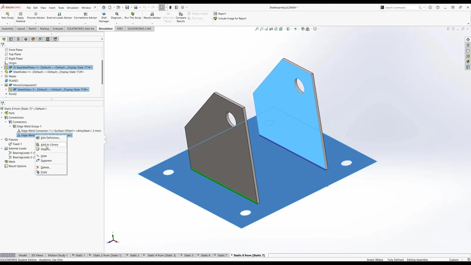
The welds turn red (Figure 9.17.10): they need about 2 mm at the start of the seam and almost 5 mm at its end, eight times the double-sided weld, because the throat is a poor section in bending, as Example 3 of the welds chapter shows. A 5 mm throat on a 2 mm plate is no solution either. Weld both sides, or turn the lug so that the load runs along the weld.
What the method does not do
The connector sizes a weld for static strength by the rules of the standard; it does not resolve the stresses in the weld. The stress at the root and the toe is far higher than the throat stress and governs fatigue, which is checked with the detail categories of EN 1993-1-9 (see Fatigue) or a 3D model that resolves the toe. Shells also assume thin plates; thick plates need solid elements.
Further reading
The SOLIDWORKS help describes every field of the Edge Weld Connector and the formulas behind its American and European weld sizing. The welds chapter derives the throat stresses and the directional method that the connector applies.