9.3 Herringbone Gears in SolidWorks
A helical gear has its teeth cut at an angle \(\beta\) to the axis, so each tooth enters the mesh gradually from one end face to the other and more than one tooth carries load at any instant. The price is an axial force. The tooth normal is inclined to the axis, and a helical pair transmitting a tangential force \(F_t\) pushes its shafts apart axially with \(F_a = F_t\tan\beta\) [1], which the bearings must take. A herringbone gear, or double helical gear, joins two helical halves of opposite hand at its mid-plane. Each half produces its own axial force and the two cancel inside the gear.
For a printed drive this is the gear to use. With the thrust cancelled no thrust bearing is needed, the V of one gear locates the other axially, and the gradual engagement makes a printed pair quieter. Printed with its axis vertical, every flank leans at \(\beta\) from the vertical, so for \(\beta\) below \(45°\) the gear needs no support material.
We build it from the parametric spur gear, and the only new parameter is the helix angle.
The twist
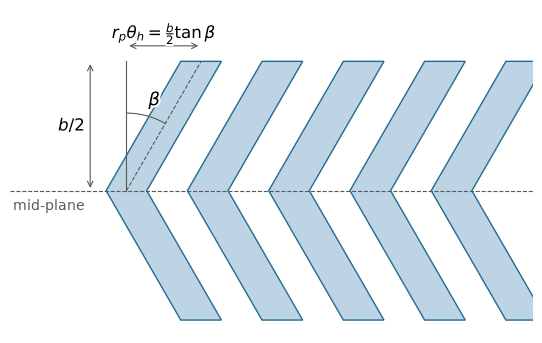
Unrolling the pitch cylinder onto a plane turns every tooth of a helical gear into a straight band inclined at \(\beta\) to the axis, as in Figure 9.3.1. Moving a distance \(z\) along the axis shifts the tooth by \(z\tan\beta\) along the pitch circle, which is a rotation of the transverse section through
\[ \theta(z) = \frac{z\tan\beta}{r_p} = \frac{2z\tan\beta}{d} \tag{9.3.1}\]
where \(d = mN\) is the pitch diameter. The rotation is linear in \(z\), so the tooth trace is a helix, and one full turn takes the axial distance \(L = \pi d/\tan\beta\), the lead. A herringbone gear of face width \(b\) consists of two halves of width \(b/2\), and each turns its section through
\[ \theta_h = \frac{b\tan\beta}{d} \tag{9.3.2}\]
between the mid-plane and its end face, the two halves in opposite senses. The twist depends on \(b\) and \(d\) as well as on \(\beta\). A twist typed into SolidWorks as a fixed number therefore gives a different helix angle as soon as \(N\), \(m\) or the face width changes, and it has to be an equation.
The twisted section also gives the exact flank. Every transverse section of the gear is the transverse profile turned through \(\theta(z)\), so the flank is swept by a planar involute rotating at a constant rate as it advances along the axis. That surface is the involute helicoid, the flank of every involute helical gear [2], and its sections perpendicular to the axis are true involutes of the base circle. A twisted sweep of the spur profile is therefore not an approximation of the helical flank but the flank itself. The sections that are not involutes are those taken normal to the tooth.
Code
import numpy as np
import matplotlib.pyplot as plt
import matplotlib.patheffects as pe

m, N, b, beta = 1, 20, 10, np.radians(30)
p = np.pi * m                     # circular pitch: one tooth and one space
h = b / 2
halo = [pe.withStroke(linewidth=3, foreground='white')]

fig, ax = plt.subplots(figsize=(7, 4.2))
z = np.array([-h, 0, h])
shift = np.abs(z) * np.tan(beta)  # pitch-circle arc length the tooth has moved, per eq-hb-theta
for k in range(0, 5):
    left = k * p - p / 4 + shift
    right = k * p + p / 4 + shift
    ax.fill(np.r_[left, right[::-1]], np.r_[z, z[::-1]],
            facecolor='#bcd4e3', edgecolor='#236b8e', lw=1)

ax.axhline(0, color='0.35', lw=0.8, ls='--')
ax.plot([0, 0], [0, h], color='0.35', lw=0.8)
ax.plot([0, h * np.tan(beta)], [0, h], color='0.35', lw=0.8, ls='--')  # tooth centreline

# helix angle between the axis direction and the tooth centreline
arc = np.linspace(np.pi / 2 - beta, np.pi / 2, 30)
ax.plot(0.6 * h * np.cos(arc), 0.6 * h * np.sin(arc), color='0.35', lw=0.8)
ax.text(0.17 * h, 0.66 * h, r'$\beta$', fontsize=13, path_effects=halo)

# the arc length the section turns through over one half
ax.annotate('', xy=(h * np.tan(beta), h + 0.6), xytext=(0, h + 0.6),
            arrowprops=dict(arrowstyle='<->', color='0.35', lw=0.8))
ax.text(h * np.tan(beta) / 2, h + 0.9, r'$r_p\theta_h = \frac{b}{2}\tan\beta$',
        ha='center', fontsize=12, path_effects=halo)
ax.annotate('', xy=(-1.4, h), xytext=(-1.4, 0),
            arrowprops=dict(arrowstyle='<->', color='0.35', lw=0.8))
ax.text(-1.6, h / 2, r'$b/2$', ha='right', va='center', fontsize=12, path_effects=halo)
ax.text(-1.6, -0.6, 'mid-plane', ha='right', va='center', fontsize=10, color='0.35')

ax.set_xlim(-4.5, 5 * p)
ax.set_ylim(-h - 0.5, h + 2)
ax.set_aspect('equal')
ax.axis('off')
plt.show()The helix also sets how many teeth share the load. The axial distance between neighbouring teeth is the axial pitch \(p_x = \pi m/\tan\beta\), and the face width measured in axial pitches is the overlap ratio
\[ \varepsilon_\beta = \frac{b\tan\beta}{\pi m} \tag{9.3.3}\]
A spur gear has \(\varepsilon_\beta = 0\). Once it exceeds one, some part of a tooth is in contact at every instant across the face, independently of the transverse contact ratio. For the gear of Figure 9.3.2, with \(N = 20\), \(m = 1\) mm, \(b = 10\) mm and \(\beta = 30°\), 9.3.2, the lead and 9.3.3 give
Code
import sympy as sp
from mechanicskit import ltx

m_, N_, b_, beta_ = 1, 20, 10, sp.rad(30)
d_ = m_ * N_
theta_h = b_ * sp.tan(beta_) / d_
L_ = sp.pi * d_ / sp.tan(beta_)
eps_beta = b_ * sp.tan(beta_) / (sp.pi * m_)

ltx(r"\theta_h =", sp.deg(theta_h).evalf(4), r"^\circ,\quad L =", L_.evalf(4),
    r"~\text{mm},\quad \varepsilon_\beta =", eps_beta.evalf(3))
\[ \theta_h =16.54^\circ,\quad L =108.8~\text{mm},\quad \varepsilon_\beta =1.84 \]
so the twist each half needs is modest, a little under one angular pitch of \(18°\), and nearly two teeth overlap across the face.
Code
from mpl_toolkits.mplot3d.art3d import Poly3DCollection
from gear_geometry import gear_profile_points

P = gear_profile_points(N_teeth=20, module=1)[::2, :2]
z = np.linspace(-h, h, 41)
theta = 2 * np.abs(z) * np.tan(beta) / (m * N)      # eq-hb-theta, mirrored at the mid-plane
X = np.cos(theta)[:, None] * P[:, 0] - np.sin(theta)[:, None] * P[:, 1]
Y = np.sin(theta)[:, None] * P[:, 0] + np.cos(theta)[:, None] * P[:, 1]
Z = np.repeat(z[:, None], len(P), axis=1)

fig = plt.figure(figsize=(5.5, 5.5))
ax = fig.add_subplot(projection='3d')
ax.plot_surface(X, Y, Z, color='#bcd4e3', edgecolor='none', shade=True,
                rstride=1, cstride=1, antialiased=False)
ax.add_collection3d(Poly3DCollection([np.column_stack([X[-1], Y[-1], Z[-1]])],
                                     facecolor='#bcd4e3', edgecolor='#236b8e', lw=0.6))
ax.set_box_aspect((1, 1, b / (m * (N + 2))))
ax.view_init(elev=25, azim=-60)
ax.set_axis_off()
plt.show()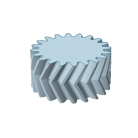
Transverse and normal module
The profile we sweep is the transverse one, so the module \(m\) and pressure angle \(\varphi\) of the spur model become the transverse module and transverse pressure angle of the helical gear. Two gears built from the model mesh at the spur centre distance \(a = m(N_1 + N_2)/2\), and for a printed pair that is all we need.
A hob cuts in the plane normal to the tooth, so a bought helical gear is specified by its normal module \(m_n\) and normal pressure angle \(\varphi_n\). The transverse values follow as
\[ m = \frac{m_n}{\cos\beta}, \qquad \tan\varphi = \frac{\tan\varphi_n}{\cos\beta} \tag{9.3.4}\]
[1], while the addendum and dedendum stay at \(m_n\) and \(1.25\,m_n\). At \(\beta = 30°\) and \(\varphi_n = 20°\) this gives \(m = 1.155\,m_n\) and \(\varphi = 22.80°\). To mesh with such a gear we enter these two values for m and PressureAngle and write TipRadius and RootRadius in terms of \(m_n\).
Building the gear in SolidWorks
We start from the finished spur gear part of the spur gear procedure. Its solid supplies the transverse profile, and the herringbone is built as a second body beside it.
Add two global variables to the equations,
| Variable | Expression | Meaning |
|---|---|---|
HelixAngle |
30 |
Helix angle \(\beta\) (degrees) |
Twist |
"FaceWidth" * tan("HelixAngle") / ("m" * "N") * 180 / pi |
Twist of each half, \(\theta_h\) (degrees) |
where Twist is 9.3.2 converted to degrees, with FaceWidth as the full width \(b\) of the herringbone.
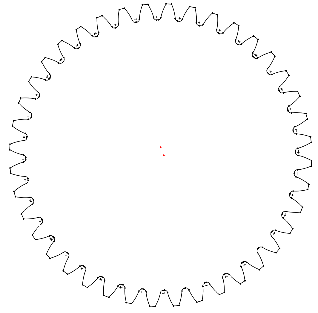
Open a sketch on the Top Plane, select the face of the spur gear that lies in that plane, and use Convert Entities. The sketch now holds the complete closed outline of the gear, flanks, root fillets and tip arcs, and it follows the solid through every change of \(N\) (Figure 9.3.3). This is the one reference to a model face in the construction, which the spur gear chapter warns against, so it is the first thing to check when a rebuild fails. Then open a second sketch on the Front Plane and draw a line from the origin along the gear axis, normal to the Top Plane, of length "FaceWidth" / 2.
Sweep the outline along the line with Insert, Boss/Base, Sweep. Under Options set Profile Twist to Specify Twist Value, Twist Control to Degrees, and enter = "Twist" in the angle field. Clear Merge result, so the sweep becomes a body of its own instead of fusing with the spur solid it overlaps (Figure 9.3.4).
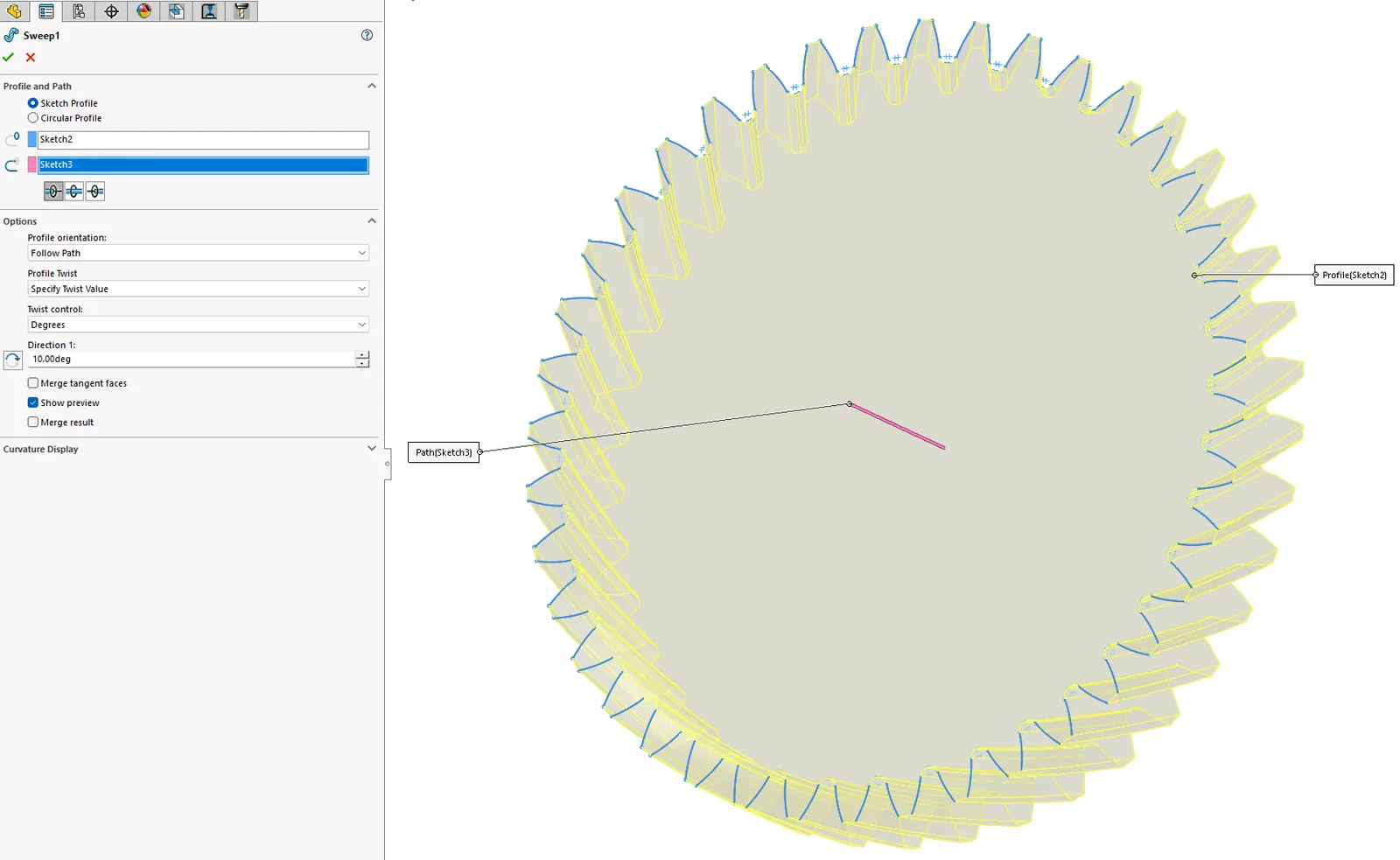
The profile turns about the path, which is why the path starts at the origin and runs along the axis; a path anywhere else would swing the gear off centre as it twisted. Then remove the spur solid with Insert, Features, Delete/Keep Body, keeping the sweep (Figure 9.3.5). The converted sketch still resolves, since it comes before the deletion in the feature tree.
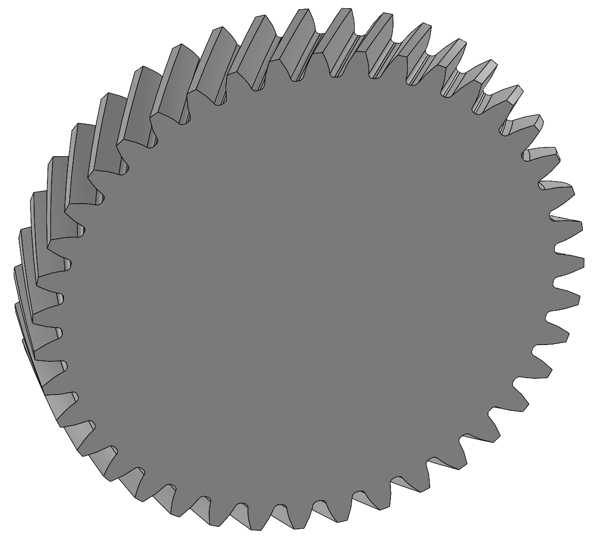
Finally mirror the sweep with Insert, Pattern/Mirror, Mirror, taking the Top Plane as the mirror plane, the sweep under Bodies to Mirror, and Merge solids checked. A reflection in a plane perpendicular to the axis reverses the hand of a helix, so the mirrored half twists the other way and the two halves meet in the V at the Top Plane, now the mid-plane of the gear. Both halves come from one sweep, so they agree by construction.
Two meshing herringbone gears have opposite hands, the V of one pointing into the V of the other. The mating gear is a copy of the part with its own N and the angle field set to = -"Twist", the sign of the twist setting the hand.
Checking the model
Rebuild at \(N = 12\) and \(N = 50\) as for the spur gear, which also exercises the face reference of the converted sketch. Then check the twist itself. In a sketch on the outer end face, draw one line from the origin to the midpoint of a tip arc and a second to the midpoint of the same tooth’s tip arc in the Top Plane sketch. The angle between them must equal Twist, \(16.54°\) for the gear of Figure 9.3.2.
Lofts and flex
Two other constructions recur in tutorials, and both fall short of the twisted sweep. A loft between the end profile and a turned copy of it, with two profiles and no end conditions, joins corresponding points with straight lines. A straight chord between two points at radius \(r\) turned through \(\theta_h\) passes at \(r\cos(\theta_h/2)\) halfway along, which for our example is \(0.10\) mm inside the pitch circle, the flank sagging away from the helix by half the height of a typical \(0.2\) mm printed layer. The Flex feature in its twisting mode deforms a finished spur gear instead, but it fits new surfaces to the deformed faces, and its angle is the twist, so it still needs 9.3.2 to be fed the right value. The sweep generates the helicoid directly and takes its angle from an equation.
References
[1]
Budynas RG, Nisbett JK. Shigley’s mechanical engineering design. 11th ed. New York: McGraw-Hill Education; 2020.
[2]
Litvin FL, Fuentes A. Gear geometry and applied theory. 2nd ed. Cambridge: Cambridge University Press; 2004.