A tensile test gives one number for the strength of a material: the stress at which the specimen starts to deform permanently, or the stress at which it breaks. A machine part is seldom loaded that way. The surface of a drive shaft carries a bending stress and a torsional shear stress at the same point, and the wall of a pressure vessel is stretched around its circumference and along its axis at once. Chapter 8.7 described such a state by a stress tensor with six components, and this chapter asks how those six components are to be compared with the single number from the tensile test.
The answer is a yield criterion, a rule built on a hypothesis about what makes a material fail, which turns the stress tensor into one effective stress that can be compared with the strength. We first state the question, then reduce the stress state to its three principal stresses, and develop the three classical criteria: the maximum normal stress criterion for brittle materials, and the maximum shear stress criterion of Tresca and the distortion energy criterion of von Mises for ductile ones. We compare the three in plane stress and in principal stress space, discuss which to use when, and close with two examples. The chapter ends at the onset of yielding. What a ductile material does after it has started to yield is the subject of plasticity.
What failure means
For a ductile material such as structural steel, aluminium or copper, a part has failed for most design purposes once it starts to yield. Yielding is permanent deformation: a shaft that has yielded no longer runs true, a bolt that has yielded has lost part of its preload, and the part no longer has the shape it was designed with, even though it may carry a much larger load before it breaks. A brittle material such as cast iron, glass or concrete deforms hardly at all before it breaks, and for it failure means fracture.
In the tensile test of Chapter 8.6 both events are easy to locate. The specimen carries a uniaxial stress \(\sigma\). A ductile specimen yields when \(\sigma\) reaches the yield strength, which we write \(\sigma_\text{Y}\), and a brittle one breaks when \(\sigma\) reaches the ultimate tensile strength\(R_m\). The upright subscript keeps the yield strength apart from the stress component \(\sigma_y\). In the notation of the standards, \(\sigma_\text{Y}\) is the offset yield strength \(R_{p0.2}\) or, for a steel with a distinct yield point, the upper yield strength \(R_{eH}\).
A general stress state has no single \(\sigma\) to compare with \(\sigma_\text{Y}\). A point on the surface of the shaft carries a normal stress and a shear stress together, and nothing in the tensile test says at which combination of the two it yields. With six stress components, testing every combination is out of the question. We need a rule that predicts failure under any stress state from the uniaxial test. Such a rule is a failure criterion, for ductile materials a yield criterion. It is a hypothesis about the mechanism of failure, different hypotheses give different criteria, and experiments decide which of them describes which class of materials [1].
where the effective stress\(\sigma_e\) is a scalar function of the stress tensor, scaled so that it equals \(\sigma\) in a uniaxial test. While \(\sigma_e < \sigma_\text{Y}\) the material is elastic, and yielding starts when \(\sigma_e\) reaches \(\sigma_\text{Y}\). The factor of safety against yielding is the ratio
\[
n = \frac{\sigma_\text{Y}}{\sigma_e}
\tag{8.10.2}\]
Every effective stress below scales in proportion to the stresses, and in a linear elastic analysis every stress grows in proportion to the load. Hence \(n\) is also the factor by which the load can grow before the part starts to yield.
The principal stresses are enough
A symmetric stress tensor has three real eigenvalues, the principal stresses, and three orthogonal eigenvectors, the principal directions, 8.7.10, and we number them by size as in 8.7.20. In the frame of the principal directions there is no shear, and the stress state is three normal stresses,
For an isotropic material, one with the same properties in every direction, the orientation of the principal frame cannot matter. Turning the whole stress state relative to the material changes nothing the material can respond to. A criterion for an isotropic material is therefore a function of the three principal stresses alone, \(\sigma_e = \sigma_e(\sigma_1, \sigma_2, \sigma_3)\), and the same function whatever the order in which the three are listed. Six components have become three numbers, and each criterion below is a different choice of the function. Materials that are not isotropic, printed parts among them, are taken up in the discussion of which criterion to use.
The maximum normal stress criterion
The simplest hypothesis is that a material fails when its largest tensile stress reaches the tensile strength, or its largest compressive stress reaches the compressive strength, whatever the other principal stresses are. With \(R_m\) the ultimate strength in tension and \(R_c\) in compression, the maximum normal stress criterion reads
It is also called the maximum principal stress criterion, or Rankine’s criterion after the Scottish engineer William Rankine. For brittle materials it works well. A brittle material fails by a crack that opens under tension, and the crack grows perpendicular to the largest principal stress. A stick of chalk twisted between the fingers shows this, Figure 8.10.1. In pure torsion the principal directions lie at \(45^\circ\) to the axis, and chalk breaks along a helix at \(45^\circ\), the surface perpendicular to \(\sigma_1\).
Figure 8.10.1: Two bars twisted to fracture by the torque \(M_t\), drawn as double-headed vectors. A brittle bar breaks along a helix at \(45^\circ\) to its axis, perpendicular to the largest principal stress; the dashed part of the crack runs on the far side. A ductile bar breaks across its cross-section, the plane of the largest shear stress.
A ductile steel bar twisted to failure breaks across its cross-section instead, on the plane where the shear stress is largest. That hints at why the criterion fails for ductile metals, and two simple states show by how much. In pure shear the principal stresses are \(\sigma_1 = \tau\), \(\sigma_2 = 0\) and \(\sigma_3 = -\tau\), as we found for Figure 8.9.1, and 8.10.3 with \(\sigma_\text{Y}\) in place of \(R_m\) predicts yielding at \(\tau = \sigma_\text{Y}\). Torsion tests on ductile metals give a shear yield strength between about \(0.5\sigma_\text{Y}\) and \(0.6\sigma_\text{Y}\)[1]. The criterion overestimates the strength in shear by a factor close to two. Under hydrostatic compression, \(\sigma_1 = \sigma_2 = \sigma_3 = -p\), it predicts yielding at \(p = \sigma_\text{Y}\), some \(300~\text{MPa}\) for a structural steel, while metals in pressure tests have been taken far beyond their yield strength without any permanent change of shape [1]. Ductile metals yield by a different mechanism, and the criterion for them has to describe it.
The maximum shear stress criterion
A metal is a polycrystal, and each of its grains deforms plastically by slip: planes of atoms slide over one another, carried along by line defects called dislocations. Slip is driven by the shear stress on the slip plane, while the normal stress across the plane has little influence on it. In a polished tensile specimen of mild steel the first plastic deformation is visible as bands at about \(45^\circ\) to the axis, the Lüders bands, along the planes of the largest shear stress.
The French engineer Henri Tresca1 drew the conclusion from his experiments on metals forced through dies, published in 1864 [2]: a ductile material yields when its largest shear stress reaches a critical value. The largest shear stress over all planes through a point is half the difference between the largest and the smallest principal stress, 8.7.14,
\[
\tau_{\max} = \frac{\sigma_1 - \sigma_3}{2}
\]
and the critical value comes from the tensile test, where \(\sigma_1 = \sigma_\text{Y}\) and \(\sigma_2 = \sigma_3 = 0\) at yield, so that \(\tau_{\max} = \sigma_\text{Y}/2\). Equating the two gives the Tresca criterion
with the Tresca effective stress\(\sigma_\text{T}\), twice the largest shear stress. Pressure vessel engineers know it as the stress intensity.
Two properties follow from the form of 8.10.4. The intermediate principal stress \(\sigma_2\) does not enter at all. And adding the same pressure to all three principal stresses, \(\sigma_k \to \sigma_k - p\), leaves the difference \(\sigma_1 - \sigma_3\) unchanged, so a hydrostatic pressure has no effect on yielding, as the pressure tests found. On Mohr’s circles 8.10.4 compares the diameter of the largest circle with that of the tensile test at yield, which is why \(\sigma_2\) and a hydrostatic pressure leave it unchanged, Figure 8.8.5. In pure shear \(\sigma_1 - \sigma_3 = 2\tau\), and Tresca predicts the shear yield strength
Tresca’s criterion ignores the hydrostatic part of the stress by construction. The von Mises criterion builds that property in from the start. It splits the stress into a part that changes the volume of the material and a part that changes its shape, and lets only the second one cause yielding.
Volume change and shape change
The mean stress, which Chapter 8.9 used to define the bulk modulus, is the average of the three normal stresses,
where the two forms agree because the trace is the same in every frame. The deviatoric stress, or stress deviator, is what is left when the mean stress is taken off the diagonal,
\[
\bm s = \bm\sigma - \sigma_m\bm I
\tag{8.10.7}\]
so that every stress state is the sum \(\bm\sigma = \sigma_m\bm I + \bm s\), Figure 8.10.2. The first term is a hydrostatic stress, the same tension or pressure in all directions and no shear on any plane, the state of a body submerged in a fluid. The deviator keeps all the shear components of \(\bm\sigma\) and has a zero trace, and in the principal frame its entries are \(s_k = \sigma_k - \sigma_m\) with \(s_1 + s_2 + s_3 = 0\).
Figure 8.10.2: A principal stress state split into its hydrostatic part, the mean stress \(\sigma_m\) on every face, and its deviatoric part, whose three normal stresses add up to zero. An arrow leaving a face is tension, one pointing into it compression. The dashed outlines show, exaggerated, what each part does to a cube of linear elastic material: the hydrostatic part changes its volume and keeps its shape, the deviatoric part changes its shape and keeps its volume.
Hooke’s law keeps the two parts apart. The trace of 8.9.7 is \(\operatorname{tr}\bm\sigma = (3\lambda + 2\mu)\operatorname{tr}\bm\varepsilon\), and since \(3\lambda + 2\mu = 3K\) with the bulk modulus \(K\) of 8.9.3,
\[
\sigma_m = K\operatorname{tr}\bm\varepsilon
\]
Subtracting \(\sigma_m\bm I\) from 8.9.7 leaves the deviatoric part,
\[
\bm s = 2G\,\bm e, \qquad \bm e = \bm\varepsilon - \tfrac{1}{3}\operatorname{tr}(\bm\varepsilon)\,\bm I
\]
where \(\bm e\) is the deviatoric strain and \(G = \mu\) the shear modulus. The mean stress produces only the volume change \(\operatorname{tr}\bm\varepsilon\) of 8.9.9, and the deviator only the strain \(\bm e\), whose zero trace means a change of shape at constant volume.
Volumetric and distortional strain energy
The work done on a unit volume of linear elastic material while it is loaded is stored as strain energy. In one dimension it is the area under the straight stress-strain line, \(\tfrac{1}{2}\sigma\varepsilon\). In three dimensions each stress component works on its own strain component, and the energy per unit volume is
\[
W = \tfrac{1}{2}\,\bm\sigma : \bm\varepsilon = \tfrac{1}{2}\sum_{i,j}\sigma_{ij}\varepsilon_{ij}
\tag{8.10.8}\]
where the double dot \(\bm A : \bm B = \sum_{i,j} A_{ij}B_{ij}\) is the sum of the products of corresponding entries. Inserting \(\bm\sigma = \sigma_m\bm I + \bm s\) and \(\bm\varepsilon = \tfrac{1}{3}\operatorname{tr}(\bm\varepsilon)\bm I + \bm e\), the two mixed products vanish, since \(\bm I : \bm e = \operatorname{tr}\bm e = 0\) and \(\bm s : \bm I = \operatorname{tr}\bm s = 0\), and what is left is
\[
W = \tfrac{1}{2}\sigma_m\operatorname{tr}\bm\varepsilon + \tfrac{1}{2}\,\bm s : \bm e
= \underbrace{\frac{\sigma_m^2}{2K}}_{W_v} + \underbrace{\frac{\bm s : \bm s}{4G}}_{W_d}
\tag{8.10.9}\]
The strain energy splits into a volumetric part \(W_v\), set by the mean stress alone, and a distortional part
\[
W_d = \frac{\bm s : \bm s}{4G}
\tag{8.10.10}\]
set by the deviator alone. We confirm 8.10.9 for a general stress state, computing the strain from the inverse Hooke’s law 8.9.8.
\[ \operatorname{tr}\bm s =0,\qquad W - W_v - W_d =0 \]
Both vanish for every stress state: the deviator carries no volume change, and 8.10.9 holds identically.
The von Mises criterion
The distortion energy criterion states that a ductile material yields when its distortion energy reaches the value it has at yield in the tensile test. In the principal frame the deviator is diagonal, and its double dot product with itself depends only on the differences of the principal stresses,
In the tensile test at yield, \(\sigma_1 = \sigma_\text{Y}\) and \(\sigma_2 = \sigma_3 = 0\), so \(\bm s : \bm s = \tfrac{2}{3}\sigma_\text{Y}^2\) and the distortion energy is \(W_d = \sigma_\text{Y}^2/(6G)\). Setting the distortion energy of a general state equal to this value, the shear modulus cancels and the condition becomes \(\tfrac{3}{2}\,\bm s : \bm s = \sigma_\text{Y}^2\), or
This is the von Mises criterion, and \(\sigma_\text{vM}\) is the von Mises effective stress. Inserting 8.10.11 gives the effective stress in the principal stresses,
In a frame that is not principal, the stress tensor also has shear components, and expanding \(\bm s : \bm s\) in all six independent components of \(\bm\sigma\) gives
The two expressions give the same number for the same stress state, since \(\sigma_\text{vM}\) does not depend on the frame: rotating to the principal frame removes the shear terms of 8.10.14 and leaves 8.10.13. In plane stress, \(\sigma_z = \tau_{yz} = \tau_{zx} = 0\), and 8.10.14 reduces to
the form of most hand calculations and of a finite element post-processor’s default plot. These are the formulas that Chapter 8.7 stated without derivation, 8.7.21, 8.7.22 and 8.7.23. We check the first two against 8.10.12.
\[ \begin{aligned}\tfrac{3}{2}\,\bm s:\bm s - \sigma_\text{vM}^2\big|_\text{general} &=0\\ \tfrac{3}{2}\,\bm s:\bm s - \sigma_\text{vM}^2\big|_\text{principal} &=0\end{aligned} \]
The elastic constants have dropped out, and like Tresca’s criterion the von Mises criterion needs only the yield strength from the tensile test. The idea of measuring the approach to yield by the distortion energy goes back to Maxwell, Huber and Hencky, while von Mises arrived at the same expression in 1913 as a smooth function close to Tresca’s [3]. The criterion is therefore also called the Huber-von Mises-Hencky criterion. Plasticity theory writes it with the second invariant of the deviator, \(J_2 = \tfrac{1}{2}\,\bm s : \bm s\), as \(\sigma_\text{vM} = \sqrt{3J_2}\), and calls it the \(J_2\) criterion. The same expression is also proportional to the shear stress on the planes equally inclined to the three principal directions, the octahedral planes, which gives it a third name, the octahedral shear stress criterion [1].
In pure shear, \(\sigma_1 = \tau\), \(\sigma_2 = 0\), \(\sigma_3 = -\tau\), 8.10.13 gives \(\sigma_\text{vM} = \sqrt{3}\,\tau\), and the shear yield strength is
Under a hydrostatic stress \(\bm\sigma = -p\,\bm I\) the deviator is zero, so \(W_d = 0\) and \(\sigma_\text{vM} = 0\) whatever the pressure. A hydrostatic pressure slides all three Mohr’s circles along the \(\sigma\) axis without changing their radii, and both criteria depend only on the radii, 8.8.6. At the bottom of the Mariana Trench, almost \(11~\text{km}\) down, the water pressure is \(p = \rho g h \approx 1025 \cdot 9.81 \cdot 10\,900~\text{Pa} \approx 110~\text{MPa}\). A steel part lowered there is compressed uniformly and shrinks in volume by \(p/K\), about \(0.06~\%\) with \(K = 175~\text{GPa}\), but it is not distorted and does not yield, because all its principal stresses are the same. Tresca’s criterion says the same, and the normal stress criterion is the one that got it wrong. The hull of a submarine can still fail at depth, but by buckling: the pressure acts on the outside of a thin shell only, and the stress in the shell wall is far from hydrostatic.
The opposite case needs a word of caution. Equal tension in all three directions is also hydrostatic, and both Tresca and von Mises predict that it never causes yielding. The prediction is right, but a material that cannot relieve such a state by yielding fails by fracture instead, and a ductile metal under strong triaxial tension, such as the material at the root of a sharp notch in a thick plate, can break with little plastic deformation [4]. A yield criterion says when yielding starts, and nothing about fracture.
Comparing the criteria
The yield loci in plane stress
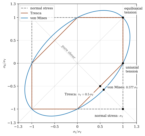
Most design checks are made at a free surface, where the state is plane stress. In this section \(\sigma_\text{I}\) and \(\sigma_\text{II}\) denote the two in-plane principal stresses of 8.7.12, taken in either order so that the diagram covers every combination of signs, and the principal stress normal to the surface is zero. The names \(\sigma_1 \ge \sigma_2 \ge \sigma_3\) stay reserved for the three principal stresses in order, 8.7.20, and the zero takes whichever of the three places the signs of the in-plane pair give it, as the chapter on stress and strain states showed. Each criterion then becomes a closed curve in the \(\sigma_\text{I}\)-\(\sigma_\text{II}\) plane, the yield locus. States inside it are elastic, and states on it are at the onset of yielding.
For Tresca the three principal stresses are \(\sigma_\text{I}\), \(\sigma_\text{II}\) and \(0\), and which of them is \(\sigma_1\) and which \(\sigma_3\) depends on the quadrant,
When both in-plane stresses are tensile, zero is the smallest of the three and the larger in-plane stress decides. When they have opposite signs, the smallest is the negative in-plane stress and their difference decides. The locus is a hexagon. For von Mises, 8.10.15 in the principal frame, where \(\tau_{xy} = 0\), gives
an ellipse with its long axis along the line \(\sigma_\text{I} = \sigma_\text{II}\). The normal stress criterion with the same strength in tension and compression, \(\max(|\sigma_\text{I}|, |\sigma_\text{II}|) = \sigma_\text{Y}\), is a square. Figure 8.10.3 draws all three.
Figure 8.10.3: The plane stress yield loci, with \(\sigma_\text{I}\) and \(\sigma_\text{II}\) the in-plane principal stresses and a zero principal stress normal to the plane. The Tresca hexagon is inscribed in the von Mises ellipse and touches it at uniaxial and equibiaxial tension and compression. The dotted lines are the paths of pure shear, \(\sigma_\text{II} = -\sigma_\text{I}\), and of equal biaxial stress, \(\sigma_\text{II} = \sigma_\text{I}\).
The six corners of the hexagon lie on the ellipse. Two pairs of them are uniaxial tension and compression, where both criteria were calibrated. The third pair is equibiaxial tension and compression, \(\sigma_\text{I} = \sigma_\text{II} = \sigma\), and the criteria agree there too: the state \((\sigma, \sigma, 0)\) is the hydrostatic tension \(\sigma\) plus a uniaxial compression \((0, 0, -\sigma)\), and both criteria ignore the hydrostatic part.
Between the corners the hexagon lies inside the ellipse, and Tresca is the more conservative of the two. To find the largest gap, we fix \(\sigma_1\) and \(\sigma_3\) and let \(\sigma_2 = \sigma_3 + x(\sigma_1 - \sigma_3)\) vary between them, with \(0 \le x \le 1\). Tresca’s effective stress stays \(\sigma_1 - \sigma_3\), while 8.10.13 gives \(\sigma_\text{vM} = (\sigma_1 - \sigma_3)\sqrt{1 - x + x^2}\), smallest at \(x = \tfrac{1}{2}\), where the root is \(\sqrt{3}/2\). Hence
The two criteria never differ by more than \(15.5~\%\), and they differ by that much when the intermediate principal stress lies midway between the other two. Pure shear \((\tau, 0, -\tau)\) is such a state, and so is \((\sigma, \sigma/2, 0)\), which is the pure shear \((\sigma/2, 0, -\sigma/2)\) plus the hydrostatic tension \(\sigma/2\). Example 2 below meets it in a pressure vessel.
The normal stress criterion coincides with Tresca in the first and third quadrants, where the in-plane stresses have the same sign. In the second and fourth quadrants it lies far outside both, and in pure shear it allows twice Tresca’s shear stress. For a ductile material those are the quadrants where it is unsafe. Table 8.10.1 collects the three predictions for pure shear.
Table 8.10.1: The shear yield strength predicted by the three criteria and measured in torsion tests.
Experiments on ductile metals decide between Tresca and von Mises. Taylor and Quinney loaded thin-walled tubes of copper, aluminium and mild steel in combined tension and torsion, a path through the fourth quadrant from uniaxial tension to pure shear, and found their yield points between the two loci and close to von Mises [5]. Tests on many other metals agree [1]. Von Mises describes the onset of yielding of ductile metals somewhat better, and Tresca is never off by more than \(15.5~\%\) and always on the safe side.
The yield surface in principal stress space
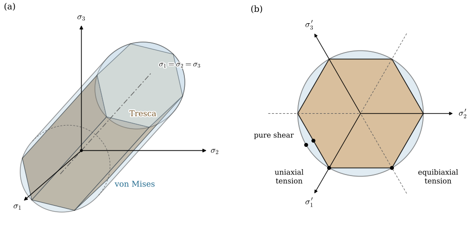
In three dimensions each criterion is a surface in the space with axes \(\sigma_1\), \(\sigma_2\) and \(\sigma_3\), the yield surface, Figure 8.10.4. This space is called the Haigh–Westergaard stress space, after the two who introduced it. Every stress state of an isotropic material is a point in this space. The elastic states lie inside the surface and the states at the onset of yielding on it. The line \(\sigma_1 = \sigma_2 = \sigma_3\) through the origin, the hydrostatic axis, holds the hydrostatic states, and moving a point parallel to it changes the mean stress and nothing else. Since neither Tresca nor von Mises depends on the mean stress, both surfaces are unchanged by such a move: they are prisms parallel to the hydrostatic axis and open at both ends.
Figure 8.10.4: The yield surfaces in principal stress space. (a) The von Mises criterion is a circular cylinder about the hydrostatic axis \(\sigma_1 = \sigma_2 = \sigma_3\), and the Tresca criterion a hexagonal prism inscribed in it; both continue without end in either direction along the axis. (b) The same two surfaces seen along the hydrostatic axis, in the deviatoric plane, with the projections \(\sigma_k'\) of the principal axes. The corners of the hexagon are the uniaxial states. In pure shear the circle lies \(2/\sqrt3\) times as far out as the hexagon.
Their cross-section is seen in the deviatoric plane through the origin, perpendicular to the hydrostatic axis, which holds the states with \(\sigma_m = 0\). The distance of a stress point from the hydrostatic axis is the length of its deviator, \(\sqrt{\bm s : \bm s}\), and 8.10.12 fixes that length at
\[
\sqrt{\bm s : \bm s} = \sqrt{\tfrac{2}{3}}\,\sigma_\text{Y}
\]
The von Mises surface is therefore a circular cylinder of radius \(\sqrt{2/3}\,\sigma_\text{Y}\) about the hydrostatic axis. The Tresca surface is a regular hexagonal prism inscribed in it, with its edges along the uniaxial states. The axes of this space carry the three principal stresses in no particular order. The ordering \(\sigma_1 \ge \sigma_2 \ge \sigma_3\) of 8.7.20 picks out one of six sectors, and since an isotropic criterion does not care about the order, the surfaces repeat the same shape in all six. The plane stress loci of Figure 8.10.3 are the cuts of the two surfaces by a coordinate plane on which one principal stress vanishes, a plane that crosses the hydrostatic axis at an angle, and an oblique cut through a circular cylinder is an ellipse.
A criterion for brittle materials depends on the mean stress, since tension opens cracks and compression closes them, and its surface narrows along the hydrostatic axis toward the tension side, closing in a point. Ductile yielding, in contrast, leaves the whole hydrostatic axis inside the surface. Chapter 8.17 starts from the yield surface and describes how the surface and the strain develop when the load is raised beyond the onset of yielding.
Which criterion to use
For ductile metals the von Mises criterion is the standard choice. It agrees best with experiment, it is a smooth function of the stress components, and it needs only the yield strength. It is also what a finite element post-processor shows by default, as a contour plot of the von Mises or equivalent stress over the part, and the regions where that stress approaches \(\sigma_\text{Y}\) are the ones at risk of yielding. Tresca is the conservative alternative. It never predicts a higher strength than von Mises, and never a lower one by more than \(15.5~\%\), and in a hand calculation the difference between the largest and the smallest principal stress is quick to find. Pressure vessel design has used it for a long time as the stress intensity.
For brittle materials neither applies. Their failure depends on the mean stress, and their compressive strength \(R_c\) is several times their tensile strength \(R_m\), about three to four times for grey cast iron and about ten times for concrete. The normal stress criterion 8.10.3 with the two strengths is a reasonable first model. Figure 8.8.6 draws the Coulomb-Mohr envelope tangent to the circles of the tensile and the compression test, and 8.8.7 states the criterion. In the plane stress diagram the Coulomb-Mohr criterion and its modified form join \(R_m\) and \(R_c\) by a straight line in the fourth quadrant of the plane stress diagram, where a tensile and a compressive principal stress act together, and fit tests on cast iron better there [6].
All the criteria of this chapter assume an isotropic material. A part printed by fused deposition is much weaker across its layers than along them, because adjacent layers are bonded only where they fused, as the chapter on material properties discussed. An isotropic criterion fed with the strength measured along the layers is optimistic for a printed part loaded across them. We then either check the normal stress across the layers separately against the layer adhesion strength, or use the strength across the layers in the criterion and accept that it is conservative in the other directions. Rolled sheet metal is anisotropic too, though much less, and Hill’s criterion extends von Mises to such materials by giving each material direction its own yield strength [7].
Example 1: A crank in bending and torsion
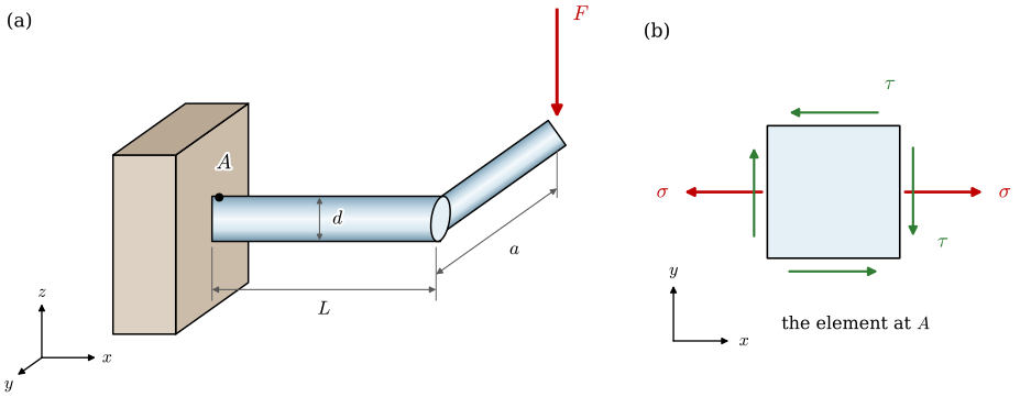
A steel shaft of diameter \(d = 30~\text{mm}\) is clamped at one end and carries a crank arm at the other, Figure 8.10.5. A force \(F = 1.5~\text{kN}\) acts at the end of the arm, perpendicular to the plane of shaft and arm. The arm is \(a = 300~\text{mm}\) long, measured from the shaft axis, and its plane lies \(L = 250~\text{mm}\) from the clamp. The shaft is made of the structural steel S355 with \(\sigma_\text{Y} = 355~\text{MPa}\). Determine the factor of safety against yielding by the Tresca and von Mises criteria, compare with the normal stress criterion, and find the diameter the shaft needs for a factor of safety of \(2\).
Figure 8.10.5: (a) A shaft clamped at one end, with a crank arm of length \(a\) at the distance \(L\) from the clamp and a force \(F\) at the end of the arm. (b) The stress element at the critical point \(A\) on top of the shaft at the clamp, seen from above, with the bending stress \(\sigma\) and the torsional shear stress \(\tau\).
Moving \(F\) to the shaft axis gives a transverse force \(F\) and a torque \(M_t = Fa\) about the axis. Every section of the shaft carries the torque, while the bending moment grows from zero at the arm to \(M = FL\) at the clamp, so the clamped section is the critical one. On that section the bending stress is largest at the top and the bottom, the torsional shear stress is largest all around the surface, and the top point \(A\) has both, with the bending stress in tension. The surface stresses of a solid circular section are derived later, in Chapter 8.16 and Chapter 8.13. 8.16.11 and 8.13.5, with the section moduli \(W = \pi d^3/32\) in bending and \(W = \pi d^3/16\) in torsion, give
The transverse force adds a shear stress that is zero at \(A\), and we leave it out. With \(x\) along the shaft as in Figure 8.10.5 (b), the state at \(A\) is plane stress with \(\sigma_x = \sigma\), \(\sigma_y = 0\) and a shear stress of magnitude \(\tau\), whose sign does not affect the criteria. 8.7.12 gives the principal stresses
The numbers follow with the moments \(M = FL\) and \(M_t = Fa\), in newtons and millimetres so that the stresses come out in megapascals. The normal stress criterion compares the largest principal stress \(\sigma_1\) with \(\sigma_\text{Y}\).
Code
F, L, a, d =1.5e3, 250, 300, 30# N, mm, mm, mmsigma_Y, n_req =355, 2# MPa, required factor of safetyM, M_t = F*L, F*a # N mmsigma =32*M/(np.pi*d**3)tau =16*M_t/(np.pi*d**3)sigma_1 = sigma/2+ np.sqrt((sigma/2)**2+ tau**2)sigma_T = np.sqrt(sigma**2+4*tau**2) # @eq-tresca-bending-torsionsigma_vM = np.sqrt(sigma**2+3*tau**2) # @eq-von-mises-bending-torsiond_T = (32*n_req/(np.pi*sigma_Y)*np.sqrt(M**2+ M_t**2))**(1/3) # @eq-shaft-diameterd_vM = (32*n_req/(np.pi*sigma_Y)*np.sqrt(M**2+0.75*M_t**2))**(1/3)ltx(r"\sigma &=", sigma, r"~\text{MPa}, \quad \tau =", tau, r"~\text{MPa}",r"\\\sigma_1 &=", sigma_1, r"~\text{MPa}, \quad n =", sigma_Y/sigma_1,r"\quad\text{(normal stress)}",r"\\\sigma_\text{T} &=", sigma_T, r"~\text{MPa}, \quad n =", sigma_Y/sigma_T,r"\quad\text{(Tresca)}",r"\\\sigma_\text{vM} &=", sigma_vM, r"~\text{MPa}, \quad n =", sigma_Y/sigma_vM,r"\quad\text{(von Mises)}",r"\\ d_\text{T} &=", d_T, r"~\text{mm}, \quad d_\text{vM} =", d_vM, r"~\text{mm}", aligned=True, precision=3)
\[ \begin{aligned}\sigma &=141.0~\text{MPa}, \quad \tau =84.9~\text{MPa}\\ \sigma_1 &=181.0~\text{MPa}, \quad n =1.96\quad\text{(normal stress)}\\ \sigma_\text{T} &=221.0~\text{MPa}, \quad n =1.61\quad\text{(Tresca)}\\ \sigma_\text{vM} &=204.0~\text{MPa}, \quad n =1.74\quad\text{(von Mises)}\\ d_\text{T} &=32.3~\text{mm}, \quad d_\text{vM} =31.4~\text{mm}\end{aligned} \]
The point \(A\) is elastic by all three criteria. Tresca gives a factor of safety of \(1.61\) and von Mises \(1.74\), the two differing by \(8~\%\), within the bound of 8.10.19. The normal stress criterion reports \(1.96\). It sees only \(\sigma_1 = 181~\text{MPa}\) and misses the part the shear stress plays in yielding. For this ductile shaft it is optimistic by \(13~\%\) against von Mises.
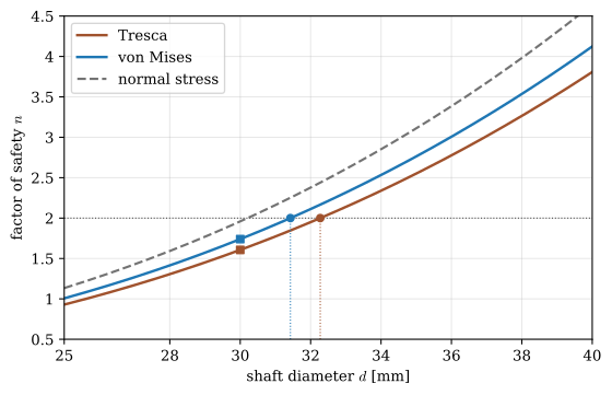
A factor of safety of \(2\) requires \(d = 32.3~\text{mm}\) by Tresca and \(31.4~\text{mm}\) by von Mises, and we would choose \(33~\text{mm}\) or \(32~\text{mm}\). The cube root in 8.10.22 shrinks the \(8~\%\) difference between the equivalent moments to under \(3~\%\) in diameter. Figure 8.10.6 checks the two diameters by plotting the factor of safety against the diameter for the three criteria.
Figure 8.10.6: The factor of safety at \(A\) against the shaft diameter. The squares mark the given shaft, \(d = 30~\text{mm}\), and the circles the diameters at which \(n = 2\), from 8.10.22. The factor of safety grows with \(d^3\).
Figure 8.8.9 follows the circle of point \(A\) as the torque grows: Tresca is reached at \(1.92\) times the working torque, the normal stress criterion only at \(3.24\) times it.
Example 2: A compressed-air receiver
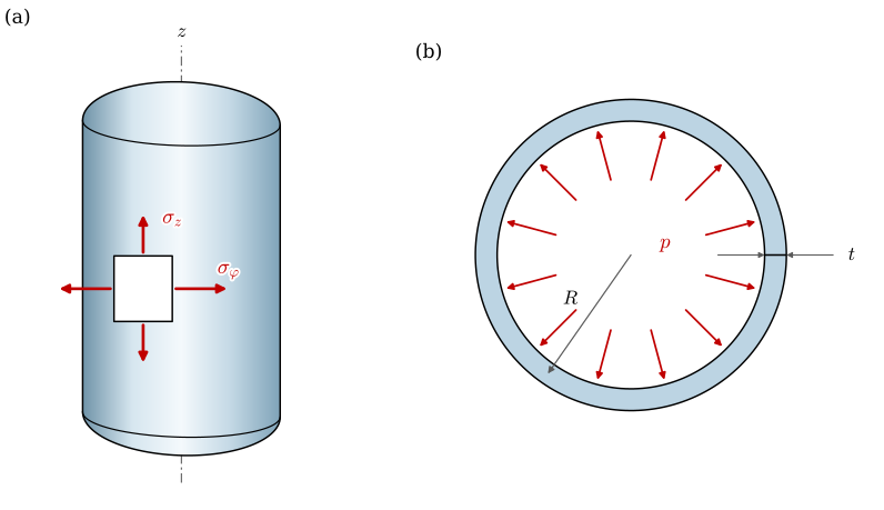
The receiver of an air compressor, Figure 8.10.7, is a closed cylinder of mean radius \(R = 300~\text{mm}\) and wall thickness \(t = 4~\text{mm}\), made of the pressure vessel steel P265GH with \(\sigma_\text{Y} = 265~\text{MPa}\). It works at the gauge pressure \(p = 1.0~\text{MPa}\), or \(10~\text{bar}\). Determine the factor of safety of the cylindrical wall against yielding by the Tresca and von Mises criteria, and the pressure at which the wall starts to yield by each.
Figure 8.10.7: (a) The air receiver, a closed cylinder with its axis \(z\) vertical, and an element of its wall with the hoop stress \(\sigma_\varphi\) and the axial stress \(\sigma_z\). (b) The cross-section, with the mean radius \(R\), the wall thickness \(t\), drawn much thicker than it is, and the internal pressure \(p\).
The wall is thin, \(t/R = 1/75\), so we take its stresses as uniform through the thickness and use the thin-walled cylinder of Example 4 in the chapter on normal stress, which gave the hoop and axial stresses
The third principal stress is the radial one, which goes from \(-p\) at the inner surface to \(0\) at the outer. At the outer surface the wall is therefore in plane stress with
The largest Mohr’s circle passes through the zero radial stress, so the largest shear stress acts on planes through the wall thickness and is twice the in-plane one, as Figure 8.8.4 shows. Tresca’s effective stress is \(\sigma_\text{T} = \sigma_1 - \sigma_3 = pR/t\), and 8.10.18 gives
The ratio of the two is \(2/\sqrt 3\), the largest possible by 8.10.19, since \(\sigma_z\) lies midway between \(\sigma_\varphi\) and \(0\). Setting each effective stress equal to \(\sigma_\text{Y}\) gives the pressure at which the wall starts to yield,
At the inner surface the radial stress adds \(\sigma_3 = -p\), and Tresca’s effective stress grows to \(pR/t + p\), by the fraction \(t/R\). We evaluate both surfaces.
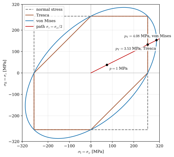
\[ \begin{aligned}\sigma_\varphi &=75.0~\text{MPa}, \quad \sigma_z =37.5~\text{MPa}\\ \text{outer:}\quad \sigma_\text{T} &=75.0~\text{MPa}, \quad n =3.53, \quad \sigma_\text{vM} =65.0~\text{MPa}, \quad n =4.08\\ \text{inner:}\quad \sigma_\text{T} &=76.0~\text{MPa}, \quad n =3.49, \quad \sigma_\text{vM} =65.8~\text{MPa}, \quad n =4.03\\ p_\text{Y} &=3.53~\text{MPa (Tresca)}, \quad p_\text{Y} =4.08~\text{MPa (von Mises)}\end{aligned} \]
At the working pressure the wall carries \(\sigma_\varphi = 75~\text{MPa}\) and \(\sigma_z = 37.5~\text{MPa}\), and the factor of safety against yielding is \(3.53\) by Tresca and \(4.08\) by von Mises. The wall starts to yield at \(3.53~\text{MPa}\) by Tresca and \(4.08~\text{MPa}\) by von Mises, the full \(15.5~\%\) apart. At the inner surface the radial stress lowers the factors of safety by about \(1~\%\), which confirms that the thin-wall model may neglect it.
Seen in the plane stress diagram of Figure 8.10.3, raising the pressure moves the stress point from the origin along the straight line \(\sigma_\text{II} = \sigma_\text{I}/2\), and yielding starts where that line leaves the hexagon or the ellipse. Figure 8.10.8 draws the line in megapascals and checks that the two crossings lie at the yield pressures of 8.10.23.
Figure 8.10.8: The loading path of the receiver wall in the plane stress diagram for \(\sigma_\text{Y} = 265~\text{MPa}\). The stress point moves out along \(\sigma_z = \sigma_\varphi/2\) as the pressure rises, and leaves the Tresca hexagon and the von Mises ellipse at the two yield pressures.
The working pressure is a quarter of the yield pressure by von Mises. A receiver is filled and emptied every time the compressor runs, and the margin also has to cover fatigue of the wall and its welds under those pressure cycles, Chapter 8.21, and the corrosion that thins the wall over the years.
Further reading
Hibbeler’s section on theories of failure covers the plane stress forms of the three criteria with many worked examples [8], and the chapter on static failure in Shigley adds the Coulomb-Mohr and modified Mohr criteria for brittle materials and design guidance for all of them [6]. In Swedish, Dahlberg treats the same effective stresses [9]. Dowling goes further into the octahedral shear stress view of von Mises and the experimental evidence for the criteria [1], and Ottosen and Ristinmaa develop yield surfaces, isotropic and anisotropic, as the first step of plasticity theory [10]. The tube experiments of Taylor and Quinney remain the classic test between Tresca and von Mises [5].
The Efficient Engineer’s video on failure theories goes through the same criteria with animated Mohr’s circles and yield surfaces, and adds the Coulomb-Mohr criterion for brittle materials [11].
References
[1]
Dowling NE. Mechanical behavior of materials: Engineering methods for deformation, fracture, and fatigue. 4th ed. Boston: Pearson; 2013.
[2]
Tresca H. Mémoire sur l’écoulement des corps solides soumis à de fortes pressions. Comptes Rendus de l’Académie Des Sciences 1864;59:754.
[3]
Mises R von. Mechanik der festen körper im plastisch-deformablen zustand. Nachrichten von Der Gesellschaft Der Wissenschaften Zu Göttingen, Mathematisch-Physikalische Klasse 1913:582–92.
Taylor GI, Quinney H. The plastic distortion of metals. Philosophical Transactions of the Royal Society of London Series A 1932;230:323–62. https://doi.org/10.1098/rsta.1932.0009.
Hill R. A theory of the yielding and plastic flow of anisotropic metals. Proceedings of the Royal Society of London Series A 1948;193:281–97. https://doi.org/10.1098/rspa.1948.0045.