10.9 Voltage dividers and analog input
The ESP32 can measure a voltage on a pin, but only between about 0 and 3 V. The car’s 3S LiPo battery gives up to 12.6 V, which would destroy the pin. Two resistors in series scale the battery voltage down to something the pin can take. This chapter builds that divider, and then does what the formula alone cannot: it measures the real divider and calibrates the reading against a known voltage. We end with a battery monitor that warns when the pack runs low and tells the motor code when to stop. The integrated car firmware uses its two source files unchanged.
The divider
Figure 10.9.1 shows the circuit: a resistor \(R_1\) from the battery to the midpoint, a resistor \(R_2\) from the midpoint to ground, and a voltmeter on the midpoint. Drag the Supply voltage slider and watch the midpoint follow it, always at the same fraction of the supply.
The same current flows through both resistors, so the battery voltage divides between them in proportion to their resistances (the voltage budget again). The midpoint voltage is
\[ V_\text{out} = V_\text{in}\,\frac{R_2}{R_1 + R_2}. \tag{10.9.1}\]
With \(R_1 = 33\) kΩ and \(R_2 = 10\) kΩ the fraction is \(10/43 = 0.233\), and a full battery at 12.6 V gives \(12.6 \cdot 0.233 = 2.93\) V at the midpoint, just inside the range of the pin. That is the design. Everything after this point is about the difference between the design and the circuit on the bench.
The real divider
The resistors in the kit are ±5 % parts (the gold band, see the series resistor). A “33 kΩ” resistor can be anything from 31.35 kΩ to 34.65 kΩ, and a “10 kΩ” one anything from 9.5 kΩ to 10.5 kΩ. Move the two lower sliders in Figure 10.9.1 to their ends and the midpoint at 12.6 V ranges from 2.71 V to 3.16 V. The upper value is beyond the range in which the ESP32 measures reliably, and the lower one would make every battery reading 7 % too low. Neither mistake shows up on paper.
The pin side is no better. The ESP32’s analog-to-digital converter has a gain that varies by several percent from chip to chip (The ESP32 ADC). So the chain from battery to number has two uncertain links, and we do not try to predict it. We measure it: first the resistors, then the midpoint with the multimeter, and finally the number the ESP32 reports at two known battery voltages. The last step is called calibration, and it absorbs every error of the chain at once.
Step 1: Measure the resistors
Measure both resistors with the ohmmeter before they go into the board, and log the values. Put the measured values into 10.9.1 and predict the midpoint at 12.00 V. If the 33 kΩ resistor reads 32.8 kΩ and the 10 kΩ one 10.06 kΩ, the prediction is \(12.00 \cdot 10.06/42.86 = 2.82\) V, against 2.79 V from the nominal values.
Step 2: Build on the bench supply
Build the divider on the breadboard and feed it from the lab supply at 12.00 V with a current limit of 10 mA (the divider draws 0.3 mA). The midpoint is not connected to the ESP32 yet.
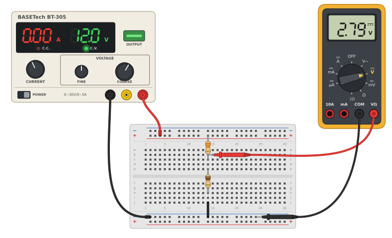
Measure the midpoint against the − rail and compare with the prediction from Step 1. The two should agree to within about 1 %, the accuracy of the ohmmeter and the voltmeter together.
The divider only protects the pin when the resistors are in the right places. Swap them, 10 kΩ on top and 33 kΩ to ground, and the same formula gives \(12.6 \cdot 33/43 = 9.67\) V on an input made for at most 3.3 V. The pin, or the whole chip, may not survive. So the midpoint is measured, at the highest voltage the battery can have, before its wire goes to the ESP32. It must read below 3.0 V at 12.6 V. Measure again after every change to the wiring.
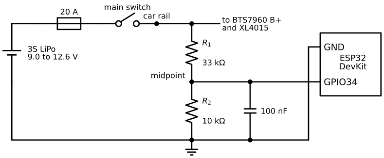
On the car the divider hangs on the car rail after the fuse and the main switch (Figure 10.9.3), so it is dead when the car is switched off and does not drain the battery on the shelf. It draws \(12.6/43\,000\) A = 0.29 mA when the car is on, which a 2200 mAh pack would need over 7000 hours to empty. The 100 nF capacitor in the figure keeps the reading steady; Loading of a divider explains why it is there.
Calibrating with two points
The ESP32 reports the midpoint as a whole number between 0 and 4095, its counts. Between the ends of its range the whole chain from battery voltage to counts is close to a straight line,
\[ V_\text{batt} = k N + b, \]
where \(N\) is the reading in counts, \(k\) the gain in volts per count and \(b\) the offset. A straight line is fixed by two points. We set the bench supply to two known voltages \(V_\text{lo}\) and \(V_\text{hi}\) (measured with the multimeter, not read off the supply’s display), read the counts \(N_\text{lo}\) and \(N_\text{hi}\), and solve for the two unknowns:
\[ k = \frac{V_\text{hi} - V_\text{lo}}{N_\text{hi} - N_\text{lo}}, \qquad V_\text{batt} = V_\text{lo} + k\,(N - N_\text{lo}). \tag{10.9.2}\]
As an example, suppose the monitor shows \(N_\text{lo} = 2680\) counts at 9.00 V and \(N_\text{hi} = 3745\) counts at 12.60 V. Then \(k = 3.60/1065 = 3.380\) mV per count, and a later reading of 3200 counts means \(V_\text{batt} = 9.00 + 0.003380\cdot(3200 - 2680) = 10.76\) V. The formula with nominal resistors and an ideal converter predicts \(k = (3.3/4095)\cdot(43/10) = 3.465\) mV per count, about 2.5 % more. Figure 10.9.4 shows how far apart the two lines are. Without calibration this board would report about 0.3 V too much at the cutoff and stop the car too late.
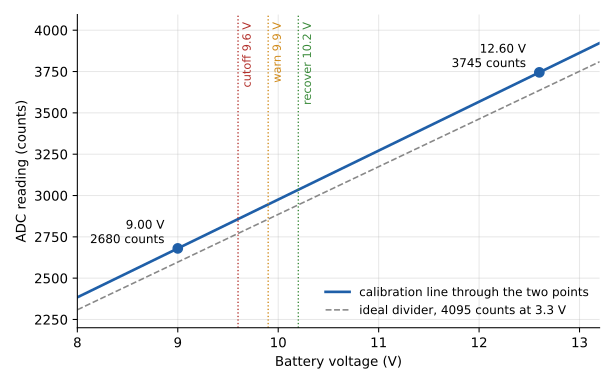
After calibrating, check a third voltage near the cutoff, e.g. 9.6 V. If the monitor is off by more than about 0.05 V there, move the upper calibration point down to 11.1 V, so that the line runs through the region where the decisions are made.
Build and calibrate the battery monitor
The battery monitor is a PlatformIO project in code/battery/ with three source files. battery.h and battery.cpp are the reusable part: they read the pin, filter, convert and decide the state. main.cpp is a small test program around them. The integrated car firmware copies battery.h and battery.cpp unchanged and adds the same build_flags.
The platformio.ini follows the PlatformIO chapter. The four calibration flags are commented out until we have measured them:
[env:esp32dev]
platform = espressif32@6.13.0
board = esp32dev
framework = arduino

upload_speed = 921600
monitor_speed = 115200
monitor_echo = yes
monitor_filters = send_on_enter, esp32_exception_decoder

build_flags =
    -D BAUD=${this.monitor_speed}
    -D BATT_PIN=34
    ; Two-point calibration: raw counts at two bench-supply voltages.
    ; Remove the ; in front of the four lines and put in your own numbers.
    ;-D BATT_ADC_LO=2597
    ;-D BATT_V_LO=9.0
    ;-D BATT_ADC_HI=3636
    ;-D BATT_V_HI=12.6
    -D BATT_WARN_V=9.9
    -D BATT_CUTOFF_V=9.6
    -D BATT_RECOVER_V=10.2
src/battery.h declares the interface and supplies a default for every optional flag:
// battery.h: 3S battery monitor through a voltage divider on an ADC1 pin.
//
// Required build flag: BATT_PIN.
// Optional build flags (defaults below):
//   BATT_ADC_LO, BATT_V_LO, BATT_ADC_HI, BATT_V_HI  two-point calibration
//   BATT_WARN_V, BATT_CUTOFF_V, BATT_RECOVER_V      state thresholds in volts
//   BATT_SAMPLE_MS, BATT_FILTER_N, BATT_TRIP_MS      filter and timing
//   BATT_CUTOFF_LATCH  1: CUTOFF holds until restart, 0: clears above RECOVER
#pragma once
#include <Arduino.h>

#if !defined(BATT_PIN)
#error "Set BATT_PIN under build_flags in platformio.ini"
#endif

// Without calibration flags the line comes from the ideal divider
// (33k over 10k) and an ideal ADC with 4095 counts at 3.3 V.
#if !defined(BATT_ADC_LO) || !defined(BATT_V_LO) || \
    !defined(BATT_ADC_HI) || !defined(BATT_V_HI)
#define BATT_UNCALIBRATED 1
#undef BATT_ADC_LO
#undef BATT_V_LO
#undef BATT_ADC_HI
#undef BATT_V_HI
#define BATT_ADC_LO 2597   // 9.0 V  -> 2.093 V at the pin
#define BATT_V_LO   9.0
#define BATT_ADC_HI 3636   // 12.6 V -> 2.930 V at the pin
#define BATT_V_HI   12.6
#endif

#ifndef BATT_WARN_V
#define BATT_WARN_V 9.9
#endif
#ifndef BATT_CUTOFF_V
#define BATT_CUTOFF_V 9.6
#endif
#ifndef BATT_RECOVER_V
#define BATT_RECOVER_V 10.2
#endif
#ifndef BATT_SAMPLE_MS
#define BATT_SAMPLE_MS 10   // one ADC reading every 10 ms
#endif
#ifndef BATT_FILTER_N
#define BATT_FILTER_N 32    // moving-average length, time constant N * SAMPLE_MS
#endif
#ifndef BATT_TRIP_MS
#define BATT_TRIP_MS 1000   // a low level must last this long to change state
#endif

#ifndef BATT_CUTOFF_LATCH
#define BATT_CUTOFF_LATCH 0
#endif

enum BattState { BATT_OK, BATT_WARN, BATT_CUTOFF };

void batteryBegin();               // call once in setup()
void batteryUpdate();              // call in every pass of loop()
float batteryRaw();                // filtered ADC counts
float batteryVolts();              // filtered battery voltage
BattState batteryState();          // OK, WARN or CUTOFF with hysteresis
const char* batteryStateName(BattState s);
float batteryCountsToVolts(float counts);
src/battery.cpp holds the implementation:
#include "battery.h"

static float filtered = 0;           // moving average of raw counts
static BattState state = BATT_OK;
static uint32_t lastSampleMs = 0;
static uint32_t lowSinceMs = 0;      // when the voltage first fell below a threshold
static bool low = false;

float batteryCountsToVolts(float counts) {
  const float gain = (BATT_V_HI - BATT_V_LO) / (float)(BATT_ADC_HI - BATT_ADC_LO);
  return BATT_V_LO + gain * (counts - BATT_ADC_LO);
}

static BattState levelOf(float v) {
  if (v < BATT_CUTOFF_V) return BATT_CUTOFF;
  if (v < BATT_WARN_V) return BATT_WARN;
  return BATT_OK;
}

void batteryBegin() {
  analogReadResolution(12);                     // 0..4095
  analogSetPinAttenuation(BATT_PIN, ADC_11db);  // widest input range
  long sum = 0;
  for (int i = 0; i < BATT_FILTER_N; i++) sum += analogRead(BATT_PIN);
  filtered = (float)sum / BATT_FILTER_N;
  state = levelOf(batteryVolts());              // no delay at start-up
  lastSampleMs = millis();
}

void batteryUpdate() {
  uint32_t now = millis();
  if (now - lastSampleMs < BATT_SAMPLE_MS) return;
  lastSampleMs = now;

  // Exponential moving average over about BATT_FILTER_N samples
  filtered += (analogRead(BATT_PIN) - filtered) / BATT_FILTER_N;
  float v = batteryVolts();

  // Going down: the lower level must persist for BATT_TRIP_MS
  BattState level = levelOf(v);
  if (level > state) {
    if (!low) { low = true; lowSinceMs = now; }
    if (now - lowSinceMs >= BATT_TRIP_MS) { state = level; low = false; }
  } else {
    low = false;
  }

  // Going up: only once the voltage is clearly back
  if (state == BATT_CUTOFF && BATT_CUTOFF_LATCH) return;
  if (state != BATT_OK && v > BATT_RECOVER_V) state = BATT_OK;
}

float batteryRaw() { return filtered; }

float batteryVolts() { return batteryCountsToVolts(filtered); }

BattState batteryState() { return state; }

const char* batteryStateName(BattState s) {
  switch (s) {
    case BATT_OK:   return "OK";
    case BATT_WARN: return "WARN";
    default:        return "CUTOFF";
  }
}
and src/main.cpp prints the result every 500 ms and accepts two commands, raw and cal:
#include <Arduino.h>
#include "battery.h"

// BAUD and BATT_PIN come from build_flags in platformio.ini
#if !defined(BAUD) || !defined(BATT_PIN)
#error "Set BAUD and BATT_PIN under build_flags in platformio.ini"
#endif

bool rawMode = false;        // toggled by typing "raw" in the monitor
uint32_t lastPrintMs = 0;

void printCalibration() {
  Serial.printf("Calibration: %.1f counts = %.2f V, %.1f counts = %.2f V%s\n",
                (double)BATT_ADC_LO, (double)BATT_V_LO,
                (double)BATT_ADC_HI, (double)BATT_V_HI,
#ifdef BATT_UNCALIBRATED
                "  (UNCALIBRATED, ideal divider)");
#else
                "");
#endif
  Serial.printf("Thresholds: warn %.2f V, cutoff %.2f V, recover %.2f V\n",
                (double)BATT_WARN_V, (double)BATT_CUTOFF_V, (double)BATT_RECOVER_V);
}

void readCommand() {
  if (!Serial.available()) return;
  String cmd = Serial.readStringUntil('\n');
  cmd.trim();
  if (cmd == "raw") {
    rawMode = !rawMode;
    Serial.println(rawMode ? "raw mode on" : "raw mode off");
  } else if (cmd == "cal") {
    printCalibration();
  } else if (cmd.length() > 0) {
    Serial.println("commands: raw (toggle raw mode), cal (show calibration)");
  }
}

void setup() {
  Serial.begin(BAUD);
  batteryBegin();
  Serial.printf("Battery monitor on GPIO %d\n", BATT_PIN);
  printCalibration();
}

void loop() {
  batteryUpdate();
  readCommand();

  if (millis() - lastPrintMs < 500) return;
  lastPrintMs = millis();

  if (rawMode) {
    // Fresh block average for calibration: 256 readings, no filter history
    uint32_t sum = 0;
    for (int i = 0; i < 256; i++) sum += analogRead(BATT_PIN);
    Serial.printf("raw %.1f\n", sum / 256.0f);
  } else {
    Serial.printf("raw %6.1f   %5.2f V   %s\n", batteryRaw(), batteryVolts(),
                  batteryStateName(batteryState()));
  }
}
Calibrate on the bench, with the divider that will go into the car and the ESP32 that will read it. The ESP32 is powered from USB during calibration and nothing is connected to its VIN pin.
- Build the divider on the breadboard: 33 kΩ from the supply input to the midpoint, 10 kΩ from the midpoint to ground, 100 nF from the midpoint to ground. Leave the midpoint wire loose.
- Set the bench supply to 12.6 V with a current limit of 50 mA and connect it to the divider. Measure the midpoint with the multimeter: about 2.9 V. Do not continue otherwise.
- Connect the supply’s negative terminal to an ESP32 GND pin and the midpoint to GPIO 34.
- Upload the project and open the serial monitor. Type
rawand press Enter. The monitor now prints the average of 256 readings every 500 ms. - Set the supply to 9.00 V, checked with the multimeter at the divider input. Wait for the numbers to settle and note the reading as
BATT_ADC_LO. - Set the supply to 12.60 V and note the reading as
BATT_ADC_HI. - Remove the
;in front of the four calibration lines inplatformio.ini, enter the two readings (BATT_V_LO=9.0,BATT_V_HI=12.6stay) and upload again. Typecalto check that the values arrived; the wordUNCALIBRATEDmust be gone. - Set the supply to 9.6, 9.9 and 11.1 V in turn and compare the printed voltage with the multimeter. They should agree within 0.05 V.
- Turn the supply slowly down from 11 V to 9.4 V and back up. The state should change to
WARNbelow 9.9 V and toCUTOFFbelow 9.6 V, each about one second after the voltage crossed the level, and return toOKonly above 10.2 V.
The normal output looks like this as the voltage falls through the warning level, with the example calibration. WARN appears one second after the voltage went below 9.90 V:
raw 2950.1    9.91 V   OK
raw 2946.4    9.90 V   OK
raw 2943.2    9.89 V   OK
raw 2941.0    9.88 V   OK
raw 2939.5    9.88 V   WARN
The calibration belongs to that ESP32 and that pair of resistors. If either is replaced, the calibration must be repeated. In the car, the divider is wired as in Figure 10.9.3, and the bench supply connects to the car rail in place of the battery when we want to check the calibration again.
How the monitor works
The ESP32 ADC
analogRead(pin) starts a conversion and returns a whole number. The ESP32’s ADC has 12 bits, so the result lies between 0 and \(2^{12} - 1 = 4095\). Internally the converter compares the input with a reference of about 1.1 V, and the median value is 1.1 V with a spread from 1.0 to 1.2 V between chips (ESP-IDF v4.4 ADC documentation). To measure larger voltages, an attenuator in front of the converter scales the input down. Arduino-ESP32 core 2.0.17 uses the strongest setting, ADC_11db, by default; we set it explicitly anyway with analogSetPinAttenuation(pin, ADC_11db) so the code does not depend on the default. (ESP-IDF 5 calls the same setting ADC_ATTEN_DB_12, which is closer to its true value.)
What range does 11 dB give? Espressif’s documents answer differently depending on how much error they accept. The ESP32 datasheet (v5.3, Table 4-4) gives an effective measurement range of 150 to 2450 mV, with a total error of ±60 mV after factory calibration, and adds that accuracy is worse for readings above about 3000 counts, i.e. about 2450 mV. The Arduino-ESP32 documentation lists 150 to 3100 mV as the measurable range for the same setting. Both are right: the converter responds up to about 3.1 V, but its characteristic bends near both ends. Below about 0.15 V the reading stays at or near 0, and toward the top it flattens and reaches 4095 before the input reaches 3.3 V. A pot turned to its stops therefore does not give a clean 0 and 4095, and code reading a throttle should treat the last few percent at each end as “fully on” and a small band around the middle as zero.
Between the ends the response is close to a straight line, but its slope and offset differ from chip to chip by up to about 6 % according to the datasheet. The function analogReadMilliVolts(pin) corrects for this using calibration values Espressif burned into each chip at the factory and returns millivolts at the pin. For the battery we go one step further and calibrate the complete chain, divider resistors included, against a bench supply, as described in Calibrating with two points.
The ESP32 has two converters. ADC1 serves GPIO 32 to 39. ADC2 serves several other pins (GPIO 0, 2, 4, 12 to 15 and 25 to 27) and is shared with the Wi-Fi radio: while Wi-Fi is running, a read from ADC2 fails. The car runs a Wi-Fi access point, so every analog input on the car uses ADC1. GPIO 34 to 39 are also input-only: they have no output driver and no internal pull-up or pull-down resistors. That makes them poor choices for anything else and good choices for analog inputs, which is why the pin map puts the battery on GPIO 34, the bench pot on GPIO 35 and the motor current sense on GPIO 36 and 39.
Loading of a divider
10.9.1 assumed that nothing draws current from the tap. Anything connected there, a multimeter, an ADC pin, a careless wire, appears as a load resistance \(R_L\) in parallel with \(R_2\), and the output drops to
\[ V_\text{out} = V_\text{in}\,\frac{R_2 \parallel R_L}{R_1 + R_2 \parallel R_L}, \qquad R_2 \parallel R_L = \frac{R_2 R_L}{R_2 + R_L}. \]
A convenient way to judge how much a load matters is to replace the divider by its Thévenin equivalent: an ideal source of the unloaded voltage \(V_\text{in} R_2/(R_1+R_2)\) behind the resistance \(R_\text{th} = R_1 \parallel R_2\). A load current \(I_L\) then lowers the output by \(I_L R_\text{th}\). The ESP32 input leaks at most 50 nA (datasheet Table 5-3), so its steady error is \(50\ \text{nA}\cdot R_\text{th}\), negligible for any \(R_\text{th}\) below a few hundred kΩ.
The ADC is not a steady load, though. At each conversion it connects a small sampling capacitor to the pin and charges it from the source. Through a large \(R_\text{th}\) that charge arrives slowly, the conversion sees a voltage that has not settled, and the reading comes out low and noisy. A high-resistance node also picks up interference more easily, and on the car there is a lot of it: the motor driver switches 10 A or more at 20 kHz a few centimetres away.
The remedy is a capacitor of about 100 nF from the tap to ground, close to the pin. It holds the voltage while the sampling capacitor draws its charge, and together with \(R_\text{th}\) it forms a low-pass filter that removes switching noise. Espressif specifies the ADC’s linearity with exactly such a 100 nF capacitor on the input (datasheet Table 4-3). The filter’s time constant \(\tau = R_\text{th} C\) must stay short compared with how fast the measured voltage changes, which for a battery is easy.
Choosing the resistances is therefore a compromise. Small resistors give a stiff, quiet node but draw current from the battery all the time and heat themselves. Large resistors save the battery but make the node soft. For a battery divider read a few times per second, a total of a few tens of kΩ with a 100 nF capacitor works well on the car, where the 3S pack holds thousands of mAh. A small battery that must last for weeks, like the remote’s, justifies a few hundred kΩ.
The potentiometer as an adjustable divider
A potentiometer is a resistive track with a terminal at each end and a sliding contact, the wiper, that touches the track somewhere between them. The resistance between the two end terminals is fixed, e.g. \(R = 10\) kΩ. The wiper splits the track into two parts that always add up to \(R\): a part \(R - R_b\) above the wiper and a part \(R_b\) below it. With the ends on 3.3 V and ground, the pot is a divider whose ratio we set by hand,
\[ V_\text{wiper} = 3.3\ \text{V}\cdot\frac{R_b}{R}. \]
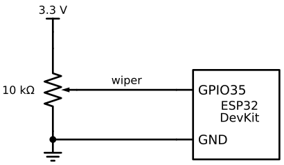
On a linear pot \(R_b\) is proportional to the rotation angle, so the wiper voltage is too. The thumb joysticks in the kit contain two such pots, one per axis, held at the middle by a spring. At rest each axis sits near \(1.65\) V, and the reading moves up or down from there. The bench throttle in the labs is a pot on THROTTLE_POT_PIN (GPIO 35), wired as in Figure 10.9.5.
The value of the pot matters little for the ratio, but it sets the current and the source resistance seen by the pin. A 10 kΩ pot across 3.3 V draws \(3.3/10\,000 = 0.33\) mA. The resistance seen from the wiper is the two parts of the track in parallel, largest at mid-travel where it is \(R/4 = 2.5\) kΩ. A 100 Ω pot would draw 33 mA from the 3.3 V regulator for no benefit, and a 1 MΩ pot would make the pin sensitive to the loading and noise discussed below.
Before the pot touches the board, we check it as in the multimeter chapter: the resistance between the outer pins is about 10 kΩ, and with the outer pins on a 3.3 V bench supply the wiper voltage moves from near 0 to near 3.3 V. Only then does the wiper go to GPIO 35.
Filtering the readings
Successive readings of a steady voltage scatter by several counts, and on the car the motor adds its own disturbance. The datasheet’s advice is to sample several times and filter or average (notes to datasheet Table 4-3). batteryUpdate() is meant to be called in every pass of loop(), but it takes a reading only every BATT_SAMPLE_MS (10 ms), so the filter behaves the same however fast the loop runs. Each new reading \(x\) updates the filtered value \(y\) by
\[ y \leftarrow y + \frac{x - y}{N}, \]
an exponential moving average with \(N\) = BATT_FILTER_N = 32. Every reading moves the average a thirty-second of the way toward itself, which smooths the noise like an average of about 32 readings while needing one stored number. The time constant is about \(N \cdot 10\ \text{ms} = 0.32\) s, short enough to follow a battery and long enough to ignore a single bad sample. batteryBegin() seeds the filter with a plain average of 32 readings, so the first printed value is already correct.
The raw command in main.cpp uses a different method: it averages 256 fresh readings each time it prints. Averaging \(n\) independent readings reduces random noise by a factor \(\sqrt{n}\), here 16, and the result does not depend on what the filter saw before. That is what we want while turning the supply knob during calibration.
The low-voltage cutoff with hysteresis
A LiPo cell is damaged if it is discharged too far. We warn at 9.9 V (3.3 V per cell) and cut off at 9.6 V (3.2 V per cell). These are voltages under load. The pack has internal resistance, so the voltage at its terminals sags while the motor draws current and recovers when it stops. With, e.g., 30 mΩ for the pack and its wiring and 15 A drawn by the motor, the sag is \(0.030 \cdot 15 = 0.45\) V. A half-empty pack can therefore dip below 9.6 V on a hard acceleration and read 10.5 V a second later.
A single threshold would make the state flicker every time the voltage hovers around it, and the car would stutter. batteryUpdate() avoids this in two ways. A lower state is entered only when the filtered voltage has stayed below its threshold for BATT_TRIP_MS (1000 ms), so a short dip during acceleration does not trigger it. A higher state is entered only above BATT_RECOVER_V (10.2 V, 3.4 V per cell), well above the level that caused the change. The gap between the level that enters a state and the level that leaves it is called hysteresis. Between 9.6 and 10.2 V the state depends on where the voltage came from: a pack falling from full is still OK at 10.0 V, while a pack that has already given a warning stays in WARN at 10.0 V.
After a cutoff the motor stops, the sag disappears and the rest voltage may well climb above 10.2 V, which ends the cutoff and lets the car drive into the next one. Setting -D BATT_CUTOFF_LATCH=1 makes CUTOFF permanent until the ESP32 restarts, which is the safer choice for the car once it drives on its own battery. What to do in each state, limit the throttle in WARN and stop the motor in CUTOFF, belongs to the motor code; the monitor only reports.
Defaults and build flags
battery.h uses #ifndef to give each optional flag a default, so a project only sets what it needs. When any of the four calibration flags is missing, the header falls back to the ideal chain, 2597 counts at 9.0 V and 3636 counts at 12.6 V, and defines BATT_UNCALIBRATED. main.cpp prints this at start-up and on cal, so an uncalibrated monitor cannot go unnoticed. The calibration readings may have decimals (e.g. -D BATT_ADC_LO=2680.4), since the averaged raw output has one.
The 1S divider on the XIAO remote
The hand-held remote runs on a XIAO ESP32-S3 powered by a single LiPo cell, 4.20 V when full. The ESP32-S3 measures 0 to about 3.1 V at 11 dB attenuation (ESP-IDF v4.4, ESP32-S3), so the cell also needs a divider, and the XIAO has no built-in one on the standard board. With \(R_1 = R_2 = 200\) kΩ the ratio is exactly one half:
\[ V_\text{pin}(4.20\ \text{V}) = 2.10\ \text{V}, \qquad V_\text{pin}(3.70\ \text{V}) = 1.85\ \text{V}, \qquad V_\text{pin}(3.30\ \text{V}) = 1.65\ \text{V}. \]
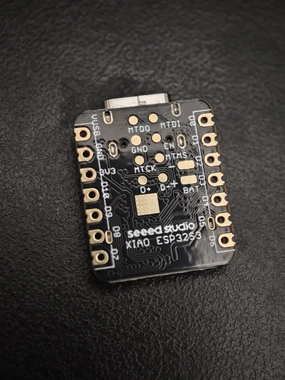
BAT, − and +, at the right.
The resistors are large on purpose. The divider is soldered to the battery pad (Figure 10.9.6) and draws \(4.2/400\,000 = 10.5\ \mu\)A whenever a cell is connected, which empties a 400 mAh cell only after several years. The price is a Thévenin resistance of \(200 \parallel 200 = 100\) kΩ, more than ten times that of the car’s divider, so the 100 nF capacitor at the pin matters even more here (\(\tau = 10\) ms). The midpoint goes to A0 (labelled D0 on the board, GPIO 1).
Calibration follows the same two-point method with 3.30 and 4.20 V from the bench supply, before the divider is soldered to the XIAO. The XIAO’s built-in charger drives the battery pad whenever USB is connected, and it would fight the bench supply if the divider were already attached. Never set the supply above 4.20 V. Once in place, the reading shows close to 4.2 V while the cell is charging, whatever its real state. The XIAO chapter covers the board itself.
Exercises
- In the Falstad circuit simulator, build a 12.6 V source, 33 kΩ from it to a node, and 10 kΩ from the node to ground. Read the node voltage. Then add a load resistor from the node to ground and lower it from 1 MΩ to 10 kΩ. At what load resistance has the node voltage dropped by 1 %? Compare with the Thévenin estimate \(R_L \approx 99\, R_\text{th}\).
- Redesign the 3S divider with \(R_1 = 47\) kΩ and \(R_2 = 10\) kΩ. Compute the pin voltage at 12.6 V and at 9.6 V, the current and the Thévenin resistance. Which property of the ADC does this design avoid, and what does it give up?
- A group calibrates and gets 2702 counts at 9.00 V and 3790 counts at 12.60 V. Compute \(k\) and \(b\), and the counts at which the warning and the cutoff should trip. Put the numbers into
platformio.iniand confirm withcal. - The Wokwi potentiometer project reads a potentiometer with
analogRead(). Turn the knob to both stops and note the readings. Then write a function that turns the reading of a spring-centred joystick axis into a throttle between \(-1\) and \(1\), with a dead band of ±100 counts around the measured centre and full throttle a little before each end of the travel.