A bolted joint can be taken apart; a permanent joint cannot, without destroying it. A weld melts the parts together, an adhesive bonds them, and a rivet is deformed so that it cannot be pulled out. Each carries the load through a small region, the weld, the glue line or the rivet shank, and the design question is the same for all three: what stress does the load set up there, and how large must the region be?
For welds, the chapter derives the stresses in a fillet weld from a free body and arrives at the method of EN 1993-1-8 that European engineers use to size welds. For adhesives, it derives the shear-lag model, which explains why a longer overlap stops helping. Rivets build on the bolted joints loaded in shear. When the force on each weld of a part is not obvious, a finite element model finds it, as the chapter Sizing welds with SolidWorks Simulation shows.
Welding processes
Most welding is fusion welding: the edges of the parts melt, usually with a filler metal, and solidify into one piece. Oxygen and nitrogen from the air would make the weld porous and brittle, so the melt is shielded, and the processes differ in where the heat comes from and how the melt is shielded. Each has a reference number in ISO 4063[1], which drawings and welding procedures use instead of the name.
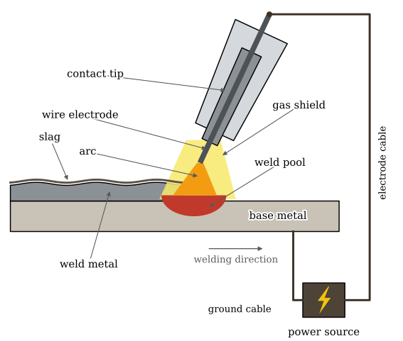
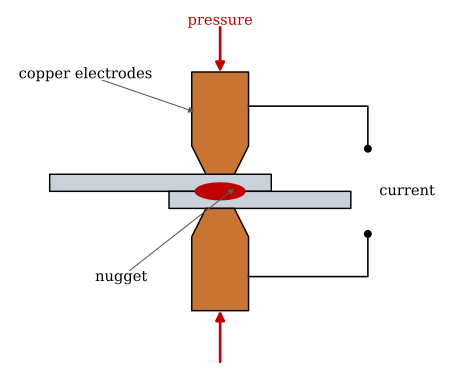
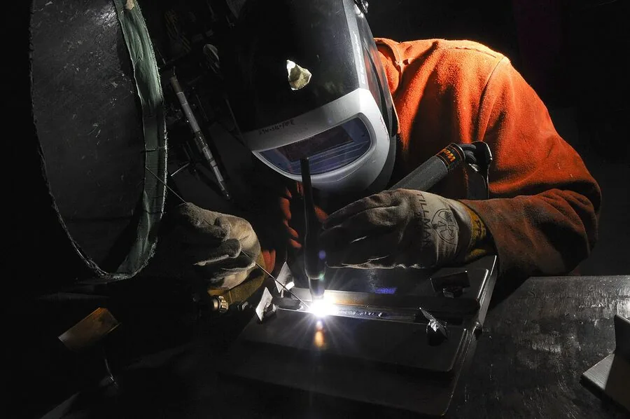
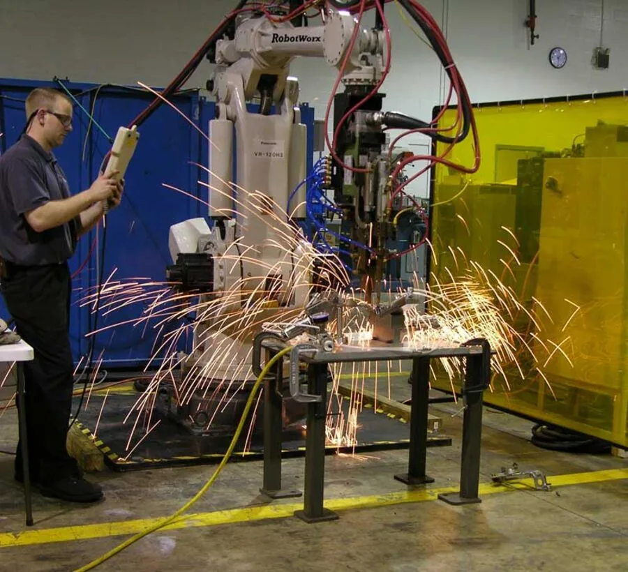
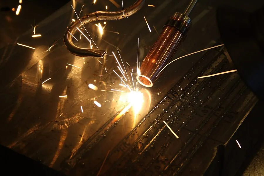
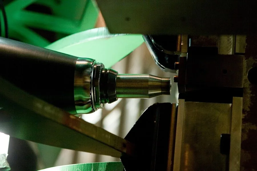
In arc welding (Figure 9.16.1), an electric arc between the electrode and the work melts both into a weld pool, which a gas shield protects and which solidifies into weld metal behind the torch. In resistance spot welding (Figure 9.16.2), a current through two pressed sheets melts a lens of metal, the nugget, where the sheets touch.
Figure 9.16.1: Arc welding in principle: the wire electrode, fed through the contact tip of the torch, melts in the arc into the weld pool under a gas shield; the power source closes the circuit through the work.
Figure 9.16.2: Resistance spot welding in principle: copper electrodes press the sheets together, and the current melts a nugget at the interface.
Stick welding (MMA) · 111
A flux-coated electrode melts into the weld; the coating gives off gas and slag that shield the melt. Simple and portable, it works outdoors and on site.
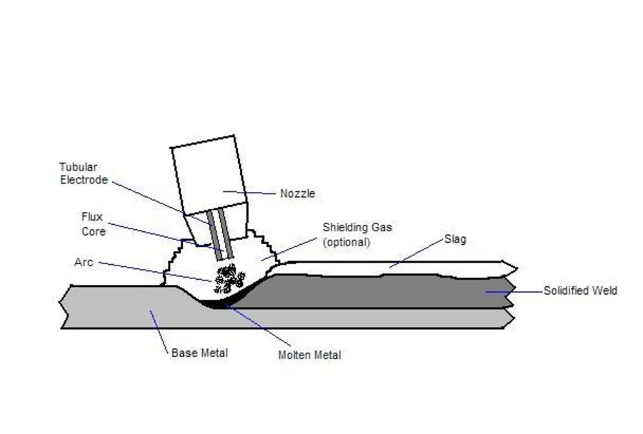
Flux-cored wire · 114, 136
A tubular wire with flux inside, fed continuously, with a shielding gas (136) or without (114). Fast, for thick steel and outdoor work.
MIG and MAG · 131, 135
A wire fed through the torch melts into the weld under a gas shield: inert argon for aluminium (MIG), argon with carbon dioxide for steel (MAG). The workshop process.
TIG · 141
A tungsten electrode that does not melt, an inert gas, and a filler rod added by hand. Slow and clean: thin sheet, stainless steel, aluminium.
Resistance spot welding · 21
Two electrodes press the sheets together, and a short, large current melts a lens of metal between them. No filler, no gas: car bodies.
Laser beam welding · 52
A focused beam melts a narrow, deep weld at high speed with little heat in the part. Automated production lines.
Friction stir welding · 43
A rotating tool softens and stirs the metal of both parts together without melting it. Aluminium panels, also aluminium to steel.
Explosion welding · 441
An explosive drives one plate onto another so fast that they bond in the solid state, with a wavy interface. Cladding steel with another metal.
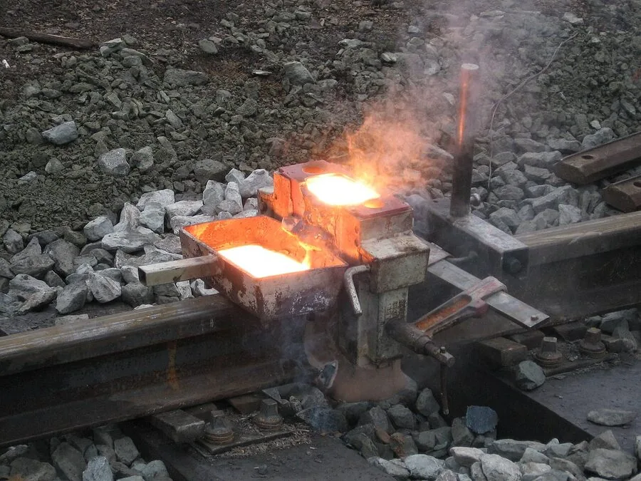
Thermite welding · 71
Aluminium powder reduces iron oxide, and the molten steel it makes runs into a mould between two rail ends. Rails on the track.
Weld joints and the flow of force
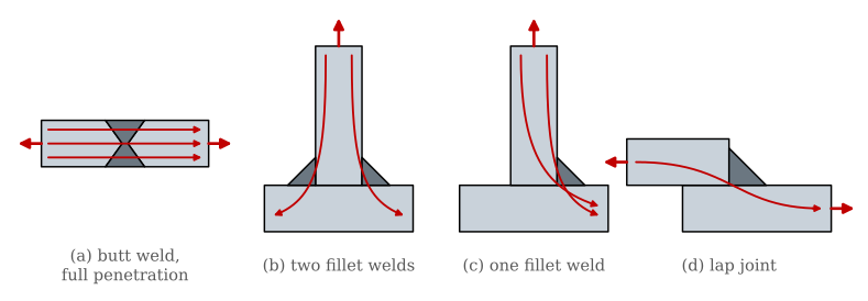
A butt weldsv. stumsvets fills a gap between two edges; a fillet weldsv. kälsvets is a triangle of weld metal in a corner. In a butt weld with full penetration (Figure 9.16.3 a) the weld is part of the section and the force passes straight through, but the edges must be prepared and the welder must reach the root, so it is the expensive joint. Fillet welds need no preparation and are by far the most common, but the force has to turn the corner, from the stem through the weld into the plate. Where it turns, at the root and the toe of the weld, the stress concentrates, which makes fillet welds weaker in fatigue than butt welds. A single fillet (c) also passes the force off-centre and bends the weld about its root.
Figure 9.16.3: The force flow through (a) a double-sided butt weld with full penetration, (b) a double fillet weld, (c) a single fillet weld and (d) a fillet-welded lap joint, after the lecture slides.
The weld symbol
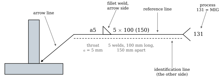
A drawing shows a weld by a symbol standardized in ISO 2553[2] (Figure 9.16.4). The arrow line points at the joint, and the reference line carries the description. A symbol on the solid reference line means the weld lies on the side the arrow touches, the arrow side; on the dashed identification line, the other side. The triangle is a fillet weld. To its left stands the size: a5 is a throat thicknesssv. a-mått of 5 mm, the height of the weld triangle measured from its root, while z5 would give the leg \(z = \sqrt{2}\,a\).
Throat\(a\) = the height of the weld triangle, a5 = 5 mm; leg\(z = \sqrt{2}\,a\)
To its right stands the length: 5 × 100 (150) is five welds of 100 mm, 150 mm apart; a continuous weld leaves it out. The tail carries the ISO 4063 process number, 131 for MIG.
Figure 9.16.4: The weld symbol of ISO 2553: a fillet weld with the throat \(a = 5\) mm on the arrow side, five welds 100 mm long, made by process 131.
Stresses in a fillet weld
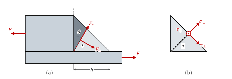
What stress does a fillet weld carry? Take the transverse fillet weld of Figure 9.16.5 a, which joins the end of an upper plate to a lower plate, the plates pulled apart by the force \(F\) along a weld of length \(L\). The weld is a triangle with two legs of length \(h\). Following Budynas and Nisbett in their Section 9-2 [3], we cut the weld through its root at the angle \(\theta\) from the vertical leg and take the part of the weld between the cut and the upper plate as a free body. The upper plate pulls it with \(F\), so the cut must push back with a normal force \(F_n\) and a shear force \(F_s\) along the cut,
\[
F_s = F\sin\theta, \qquad F_n = F\cos\theta
\]
The cut runs from the root to the weld face. The face is the line where the distances along the two legs add up to \(h\), so a cut of length \(t\) at the angle \(\theta\) reaches it when \(t(\sin\theta + \cos\theta) = h\). On the cut area \(tL\) the nominal stresses are therefore
and the von Mises stress of the two is \(\sigma' = \sqrt{\sigma^2 + 3\tau^2}\).
Figure 9.16.5: (a) A transverse fillet weld of leg \(h\) cut through its root at the angle \(\theta\): the normal force \(F_n\) and the shear force \(F_s\) on the cut balance the force \(F\) from the upper plate. After Budynas and Nisbett, Fig. 9-9. (b) The throat plane at \(45^\circ\), of height \(a\), with the normal stress \(\sigma_\perp\), the shear stress \(\tau_\perp\) across the weld and the shear stress \(\tau_\parallel\) along it, out of the page.
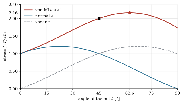
Which cut is the critical one? The code below evaluates 9.16.1 over all angles.
Code
th = np.linspace(0, np.pi/2, 9001)sig_hL = np.cos(th)**2+ np.sin(th)*np.cos(th) # sigma in units of F/(h L)tau_hL = np.sin(th)**2+ np.sin(th)*np.cos(th) # tau in units of F/(h L)vm_hL = np.sqrt(sig_hL**2+3*tau_hL**2)i_vm, i_tau, i_45 = vm_hL.argmax(), tau_hL.argmax(), np.argmin(abs(th - np.pi/4))
Figure 9.16.6: The stresses on a cut through a transverse fillet weld at the angle \(\theta\), in units of \(F/(hL)\). The von Mises stress peaks at \(62.6^\circ\); the throat at \(45^\circ\) is the plane the standards use.
The largest von Mises stress, \(2.16\,F/(hL)\), acts on a cut at about \(62.5^\circ\), not on the \(45^\circ\) throat, where it is \(2.00\,F/(hL)\), 8 % lower. This is the result Budynas and Nisbett report, and they add the warning that matters most: photoelastic and finite element studies show stress concentrations at the root and the toe that no such nominal stress captures, and “we have no analytical approach that predicts the existing stresses” [3]. Weld design therefore does not try to find the true stress. It agrees on a simple nominal stress on a fixed plane and calibrates the allowed value against tests of real welds.
The directional method of EN 1993-1-8
European design takes the stresses on the throat, the \(45^\circ\) plane of height \(a\) in Figure 9.16.5 b, with the area \(A_w = \sum aL\). The force per unit length of weld is resolved into the normal stress \(\sigma_\perp\) on the throat, the shear stress \(\tau_\perp\) across the weld and the shear stress \(\tau_\parallel\) along it. According to Section 4.5.3.2 of EN 1993-1-8[4], the weld is strong enough if
The left-hand side of the first is the von Mises stress on the throat. \(R_m\) is the ultimate tensile strength of the weaker joined part, which the standard writes \(f_u\). The partial safety factor \(\gamma_{M2}\) is 1.25, as recommended in the standard’s Table 2.1, and the correlation factor\(\beta_w\) calibrates the criterion to tests: 0.8 for S235, 0.85 for S275, 0.9 for S355 and 1.0 for S420 and S460 (its Table 4.1). Weld metal is stronger than the parent metal, and the stronger the steel, the less of that margin remains; \(\beta_w\) expresses this. The cut at \(62.5^\circ\) and the stress concentrations are inside the calibration, not ignored by it.
according to Section 4.5.3.3 of the standard, which writes \(f_{vw,d}\) for \(\tau_w\). A throat in pure shear passes 9.16.2 when \(\sqrt{3}\,\tau \le R_m/(\beta_w\gamma_{M2})\), so the simplified method treats every weld as if loaded along its length, the worst direction. It is safe and needs no resolution of stresses.
Sizing the throat in the simplest case
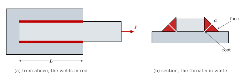
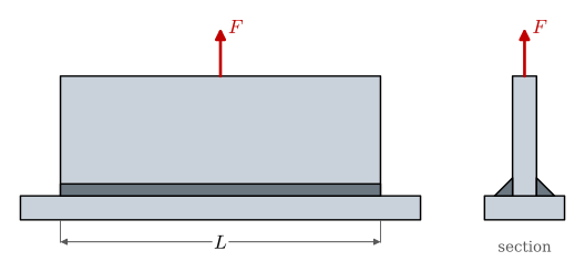
The simplest weld to size is a bar lapped onto a plate and welded along both edges, pulled along the welds (Figure 9.16.7). The two welds share the force over the throat area \(A = 2aL\), and the only stress is the shear along them,
\[
\tau_\parallel = \frac{F}{2aL}
\tag{9.16.4}\]
Figure 9.16.7: The simplest weld to size: a bar lapped onto a plate and fillet welded along both edges over the length \(L\), pulled along the welds by \(F\). (a) From above; (b) the section, with the throat \(a\) from the root to the face of each weld.
The throat follows from whichever allowed shear stress we trust. With an allowed shear stress \(\tau_\text{allow}\) and a factor of safety \(\eta\), \(\tau_\parallel \le \tau_\text{allow}/\eta\) gives
\[
a \ge \frac{F\eta}{2L\,\tau_\text{allow}}
\tag{9.16.5}\]
The directional method, 9.16.2, is von Mises applied to the ultimate strength: pure shear passes when \(\sqrt{3}\,\tau_\parallel \le R_m/(\beta_w\gamma_{M2})\), which is 9.16.5 with \(\tau_\text{allow} = R_m/(\sqrt{3}\,\beta_w) \approx 0.6\,R_m/\beta_w\) and \(\eta = \gamma_{M2}\),
\[
a \ge \frac{\sqrt{3}\,\beta_w\,\gamma_{M2}\,F}{2L\,R_m}
\tag{9.16.6}\]
A cruder and safer route takes Tresca and the yield strength instead: in pure shear Tresca allows \(\tau = 0.5\,R_e\), and 9.16.5 becomes
\[
a \ge \frac{F\eta}{L\,R_e}
\tag{9.16.7}\]
It is conservative twice over, since Tresca allows 13 % less shear than von Mises and the yield strength lies well below the ultimate strength, and it needs no table. Example 1 compares the two.
Along the welds:\(\tau_\parallel = F/(2aL)\)\(\;\Rightarrow\;\)\(a \ge \sqrt{3}\,\beta_w\gamma_{M2}F/(2LR_m)\)\(\quad\) or, conservatively, \(a \ge F\eta/(LR_e)\)
Example 1: A lug loaded along its welds
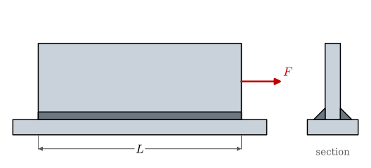
A lug of S355 steel, \(L = 80\) mm long and 10 mm thick, is fillet welded on both sides to a base plate and carries \(F = 120\) kN along the welds (Figure 9.16.8). Find the throat with the directional method, and with Tresca on the yield strength for the same factor of safety. For S355, \(R_m = 510\) MPa, \(R_e = 355\) MPa and \(\beta_w = 0.9\); \(\gamma_{M2} = 1.25\).
Figure 9.16.8: Example 1: a lug welded to a base plate with a fillet weld on each side, loaded along the welds.
This is the case of Figure 9.16.7, standing up: 9.16.6 and 9.16.7 apply directly. The welds are taken as full size from end to end; otherwise EN 1993-1-8 deducts \(2a\) from each length.
Code
R_m, beta_w, gamma_M2 =510.0, 0.9, 1.25# S355 [MPa]F_lug, L_lug, t_lug =120e3, 80.0, 10.0# [N], [mm], [mm]s_allow = R_m/(beta_w*gamma_M2) # right-hand side of the first condition [MPa]a_ex1 = np.sqrt(3)*F_lug/(2*L_lug*s_allow) # @eq-pj-a-directional [mm]R_e =355.0# yield strength of S355 [MPa]a_tresca = F_lug*gamma_M2/(L_lug*R_e) # @eq-pj-a-tresca, eta = gamma_M2 [mm]
The two routes give
\[ \begin{aligned}\frac{R_m}{\beta_w\gamma_{M2}} &=453.0~\text{MPa}\\\text{directional:}\quad a &\ge2.87~\text{mm}\\\text{Tresca, yield:}\quad a &\ge5.28~\text{mm}\end{aligned} \]
The directional method asks for 2.87 mm, and we choose \(a = 3\) mm, also the smallest throat the standard allows: a3 on both sides of the lug. Tresca on the yield strength asks for 5.28 mm, a6, nearly twice as much weld metal for the same load. It is a safe estimate when the standard is not at hand, and a wasteful one when it is.
EN 1993-1-8 (Sections 4.5.1 and 4.5.2) adds two rules of detail. The throat must be at least 3 mm, and a weld shorter than 30 mm or six throats, whichever is longer, should not be designed to carry load. Such a weld still carries whatever reaches it, but its start and end, where the arc strikes and stops, are not full size, and a short weld is mostly start and end.
Never less than\(a = 3\) mm, and never count on a weld shorter than 30 mm or \(6a\)
Example 2: The lug pulled off the plate
The lug of Example 1 is now pulled straight up by the same 120 kN, across its welds (Figure 9.16.9). Find the throat with both methods.
Figure 9.16.9: Example 2: the lug of Example 1 pulled off the base plate, across its welds.
Each weld carries \(f = F/(2L)\) per unit length across its axis. On the \(45^\circ\) throat this splits into equal normal and shear parts, \(\sigma_\perp = \tau_\perp = f/(\sqrt{2}\,a)\), so the von Mises stress of 9.16.2 is \(2\sigma_\perp = \sqrt{2}\,f/a\). The simplified method needs no resolution: \(f \le \tau_w a\).
Code
f_line = F_lug/(2*L_lug) # force per unit length of each weld [N/mm]a_dir = np.sqrt(2)*f_line/s_allow # sqrt(2) f/a = s_allowa_sig = f_line/(np.sqrt(2)*0.9*R_m/gamma_M2) # second condition: sigma_perp <= 0.9 R_m/gammatau_w = R_m/(np.sqrt(3)*beta_w*gamma_M2) # @eq-pj-simplified [MPa]a_simp = f_line/tau_w
The two methods give
\[ \begin{aligned}\text{directional:}\quad a &\ge2.34~\text{mm}~(\text{first condition}),\quad a \ge1.44~\text{mm}~(\text{second})\\\text{simplified:}\quad \tau_w &=262.0~\text{MPa},\quad a \ge2.87~\text{mm}\end{aligned} \]
A fillet weld is stronger loaded across than along: on the throat a transverse force is half normal stress, which the von Mises criterion weighs less than shear. The simplified method gives 2.87 mm in both examples, 23 % more here. Both round up to the 3 mm minimum.
A fillet weld is stronger across its axis than along it
For the throat \(a\), the directional stress \(\sqrt{2}\,f/a\) is \(2f/h\) in the leg \(h = \sqrt{2}\,a\): exactly the \(45^\circ\) value of Figure 9.16.6. The standard uses the plane that the free body puts 8 % short of the worst, and \(\beta_w\) covers the difference.
Example 3: The lug in bending
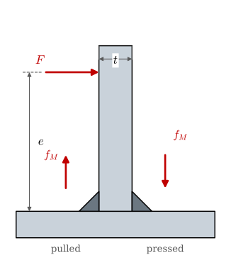
The same lug is pushed sideways by \(F = 10\) kN at \(e = 100\) mm above the plate, normal to its face (Figure 9.16.10). Find the throat.
Figure 9.16.10: Example 3: the lug in section, pushed sideways by \(F\) at the height \(e\). The moment \(Fe\) is carried as a couple by the two welds, the left one pulled and the right one pressed.
The welds carry the shear \(F\) and the moment \(Fe\). The moment is a couple of the two welds with the lug thickness \(t\) as lever arm, a little shorter than the true distance between the throats and so on the safe side: each weld carries \(f_M = Fe/(tL)\) per unit length, the left one pulled up, the right one pressed down. The shear adds \(f_V = F/(2L)\) to each, horizontally, towards the lug’s push. On the pulled weld both forces lie in the plane of the section, and the throat runs from the root at \(45^\circ\) away from the lug, with its normal pointing up and towards the lug. Resolving the forces on it gives \(\sigma_\perp = (f_M + f_V)/(\sqrt{2}\,a)\) and \(\tau_\perp = (f_M - f_V)/(\sqrt{2}\,a)\).
Code
F_b, e_b =10e3, 100.0# [N], [mm]f_M = F_b*e_b/(t_lug*L_lug) # the couple, per unit length [N/mm]f_V = F_b/(2*L_lug) # the shear, per unit length [N/mm]# directional method on the pulled weld: sigma_perp and tau_perp times a; the throat normal# is (1, 1)/sqrt(2) and the force on the weld (f_V, f_M)s_a, t_a = (f_M + f_V)/np.sqrt(2), (f_M - f_V)/np.sqrt(2)a_b_dir = np.sqrt(s_a**2+3*t_a**2)/s_allowa_b_simp = np.hypot(f_M, f_V)/tau_w # simplified method, the resultant
The forces per unit length and the throats are
\[ \begin{aligned}f_M &=1.25 \cdot 10^{3}~\text{N/mm},\quad f_V =62.5~\text{N/mm}\\\text{directional:}\quad a &\ge3.81~\text{mm},\qquad \text{simplified:}\quad a \ge4.78~\text{mm}\end{aligned} \]
A twelfth of the load of Examples 1 and 2 needs a thicker weld: a4 by the directional method, a5 by the simplified one. The lever arm of 100 mm against a lug 10 mm thick multiplies the force on the welds by twenty, and the shear hardly matters. A lug loaded sideways is better welded along a longer foot, braced with a gusset, or turned so the load acts in its plane.
Bending is the worst load for a weld: weld both sides, keep the load in the plane of the part
TipIn industry: who decides that a weld is good enough
The throat on the drawing is half of a weld’s strength; the other half is whether the welder made it. A load-bearing steel structure in Europe is made to EN 1090-2 [5], which sorts structures into four execution classes, EXC1 to EXC4, by the consequences of failure, the loading and the complexity of the fabrication; where no class is specified, EXC2 applies, and the requirements on quality, testing and acceptance grow with the class [6]. In practice this means a written welding procedure for each joint, qualified by tests, welders certified for the process and position, and an inspection plan that sets how much of the welding is checked by eye and how much by ultrasound or radiography. A fillet weld that looks right can lack fusion at the root, and the inspection is there to find it. When the forces on the welds of a part are not as obvious as on the lugs above, they are found with a finite element model and weld connectors, as in Sizing welds with SolidWorks Simulation.
Adhesive joints
An adhesive jointsv. limförband carries the load through a thin layer of glue over the whole overlap. It joins materials that cannot be welded to each other, adds no heat, seals the joint and spreads the load instead of concentrating it. A modern car body contains many metres of bonded seams, alone or combined with spot welds and rivets. Adhesives are sorted by how they cure:
Curing
Examples
Typical use
without air, in contact with metal (anaerobic)
thread lockers, retaining compounds
securing screws, fixing bearings on shafts
by heat
one-component epoxies
car bodies, cured in the paint oven
by moisture in the air
cyanoacrylate, polyurethane, silicone
small parts, glazing, sealing
as a film or tape
epoxy films, structural tapes
aircraft panels, mounting
by evaporation of a solvent
contact adhesives
large flexible surfaces
by mixing two components
epoxy, acrylic, polyurethane
structural bonding
Glue is strong in shear, weak in peel
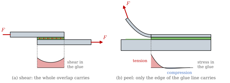
Whatever the adhesive, a bonded joint is strong in shear and weak in peel (Figure 9.16.11). In shear the whole overlap carries the load. In peel the glue line is pulled open from one edge like a strip of tape, and only a narrow band at that edge carries it, so the joint fails at a fraction of the load. Joints are therefore made as laps, so the load runs along the glue line, and the question is how the shear spreads over the overlap.
Figure 9.16.11: A bonded joint (a) in shear, where the whole overlap carries the load, and (b) in peel, where the glue line opens from the edge and the tension in the glue is concentrated in a narrow band there, followed by a little compression.
The shear-lag model
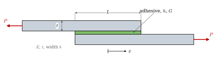
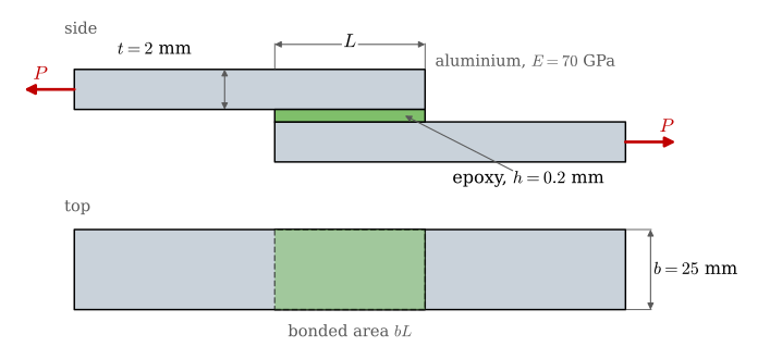
Dividing the force by the bonded area, \(\tau = P/(bL)\) for a lap of width \(b\) and length \(L\), predicts that a twice as long overlap carries twice the load. Tests show it does not. The reason, found by Volkersen in 1938, is the elasticity of the adherends [3]. Take the single lap joint of Figure 9.16.12: two equal adherends of thickness \(t\) and modulus \(E\), bonded over the length \(L\) by an adhesive layer of thickness \(h\) and shear modulus \(G\), pulled by \(P\). Measure \(x\) from the middle of the overlap, and let \(N_1(x)\) and \(N_2(x)\) be the forces per unit width in the upper and the lower adherend.
Figure 9.16.12: The single lap joint of the shear-lag model: adherends of thickness \(t\), modulus \(E\) and width \(b\), an adhesive layer of thickness \(h\) and shear modulus \(G\) over the overlap \(L\). The adhesive is drawn far thicker than it is.
The adhesive pulls on each adherend with the shear stress \(\tau\), so the upper adherend gains force at the rate \(\mathrm{d}N_1/\mathrm{d}x = \tau\) and the lower one loses it, \(\mathrm{d}N_2/\mathrm{d}x = -\tau\), with \(N_1 + N_2 = P/b\). The adhesive is sheared by the difference of the displacements of the two adherends, \(\tau = G(u_1 - u_2)/h\), and each adherend stretches with its own force, \(\mathrm{d}u_i/\mathrm{d}x = N_i/(Et)\). Differentiating twice,
For equal adherends the shear is symmetric, \(\tau = A\cosh\omega x\), and it must add up to the load, \(b\int_{-L/2}^{L/2}\tau\,\mathrm{d}x = P\). That fixes \(A\):
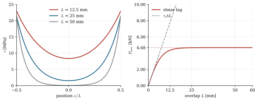
The shear is lowest in the middle and highest at the ends, where the strains of the adherends differ most. If the adhesive fails when \(\tau_\max\) reaches its strength \(\tau_a\), the joint carries
which approaches \(2b\tau_a/\omega\) and does not grow beyond it. The model neglects that a single lap bends, because the two forces are offset by the adherend thickness. The bending adds a peel stress at the ends of the glue line, as Goland and Reissner showed in 1944, which makes the ends worse still.
Example 4: How long an overlap?
Two aluminium strips, \(t = 2\) mm thick and \(b = 25\) mm wide, \(E = 70\) GPa, are bonded in a single lap with an epoxy layer of \(h = 0.2\) mm (Figure 9.16.13). Take \(G = 1\) GPa and a shear strength \(\tau_a = 25\) MPa for the epoxy, values assumed for the example. How much load does the joint carry with the 12.5 mm overlap of the standard lap-shear specimen of ISO 4587[7,8], and with 25 and 50 mm? What does \(\tau_a bL\) predict?
Figure 9.16.13: Example 4: two aluminium strips bonded in a single lap over the overlap \(L\), seen from the side (the glue line drawn thick) and from above.
\(\omega = 0.267\) mm\(^{-1}\), so \(1/\omega = 3.7\) mm.
overlap \(L\) [mm]
\(\tau_\max/\tau_\text{avg}\)
\(P_\max\), shear lag [kN]
\(\tau_a bL\) [kN]
12.5
1.79
4.36
7.81
25
3.35
4.67
15.62
50
6.68
4.68
31.25
Figure 9.16.14: Example 4. Left: the shear stress along the overlap from the shear-lag model, for three overlap lengths at the same load of 4 kN. Right: the load the joint carries against the overlap length, from the shear-lag model and from the average stress.
The standard overlap of 12.5 mm already carries 93 % of what any overlap can. Doubling it adds 7 %, and from 25 to 50 mm it adds nothing, while the average stress promises four times as much. The shear concentrates within a few times \(1/\omega\), here about 4 mm, of the ends. A stronger joint needs a larger \(1/\omega\), by 9.16.8 a thicker or softer glue line or stiffer adherends, or a wider joint.
A longer overlap stops helping beyond a few times \(1/\omega\); a wider joint always helps
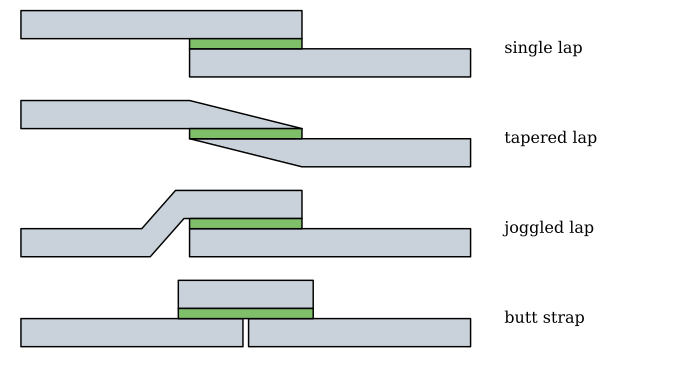
The joint shapes of Figure 9.16.15 follow from the same model. Tapered ends make the adherends softer where the shear peaks, so their strains match better there. A joggle brings the adherends into line and removes most of the bending that causes peel. A strap over a butt joint keeps the load path straight.
Figure 9.16.15: Four bonded joints, after the lecture slides: a single lap, a lap with tapered ends, a joggled lap, and a butt joint with a strap.
Rivets
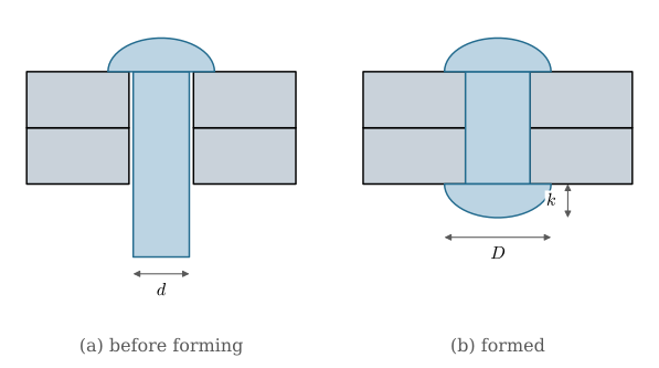
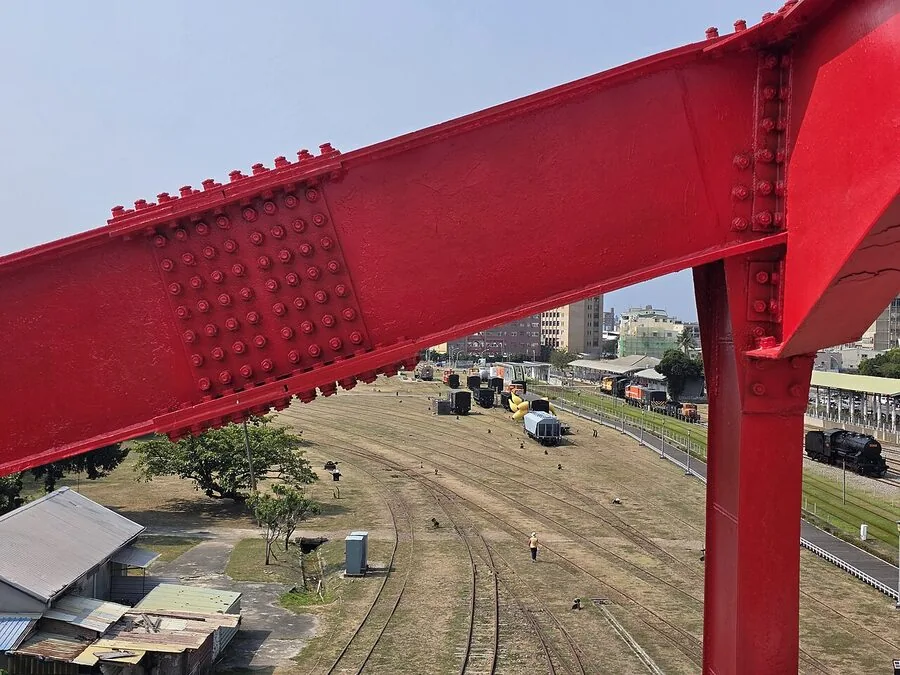
A rivetsv. nit is a pin with a head, put through holes in the parts and deformed at its other end into a second head. A solid rivet is formed by hammering or pressing its tail (Figure 9.16.16) and needs access to both sides of the joint. Hot-driven steel rivets held together the bridges and ships of the nineteenth century (Figure 9.16.18); they shrink as they cool and clamp the plates, and the shank swells to fill the hole. Welding and preloaded bolts have replaced them in steel structures, but solid aluminium rivets still join the skins of aircraft. The video of Figure 9.16.17 shows solid rivets being set by hand, hot and cold.
Figure 9.16.16: A solid rivet in section: (a) put through the holes, the tail standing out; (b) the tail formed into a second head of diameter \(D\) and height \(k\), the shank swollen to fill the holes.
Figure 9.16.17: This Video is 28.74x More Riveting, by Alec Steele: solid rivets set by hand, from the point in the video where the riveting starts.
Figure 9.16.18: A riveted steel girder at a railway yard: the rows of round heads are rivets.
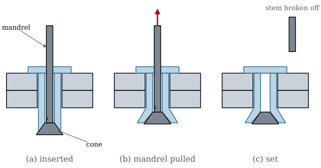
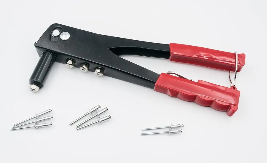
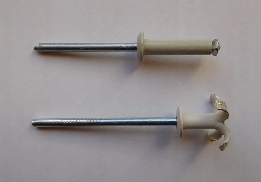
A blind rivetsv. blindnit (popnit) is set from one side only (Figure 9.16.19). A hollow rivet on a mandrel is put through the holes, and a hand tool (Figure 9.16.20) pulls the mandrel until its head expands the rivet’s far end and the mandrel breaks off at a notch. Blind rivets join sheet metal, boxes and brackets, and printed parts to metal.
Figure 9.16.19: Setting a blind rivet: (a) the rivet with its mandrel put through the holes; (b) the tool pulls the mandrel, whose head expands the far end of the rivet; (c) the mandrel breaks at its notch and its head stays in the rivet.
(a) A hand riveter with blind rivets.
(b) Blind rivets before (above) and after setting (below).
Figure 9.16.20: Blind rivets and the tool that sets them.
Dimensioning rivets
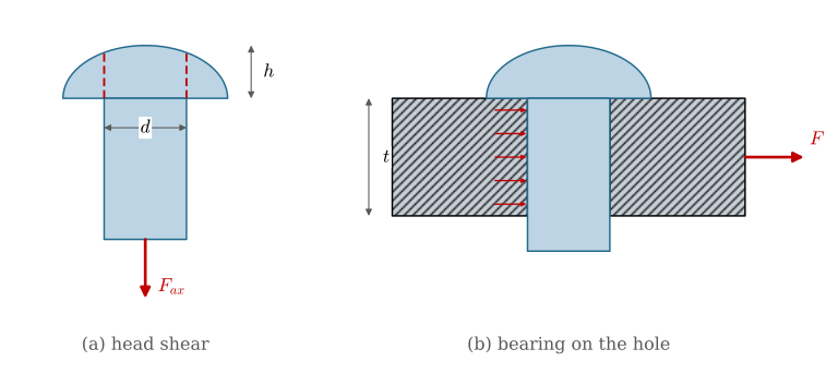
Riveted joints in structures are designed to standards, but a rivet of our own design is checked for three failures (Figure 9.16.21). The shank shears across, over its area \(\pi d^2/4\); an axial force strips the head off, shearing the cylinder of diameter \(d\) and height \(h\) where the shank meets it; and the shank presses on the hole wall, the bearing pressure taken over the projected area \(dt\) of the thinnest plate. With the shear strengths \(\tau_b\) of the shank and \(\tau_s\) of the head and the allowed bearing pressure \(p_h\), each reduced by a factor of safety,
\[
F \le \frac{\tau_b\,\pi d^2}{4}, \qquad F_{ax} \le \tau_s\,\pi d h, \qquad F \le p_h\,d\,t
\tag{9.16.11}\]
Figure 9.16.21: Two of the checks of a rivet: (a) an axial force \(F_{ax}\) shears the head of height \(h\) off round the shank of diameter \(d\) (dashed); (b) the shank presses on the hole wall of the plate of thickness \(t\).
Shear\(F \le \tau_b\pi d^2/4\)\(\quad\)Head\(F_{ax} \le \tau_s\pi d h\)\(\quad\)Bearing\(F \le p_h d t\)
Table 9.16.1: Typical ultimate shear strengths of rivet materials. The range covers the alloys and tempers; the maker’s value for the rivet at hand replaces it.
Rivet material
Shear strength [MPa]
steel
280 to 600
aluminium
60 to 180
copper
160 to 200
brass
220 to 400
Blind rivets are rated by their makers, who give a shear and a tensile load per rivet; those values replace the first two checks. For steel rivets in steel structures, Table 3.4 of EN 1993-1-8 [4] gives the shear resistance per shear plane as
with the ultimate strength \(R_{m,r}\) of the rivet and the area \(A_0\) of the hole, which a driven rivet fills; 0.6 is close to the \(1/\sqrt{3}\) of the welds. The plate also fails as in a bolted joint, by tearing out to its edge or breaking across the holes (Figure 9.10.21), which edge distances of about three hole diameters prevent. The standard also asks that riveted joints carry shear, not tension, and that a single rivet is never used in a single lap joint (Section 3.6.1): the offset of the plates bends the rivet and tilts its heads.
Rivets carry shear, not tension, and never one rivet alone in a single lap
The rivets of a long row do not share the load equally, for the same reason as the glue line of 9.16.8: the plates stretch between the rivets, and the outer rivets, where the strains of the plates differ most, carry the most. A riveted lap is a shear-lag joint with the glue gathered into points, and rows of more than a few rivets along the load gain little.
Example 5: A riveted lap joint
Two plates of S235 steel (\(R_m = 360\) MPa), \(t = 4\) mm thick, are riveted in a lap joint that carries 20 kN. The steel rivets fill holes of \(d_0 = 6\) mm, and the rivet steel has \(R_{m,r} = 400\) MPa. The rivets are spaced so that the bearing resistance reaches its full value, \(F_{b,Rd} = 2.5\,R_m\,d_0\,t/\gamma_{M2}\) (Table 3.4 of EN 1993-1-8). How many rivets are needed?
Shear governs by a factor of three: four rivets, two by two so that none stands alone. A strap on each side of a butt joint puts the rivets in double shear, doubles their capacity and removes the bending of the single lap.
Problems
Problem 1: A lug loaded at an angle. The lug of Example 1 carries its 120 kN at \(45^\circ\) between along and across the welds. Find the throat with the directional method.
Answer:Each weld carries \(f = F/(2L) = 750\) N/mm, 530 N/mm along and 530 N/mm across. Then \(\tau_\parallel = 530/a\) and \(\sigma_\perp = \tau_\perp = 530/(\sqrt{2}a) = 375/a\), and 9.16.2 gives \(\sqrt{4 \cdot 375^2 + 3 \cdot 530^2}/a \le 453\) MPa, so \(a \ge 2.62\) mm. With the 3 mm minimum, \(a = 3\) mm.
Problem 2: Weld on one side only. The lug of Example 2 is welded on one side only. Why is this a poor idea even with a thicker weld?
Answer:The force passes beside the weld, as in Figure 9.16.3 c, and bends it about its root. The root opens in tension, the weakest direction of a fillet weld. The SolidWorks chapter shows the required throat growing eightfold when a weld is made single-sided.
Problem 3: A longer foot. How long must the lug of Example 3 be for a3 welds to carry the sideways load?
Answer:With the shear neglected, \(f_M = Fe/(tL)\) and the directional method on the pulled weld gives \(\sqrt{2}\,f_M/a \le 453\) MPa, so \(L \ge \sqrt{2}\,Fe/(t\,a \cdot 453) = 104\) mm with \(a = 3\) mm. A foot of about 110 mm, allowing for the shear.
Problem 4: A thicker glue line. The joint of Example 4 is bonded with \(h = 0.4\) mm instead of 0.2 mm. What happens to \(1/\omega\) and to the load the 12.5 mm overlap carries?
Answer:\(\omega^2 \propto 1/h\), so \(\omega\) drops by \(\sqrt{2}\) to 0.189 mm\(^{-1}\) and \(1/\omega\) grows to 5.3 mm. 9.16.10 gives 5.5 kN instead of 4.4 kN, and the upper limit grows from 4.7 to 6.6 kN. In practice adhesives are weaker in thick layers, so the gain is smaller.
Problem 5: A butt strap. The plates of Example 5 are placed end to end and joined with a 4 mm strap on each side. How many rivets are needed on each side of the joint?
Answer:Each rivet shears in two planes and carries \(2 \cdot 5.43 = 10.9\) kN, so \(20/10.9 = 1.8\): two rivets on each side, four in all.
Further reading
Budynas and Nisbett [3] treat welded and bonded joints, including weld groups in torsion and bending and the peel models of bonded laps. EN 1993-1-8 [4] is the reference for welds and rivets in steel. The chapter on fatigue treats welded details under cyclic load, where the stress at the toe decides.
EN 1090-2 Execution of steel structures and aluminium structures – Part 2: Technical requirements for steel structures. Brussels, Belgium: European Committee for Standardization; n.d.