10.4 The series resistor
In the first experiment the lab supply kept the LED alive by limiting the current. A battery, a USB charger or an ESP32 pin has no such limit. This chapter adds the part that limits the current in every LED circuit we will ever build, a resistor in series with the LED, and shows how to choose its value. It follows Ben Eater’s second video.
The voltage budget
Suppose the supply gives 5 V and the LED should run at about 1.9 V and 20 mA. The two cannot simply be connected: 5 V across the LED would drive an enormous current. Ben draws the solution as a budget. Going once around the loop, from the + of the supply through the parts and back to its −, the voltages across the parts add up to the voltage of the supply. This is Kirchhoff’s voltage law, and it holds in every closed loop. If the LED takes 1.9 V of the 5 V, the remaining 3.1 V must be taken by something else, and that something is a resistor:
\[ 5~\text{V} = \underbrace{3.1~\text{V}}_{\text{resistor}} + \underbrace{1.9~\text{V}}_{\text{LED}}. \]
A resistor obeys Ohm’s law: the voltage across it is its resistance \(R\) times the current \(I\) through it,
\[ U = RI. \tag{10.4.1}\]
In a single loop the same current flows through every part, so the resistor carries the 20 mA of the LED. Solved for \(R\), 10.4.1 gives the resistor that takes 3.1 V at 20 mA:
\[ R = \frac{U}{I} = \frac{5 - 1.9}{0.020}~\Omega = 155~\Omega. \]
That is the whole design. In general, for a supply voltage \(U_s\), an LED forward voltage \(U_f\) and a wanted current \(I\),
\[ R = \frac{U_s - U_f}{I}. \tag{10.4.2}\]
Resistors are sold in a fixed set of standard values, so 155 Ω does not exist. The kit has 150 Ω and 220 Ω. We take the larger one, which gives a little less current than planned and keeps the LED on the safe side, exactly as Ben does. With 220 Ω the current becomes
\[ I = \frac{5 - 1.9}{220}~\text{A} = 0.014~\text{A} = 14~\text{mA}. \]
Write this prediction in the log before building anything.
Step 1: Find and measure the resistor
A through-hole resistor carries its value as coloured bands. The first two bands are digits, the third is the number of zeros to add, and a gold fourth band means ±5 % tolerance. Red-red-brown is 2, 2 and one zero, 220 Ω.
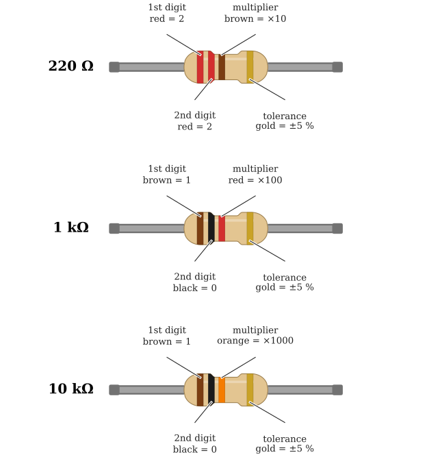
Colours are easy to misread under lab lighting, so we measure every resistor before it goes into a circuit. Set the meter to Ω, red lead in VΩ, and touch the probes to the two legs while holding the resistor by one leg only (fingers on both legs add the resistance of the body in parallel). A 220 Ω resistor with 5 % tolerance reads between 209 Ω and 231 Ω. Write the measured value in the log; we use it below.
The resistor datasheet gives two more numbers that matter.1 The power rating of the common small through-hole resistor is 0.25 W, the heat it can get rid of without damage. The tolerance is the ±5 % we just checked.
Step 2: Build
Set the supply to 0 V with a current limit of 30 mA, twice the predicted current. Place the resistor so that one leg shares a column with the long leg of the LED, and connect the red lead to the column of the other leg. The black lead goes to the short leg, as before.
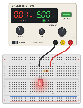
0.01 on its display, and stays in C.V. mode.
Trace the path of the current with a finger before switching on: from the red lead, through the resistor, into the LED at the long leg, out at the short leg, and back to the black lead. Every step of the path must go through a part; two legs in the same column only connect.
Step 3: Measure at 5 V
Switch on and raise the voltage to 5.00 V. The LED lights, the C.V. lamp stays on, and the current display shows 0.01, which is all a display with 10 mA steps can say about 14 mA. It confirms that the current is in the right range and that nothing is shorted. The exact milliamperes follow in the next chapter, where we measure them with the multimeter.
Step 4: Turn the voltage up and down
Now repeat the experiment that destroyed Ben’s first LED. Turn the voltage from 2 V to 7 V in steps of 1 V and log the current display at each step. With 10 mA steps on the display, the predicted 14.1 mA reads 0.01 and the 23.2 mA reads 0.02.
| Voltage (V) | Predicted (mA) | Display (A) |
|---|---|---|
| 2 | 0.5 | |
| 3 | 5.0 | |
| 4 | 9.5 | |
| 5 | 14.1 | |
| 6 | 18.6 | |
| 7 | 23.2 |
The predictions use 10.4.2 with \(U_f = 1.9~\text{V}\) and \(R = 220~\Omega\). The current now grows steadily, about 4.5 mA per volt, and a volt more or less makes little difference. The resistor has made the circuit robust. In the video, from 8:30, Ben does the same and the LED brightness hardly changes at all.
We stop at 7 V because the LED’s absolute maximum is 30 mA and the current would reach it at about 8.5 V. If the voltage is turned further by mistake, the supply’s 30 mA limit still catches it: the C.C. lamp lights and the current stops rising. Keep both safety nets, the resistor and the current limit, until the circuit is known to work.
Figure 10.4.3 is the same circuit in Falstad. It has one slider for the supply voltage and one for the resistance, and voltmeters across the resistor and the LED show the voltage budget at work: the two readings always add up to the supply voltage.
Step 5: A larger resistor
Switch off and change one thing: replace the 220 Ω resistor by a 1 kΩ one (brown-black-red, measured first). The prediction at 5 V is
\[ I = \frac{5 - 1.9}{1000}~\text{A} = 3.1~\text{mA}. \]
Switch on at 5.00 V and compare. The LED is a little dimmer but clearly lit, and the current is about a quarter of what it was. Ben ends his video with this observation: an indicator LED does not need its full rated current, and a resistor of about 1 kΩ is a safe choice for any small LED from 5 V up to 12 V. We only calculate the resistor when we want a particular brightness, or when the supply voltage is low and every volt counts, as on the 3.3 V pins of the ESP32.
How hot does the resistor get?
The resistor turns the voltage it takes into heat. The power is voltage times current,
\[ P = UI. \tag{10.4.3}\]
With 220 Ω at 5 V the resistor takes 3.1 V at 14 mA, so \(P = 3.1 \cdot 0.014~\text{W} = 0.044~\text{W}\), a sixth of the 0.25 W rating. On the car an indicator LED runs from the 12 V battery through 1 kΩ: the resistor takes about 10 V at 10 mA, or 0.1 W, still below half the rating. Keep the power below half the rating; near the full rating a small resistor gets too hot to touch.
Exercises
Exercise 1: Your own budget
The supply is 12 V and a red LED should carry 10 mA. Calculate the resistor, choose the next larger standard value from the kit (220 Ω, 470 Ω, 1 kΩ, 2.2 kΩ, 4.7 kΩ, 10 kΩ), and predict the current and the resistor power. Check the result with the sliders of Figure 10.4.3.
Exercise 2: The measured budget
In the 5 V circuit, measure the voltage across the resistor and across the LED with the multimeter (Measuring DC voltage). Do they add up to the supply voltage? Divide the resistor voltage by the measured resistance from Step 1, and compare the current you get with the supply’s display.
Exercise 3: Too small a resistor
A student uses 47 Ω at 5 V. Predict the current. Which safety net catches the mistake on the lab supply, and what would happen on a USB charger?
Yageo, Through Hole Resistors, Carbon Film Resistors CFR, product specification V.2, 2023, Table 1 (rating 1/4 W at 70 °C for CFR-25) and the ordering code (J = ±5 %). Copy at SparkFun.↩︎