10.8 A signal is not a power supply
Sooner or later we connect our circuit to a circuit someone else built: a sensor, a receiver, a microcontroller pin. We do not need to know everything inside it. We need to know what it sends us, and how much it can deliver. This chapter follows Ben Eater’s fourth and fifth videos, where an LED connected to a “mystery signal” lights only dimly although the meter shows the same 5 V as a supply that lights it brightly. We build the same puzzle with the ESP32, solve it with the measuring routine of Working at the bench, and end with the rule that decides how every pin of the car is used.
The pins of the ESP32
The ESP32 board was set up in VS Code, PlatformIO and the ESP32. Figure 10.8.1 shows what its 30 pins are. Power comes in at VIN (5 to 12 V, regulated down on the board) or from USB. The board’s own regulator provides 3.3 V at the 3V3 pin, and the two GND pins are its ground. Every other pin is a GPIO (general purpose input/output) that the program can switch, read or use for a special function. The number printed on the board, e.g. D23, is the GPIO number we write in the code.
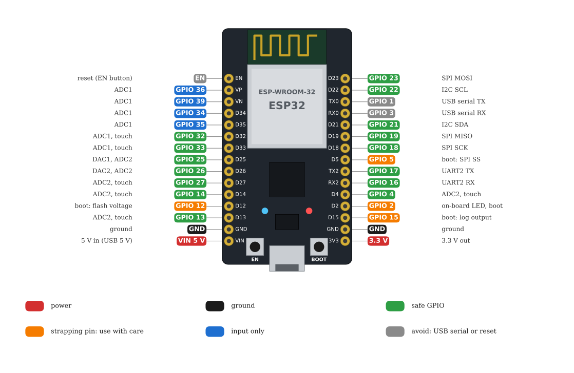
Open Espressif’s ESP32 Series Datasheet1 once and find the pin list in its section Pins. The board is only a carrier for the chip, and the datasheet of the chip is where the limits of every pin are stated. Two of them we use in this chapter: a pin must never see more than the chip’s supply plus 0.3 V, 3.6 V on our board, and a pin set as an output delivers a limited current.
Step 1: Upload the mystery signal
Create a PlatformIO project called mystery in the same way as blink, and replace its two files with the ones below. Try not to read main.cpp closely yet; for now the board is a circuit that someone else built, and we find out what it does by measuring.
[env:esp32dev]
platform = espressif32@6.13.0
board = esp32dev
framework = arduino

upload_speed = 921600
monitor_speed = 115200
monitor_echo = yes
monitor_filters = send_on_enter, esp32_exception_decoder

build_flags =
    -D BAUD=${this.monitor_speed}
    -D SIGNAL_PIN=23
    -D PERIOD_MS=2000
    -D SIGNAL_MODE=0
The program, src/main.cpp, is listed in Step 6. Build and upload as in Step 6 of the PlatformIO chapter. The serial monitor prints high and low once a second.
Step 2: Measure the signal
Unplug the USB cable, put the board on a full-size breadboard so that it straddles the centre gap, and connect a GND pin to the − rail. Plug the USB cable back in. With the meter on V⎓, black probe on the − rail and red probe on the column of D23, the reading alternates between 0 V and about 3.3 V, one second each. That is the signal: a pin that says high or low with its voltage, like Ben’s mystery wires.
Step 3: Connect an LED to the signal
The signal switches between 0 V and 3.3 V, so an LED with a resistor should blink. With the resistor formula and 220 Ω we predict
\[ I = \frac{3.3 - 1.9}{220}~\text{A} = 6.4~\text{mA}, \]
clearly visible and well within what a pin may deliver. Unplug the USB cable, and connect a 220 Ω resistor from D23 to a free column, the LED’s long leg to that column and its short leg to the − rail. This is circuit A in Figure 10.8.2. Plug in.
The LED blinks, but it is dim, much dimmer than the LEDs of the previous chapters. Ben sees the same at 3:00 in the video.
Step 4: Build a known-good reference
Is the LED dim because 3.3 V is too little for it? Build circuit B next to circuit A, with an identical resistor and an identical LED, but fed from the 3V3 pin of the board, which is a power supply. Ben does the same with his USB supply.
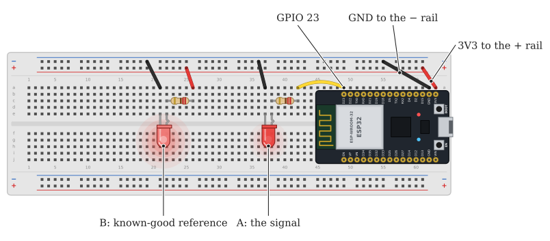
D23, circuit B by the 3.3 V supply pin 3V3. Both share the − rail, which is connected to GND. A lights only dimly, B brightly.
LED B is bright. The two circuits are meant to be identical, both “have 3.3 V”, and one works while the other does not. We have a known-good copy right next to the faulty one, which is the best position for troubleshooting there is.
Step 5: Troubleshoot
Ben’s fifth video finds the cause. Watch it, then do the same measurements on your own board, one at a time, and log each result.
Is the LED faulty? Unplug the USB, swap the two LEDs, plug in. If the dim LED moved to circuit B, the LED is faulty. It does not: A is still dim with the other LED. The LEDs are fine.
Are the resistors different? Take both out and measure them with the ohmmeter. Both read about 220 Ω. Put them back.
Is the voltage different? Take both LEDs out and measure the voltage at the free end of each resistor, black probe on the − rail. Both read 3.3 V (A only in its high second). Without a load, the two sources look the same.
Is the voltage different under load? Put the LEDs back and measure again, this time at D23 itself and at 3V3. The supply pin still reads 3.3 V. The signal pin, in its high second, reads only about 1.7 V. Connecting the LED pulled the signal down. Ben sees 5.1 V fall to 1.8 V at 6:50 in his fourth video.
Is the current different? This is the measurement Ben makes next. Unplug the USB, move the meter’s red lead to the mA jack and set the dial to mA⎓. Take LED A out and put the probes into the two holes where its legs were, red on the resistor side, so that the current has to pass through the meter (Figure 10.8.3). Plug in.
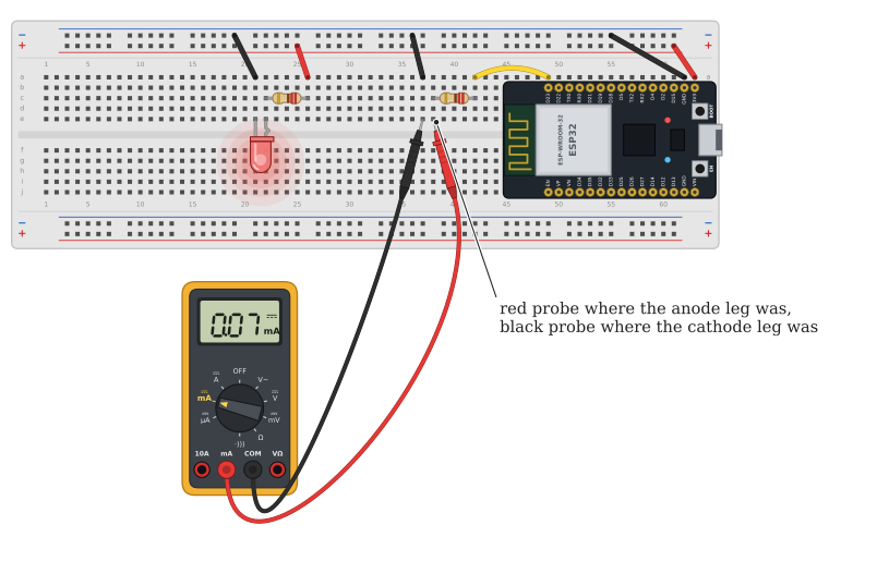
mA jack, and the current from the signal has to flow through the meter to reach ground.
In the high second the meter shows about 0.07 mA. Do the same in circuit B: about 15 mA, two hundred times more. Same voltage, same resistor, same LED, and two hundred times less current. That explains the dim LED. Unplug, put the LEDs back and, as always, move the red lead back to VΩ.
What is inside the signal
A power supply is built to hold its voltage while it delivers current; the supply pin 3V3 comes from a regulator that can deliver several hundred milliamperes. A signal is built to tell us something with its voltage, and may be able to deliver very little. The simplest picture of a weak source is an ideal voltage with a resistor inside, in series with the output. Figure 10.8.4 is that picture for our mystery pin, with 45 kΩ inside.
With nothing connected, no current flows through the hidden resistor, it takes no voltage, and the pin shows the full 3.3 V. The voltmeter draws almost nothing (with its 10 MΩ, about 0.3 µA), so it sees the 3.3 V too. That is why the measurement without a load looked fine. With the LED connected, the voltage budget of the loop now has three parts: the hidden 45 kΩ, our 220 Ω and the LED. The LED needs about 1.7 V before it conducts at all, the 220 Ω takes next to nothing, and the hidden resistor takes the rest, so the current is
\[ I = \frac{3.3 - 1.7}{45\,000 + 220}~\text{A} \approx 35~\mu\text{A}, \]
enough for a faint glow and nothing more. The pin voltage, measured behind the hidden resistor, falls to the LED voltage, the 1.7 V we measured.
A voltage measured with nothing connected says nothing about how much current the source can deliver. Measure the voltage of a source again with its load connected. If it drops noticeably, the source is weaker than the circuit needs.
Step 6: Read the code
Now open main.cpp.
#include <Arduino.h>

// SIGNAL_PIN, PERIOD_MS, SIGNAL_MODE and BAUD come from build_flags in platformio.ini
#if !defined(SIGNAL_PIN) || !defined(PERIOD_MS) || !defined(SIGNAL_MODE) || !defined(BAUD)
#error "Set SIGNAL_PIN, PERIOD_MS, SIGNAL_MODE and BAUD under build_flags in platformio.ini"
#endif

// The high half of the signal. SIGNAL_MODE 1 drives the pin as an output, connected to
// 3.3 V through the pin's output transistor. SIGNAL_MODE 0 only switches on the pin's
// internal pull-up resistor of about 45 kOhm: a voltmeter still reads 3.3 V, but the pin
// can push only a few tens of microamperes into a load.
void signalHigh() {
#if SIGNAL_MODE == 1
  pinMode(SIGNAL_PIN, OUTPUT);
  digitalWrite(SIGNAL_PIN, HIGH);
#else
  pinMode(SIGNAL_PIN, INPUT_PULLUP);
#endif
}

// The low half is the same in both modes: the output transistor connects the pin to GND.
void signalLow() {
  pinMode(SIGNAL_PIN, OUTPUT);
  digitalWrite(SIGNAL_PIN, LOW);
}

void setup() {
  Serial.begin(BAUD);
  Serial.printf("Signal on GPIO %d, period %d ms\n", SIGNAL_PIN, PERIOD_MS);
}

void loop() {
  signalHigh();
  Serial.println("high");
  delay(PERIOD_MS / 2);

  signalLow();
  Serial.println("low");
  delay(PERIOD_MS / 2);
}
In its high half the program does not make the pin an output at all. INPUT_PULLUP turns the pin into an input and connects it to 3.3 V through a resistor inside the chip, the pull-up resistor. Its job is to hold an unconnected input at a defined level, e.g. for a push button, and the ESP32 datasheet gives its typical value as 45 kΩ.2 It was never meant to feed an LED.
Change one thing: set -D SIGNAL_MODE=1 in platformio.ini and upload again. Now the program makes the pin an output, and an output pin connects to 3.3 V through a transistor with a resistance of some tens of ohms. Predict, then measure: LED A is as bright as LED B, the pin voltage under load stays near 3.2 V, and the current through the LED is about 6 mA, close to the 6.4 mA of Step 3. In Figure 10.8.4, closing the switch does the same.
How much current can a pin deliver?
An output pin is a much stronger source than the pull-up, but not a power supply either. The ESP32 datasheet3 (Table 5-3, DC Characteristics) states that a pin at its strongest drive setting sources typically 40 mA while its voltage stays above 2.64 V, and the Arduino framework uses a weaker default setting that Espressif gives as about 20 mA. These are typical values, measured with one pin loaded; with many pins loaded at once each delivers less. As with the LED in the datasheet section of the first chapter, we design well inside them.
For this course we keep the current from any one pin at or below about 10 mA. That is plenty for an LED, and the pin voltage then stays close to 3.3 V. Anything that needs more, a relay, a motor, a servo, a strip of LEDs, gets its current from a supply, and the pin only sends the signal that controls it. The part that lets a weak signal switch a strong current is the transistor, which is where Ben’s series goes next. On the car the same job is done by the motor driver of Driving a DC motor with the BTS7960: its inputs take a few milliamperes from the ESP32 pins, and it switches tens of amperes from the battery.
Which pins to use
Not every pin of Figure 10.8.1 is equally free. The table sorts them for our DevKit, following the ESP32 datasheet sections Pins and Boot configurations.
| GPIO | Use | Why |
|---|---|---|
| 4, 13, 14, 16 to 19, 21 to 23, 25 to 27, 32, 33 | Free | Ordinary input and output pins. |
| 0, 2, 5, 12, 15 | With care | Strapping pins: their level at reset decides how the chip starts. GPIO 2 also drives the onboard LED. |
| 34, 35, 36, 39 | Inputs only | No output driver and no internal pull-up or pull-down. |
| 1, 3 | Avoid | The USB serial connection used for uploads and the serial monitor. |
The pin map of the car uses only free pins and input-only pins. A strapping pin works as an ordinary pin once the board has started; the risk is a circuit that holds it at the wrong level during reset. A pull-up resistor on GPIO 12, for example, stops the board from starting at all. Why the BOOT button explains GPIO 0.
Exercises
Exercise 1: How strong is the pin?
With SIGNAL_MODE=1 and LED A in place, measure the pin voltage in the high second and the LED current. Then replace the 220 Ω by 100 Ω (never less) and measure again. Treat the pin as an ideal 3.3 V source with a hidden resistor and calculate that resistor from your two measurements.
Exercise 2: Weak sources on the car
Which of these are signals and which are supplies: the servo’s signal wire, the 3V3 pin, the midpoint of the battery divider of Voltage dividers and analog input, the VIN pin fed from the buck converter? For each signal, what is the largest current you would draw from it?
Exercise 3: The model in Falstad
In Figure 10.8.4, double-click the 45 kΩ resistor and try 4.5 kΩ and 450 Ω. For each value, note the pin voltage and the LED current. At what hidden resistance does the LED reach half of the current it gets from the supply pin?
Espressif Systems, ESP32 Series Datasheet, version 5.3: pin list in section 2, Pins; Table 5-3, DC Characteristics (3.3 V, 25 °C), for \(V_{IH}\) (at most VDD + 0.3 V), the source current \(I_{OH}\) and the pull-up \(R_{PU}\) (45 kΩ typical); Table 6-1, note 8, for the drive strength settings (default about 20 mA). espressif.com.↩︎
Espressif Systems, ESP32 Series Datasheet, version 5.3: pin list in section 2, Pins; Table 5-3, DC Characteristics (3.3 V, 25 °C), for \(V_{IH}\) (at most VDD + 0.3 V), the source current \(I_{OH}\) and the pull-up \(R_{PU}\) (45 kΩ typical); Table 6-1, note 8, for the drive strength settings (default about 20 mA). espressif.com.↩︎
Espressif Systems, ESP32 Series Datasheet, version 5.3: pin list in section 2, Pins; Table 5-3, DC Characteristics (3.3 V, 25 °C), for \(V_{IH}\) (at most VDD + 0.3 V), the source current \(I_{OH}\) and the pull-up \(R_{PU}\) (45 kΩ typical); Table 6-1, note 8, for the drive strength settings (default about 20 mA). espressif.com.↩︎