10.11 Buck converters
The battery gives between 9.6 and 12.6 V, and the servo and the ESP32 want 7.0 V. A buck converter makes the lower voltage from the higher one, and it does so with little loss of energy: it switches the battery on and off tens of thousands of times per second and smooths the pulses with an inductor and a capacitor. The car uses an XL4015 module for this. It feeds the servo, its bulk capacitor and the VIN pin of the ESP32 from one 7.0 V output, as shown in the power chain.
The guide comes first: how to set the module to 7.0 V and connect it without destroying what it feeds. How the converter works, and why it beats a simple regulator, comes after.
Buck modules are delivered with the voltage potentiometer in an arbitrary position, and they are often set high, 10 to 20 V or the full input voltage. Connected to the ESP32 or the servo before it is adjusted, the module can put the 12.6 V of the battery on them and destroy both. Set and measure the output with nothing connected to it, every time a module is new, has been borrowed, or has been out of your sight.
The Guide
The module
The modules in our kits are the CC/CV variant of the XL4015 board: two blue multi-turn potentiometers, a large toroidal inductor, two electrolytic capacitors and a row of small LEDs. One potentiometer sets the output voltage (constant voltage, CV). The other sets a current limit (constant current, CC), used e.g. to charge batteries; we turn it to its maximum so that it never limits us. The screw terminals are marked IN+, IN−, OUT+ and OUT−. Label input and output with a marker the first time you use a module, since the silkscreen is easy to misread upside down, and input and output swapped destroy the module.
The XL4015 chip itself has these ratings from its datasheet:1
| Parameter | Value |
|---|---|
| Input voltage | 8 to 36 V (absolute maximum 40 V) |
| Output voltage | 1.25 to 32 V, adjustable |
| Output current | up to 5 A (module needs cooling above about 2 to 3 A) |
| Switching frequency | 180 kHz (144 to 216 kHz) |
| Maximum duty cycle | 100 % |
| Minimum dropout | 0.3 V |
| Efficiency, 12 V to 5 V | about 90 % at 1 to 2 A, 87 % at 5 A |
Step 1: Turn the current limit to maximum
With nothing connected to the module, turn the current potentiometer clockwise until it clicks. Multi-turn potentiometers click at every turn once they reach their end stop, so a few extra turns after the first click are harmless and make sure the limit is at its maximum.
Step 2: Set the output voltage with no load
- Nothing on
OUT+andOUT−except the multimeter probes. - Connect
IN+andIN−to the car’s rail and ground (or to a bench supply at 12 V with the current limit at about 0.5 A), with the main switch off. - Set the multimeter to DC volts, red probe on
OUT+, black onOUT−. Switch on and read the starting voltage. - Turn the voltage potentiometer while watching the meter. On our modules counter-clockwise lowers the voltage. The potentiometer has 10 to 15 turns over its range, so several turns may pass before the reading changes noticeably.
- Stop at 7.0 V ± 0.1 V. If you overshoot, turn back a little.
- Tap the potentiometer gently with the screwdriver: the reading must not jump.
- Switch off. Write 7.0 V on a piece of tape on the module.
Step 3: Connect the loads and measure again
- With the switch off, connect the 470 µF bulk capacitor across
OUT+andOUT−close to the servo connector: the stripe on the capacitor marks the negative lead. Use a capacitor rated 16 V or more. - Connect the servo’s red wire to
OUT+and its brown wire toOUT−. - Connect
OUT+toVINof the ESP32 andOUT−to itsGND. Read the next section before the ESP32 is ever connected to USB at the same time. - Switch on and measure the voltage at the servo connector and at
VIN. Both should be within 0.1 V of the no-load setting. A larger drop means a poor connection or a wire that is too thin.
The bulk capacitor supplies the short current peaks the servo draws when it starts to move, which the wires and the converter cannot follow instantly. Without it, those peaks pull the 7.0 V rail down far enough to reset the ESP32.
USB and VIN at the same time
The ESP32 board has two power inputs: the 5 V of the USB connector and the VIN pin. On most DevKit boards the USB 5 V reaches the VIN node through a diode, often a Schottky diode. The diode points from USB to VIN, so it conducts when USB is higher and blocks when VIN is higher. With 7.0 V on VIN, the diode blocks and the laptop is safe.
On boards without the diode, VIN and the USB 5 V are the same copper. With the car switched on and the USB cable plugged in, the buck converter’s 7.0 V then drives current into the laptop’s USB port, which can damage the port or the laptop. A second problem exists with or without the diode: with the car switched off and USB plugged in, the laptop feeds VIN at about 4.7 V, and with it the servo and the output of the buck converter. The servo then moves weakly on USB power, and the car is not off even though the switch is.
Find out which kind of board you have before connecting both. Plug in only USB, nothing on VIN, and measure from VIN to GND:
VIN reading |
Meaning | USB and car power together? |
|---|---|---|
| 4.3 to 4.8 V | Diode present (0.2 to 0.7 V drop) | Yes, with care: switch the car on before plugging USB in, and unplug USB before switching off |
| about 5.0 V | No diode, VIN tied to USB 5 V |
Never. Program with the car off, or fit a Schottky diode |
| about 0 V | No path from USB to VIN |
Yes |
| odd low value, e.g. 0.6 V | Damaged or partly conducting diode | Treat as never until repaired |
A board without the diode can be repaired by cutting the trace from the USB 5 V to VIN and soldering a Schottky diode across the gap, anode on the USB side.
Pre-flight checklist
Before the first power-up of a newly wired circuit:
How It Works
The linear regulator, and why we do not use one
The simplest way to get 7.0 V from 12.6 V is a linear regulator: a transistor in series with the load, controlled so that it drops exactly the voltage difference. The current through the transistor is the load current, so the transistor turns the product of the two into heat:
\[ P_\text{loss} = (V_\text{in} - V_\text{out}) I. \]
With the servo and the ESP32 drawing 2 A together, from a full pack,
\[ P_\text{loss} = (12.6 - 7.0) \cdot 2~\text{W} = 11.2~\text{W}, \]
while the load receives \(7.0 \cdot 2~\text{W} = 14~\text{W}\). The efficiency is \(V_\text{out}/V_\text{in} = 7.0/12.6 = 56~\%\), and the regulator needs a heat sink the size of a matchbox to get rid of 11 W. Near the end of the pack, at 9.6 V, the loss is still \(2.6 \cdot 2~\text{W} = 5.2~\text{W}\). Almost half the battery’s energy would go into heating the regulator.
The buck topology
A buck converter avoids that loss by using a switch that is either fully on or fully off. A fully on switch has almost no voltage across it, and a fully off switch carries no current, so in neither state does it dissipate much. Figure 10.11.1 shows the ideal circuit. The switch S connects the input to the node SW for a fraction \(D\) of each switching period \(T\), the duty cycle. The inductor \(L\) between SW and the output resists changes in its current, and the capacitor \(C\) smooths the output voltage. The diode D gives the inductor current a path when the switch is off.
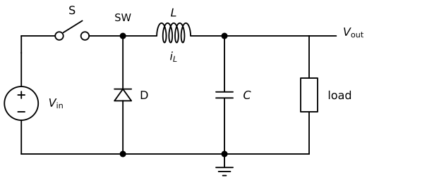
While the switch is closed, SW is at \(V_\text{in}\) and the inductor sees \(V_\text{in} - V_\text{out}\) across it. Its current grows, and the inductor stores energy in its magnetic field. When the switch opens, the inductor current cannot stop instantly: it keeps flowing, now through the diode, which puts SW at about 0 V. The inductor sees \(-V_\text{out}\) and its current falls, while the stored energy goes to the load. The current in the inductor is therefore a triangle around the load current, and the capacitor turns the remaining small ripple into a nearly constant output voltage.
The duty cycle
The voltage across an inductor is \(v_L = L \, \mathrm{d}i_L/\mathrm{d}t\). In steady state the inductor current is the same at the start of every period, so the voltage across it must average to zero over one period: the rise during the on-time equals the fall during the off-time. For the ideal converter this gives
\[ (V_\text{in} - V_\text{out}) D T = V_\text{out} (1 - D) T, \]
and solving for \(D\),
\[ D = \frac{V_\text{out}}{V_\text{in}}. \]
The output voltage is the average of the switched voltage at SW. For the car, with \(V_\text{out} = 7.0~\text{V}\):
| Pack | \(V_\text{in}\) | \(D = 7.0/V_\text{in}\) |
|---|---|---|
| Full | 12.6 V | 0.556 |
| Nominal | 11.1 V | 0.631 |
| Cutoff | 9.6 V | 0.729 |
The XL4015 measures its output through a voltage divider (the voltage potentiometer is part of it) and adjusts \(D\) continuously so that the divider’s midpoint stays at 1.25 V. As the pack discharges, the duty cycle rises from 56 % to 73 %, and the output stays at 7.0 V.
Efficiency compared
A real converter loses some power in the switch’s on-resistance, in the diode, in the inductor’s winding and in switching itself. The XL4015’s datasheet curve for 12 V to 5 V shows about 90 % efficiency between 1 and 2 A. At 90 %, the 14 W the servo and the ESP32 take at 2 A require
\[ P_\text{in} = \frac{P_\text{out}}{\eta} = \frac{14}{0.90}~\text{W} = 15.6~\text{W}, \]
so the converter loses 1.6 W, against 11.2 W for the linear regulator. The input current from a full pack is \(15.6 / 12.6~\text{A} = 1.24~\text{A}\), less than the 2 A delivered at the output. A buck converter trades voltage for current, the same way a gearbox trades speed for torque, and only a tenth of the power goes missing on the way. A linear regulator always takes the full output current from its input.
Ripple
The inductor current rises and falls by the same amount \(\Delta i_L\) in each period. During the off-time the inductor sees \(-V_\text{out}\) for \((1-D)/f\) seconds, so
\[ \Delta i_L = \frac{V_\text{out} (1 - D)}{L f}. \]
The XL4015 datasheet’s application circuit uses \(L = 47~\mu\text{H}\) (the module’s toroid is of similar size). At \(f = 180~\text{kHz}\) and a full pack (\(D = 0.556\)),
\[ \Delta i_L = \frac{7.0 \cdot 0.444}{47 \cdot 10^{-6} \cdot 180 \cdot 10^{3}}~\text{A} = 0.37~\text{A} \]
peak to peak. The ripple is largest when the input is highest, because \(D\) is smallest there. The output capacitor absorbs this triangle. For an ideal capacitor the resulting voltage ripple would be \(\Delta V = \Delta i_L / (8 f C)\), less than a millivolt with 470 µF, but real electrolytic capacitors have a series resistance (ESR) of the order of 0.1 Ω, and \(\Delta i_L \cdot \text{ESR}\) gives a ripple of some tens of millivolts at 180 kHz. The oscilloscope shows it as a small sawtooth on the 7.0 V, with sharp spikes at every switching edge. Neither the servo nor the ESP32’s own regulator notices it.
When the input sags: dropout
A buck converter can only lower a voltage. The XL4015 can raise its duty cycle up to 100 %, switch permanently on, and then the output follows the input minus the voltage drop across the switch and the inductor. The datasheet gives this minimum dropout as 0.3 V. The converter therefore holds 7.0 V as long as its input stays above about 7.3 V, and below that the 7.0 V rail follows the input down. Below 8 V the chip is also outside its specified input range.
The rail sags when the motor starts, as shown in Internal resistance and voltage sag. With a resistance of 0.06 Ω in the battery path, a 30 A start drops a full pack from 12.6 to 10.8 V and the converter does not notice. Near the cutoff, the same start takes 9.6 V down to 7.8 V, close to the dropout. An aged pack with twice the internal resistance takes it to 6.0 V, and the servo and the ESP32 sag with it.
The bulk capacitor does not help against this. It supplies the servo’s current while the voltage falls at the rate
\[ \frac{\mathrm{d}V}{\mathrm{d}t} = \frac{I}{C} = \frac{2}{470 \cdot 10^{-6}}~\text{V/s} = 4.3~\text{V/ms}, \]
so it holds the rail through microsecond peaks, not through a motor start lasting tens of milliseconds. A sagging rail is fixed at its cause: shorter and thicker battery wiring, a fresh pack, and firmware that ramps the motor up over some tens of milliseconds instead of switching it on at full duty.
The ESP32’s own 3.3 V regulator
The ESP32 runs on 3.3 V. The DevKit board makes it from VIN with a linear regulator, on most boards an AMS1117-3.3, the part used on Espressif’s own DevKitC.2 The AMS1117 needs its input at least 1.1 to 1.3 V above its output (its dropout), so VIN must be above about 4.6 V, and its absolute maximum input is 15 V.3 As a linear regulator it turns \((V_\text{in} - 3.3~\text{V}) I\) into heat.
The ESP32 draws about 240 mA while transmitting on Wi-Fi4 and less on average. With 0.2 A from the 7.0 V rail, the regulator dissipates
\[ P = (7.0 - 3.3) \cdot 0.2~\text{W} = 0.74~\text{W}. \]
The AMS1117 datasheet gives a thermal resistance from junction to air of 55 to 80 °C/W when the tab is soldered to a generous copper area, and a small DevKit board has less copper than that. With 80 °C/W the junction runs \(0.74 \cdot 80 = 59~\text{K}\) above the air, about 85 °C in a 25 °C room: warm, and within the 125 °C limit. Fed directly from a full pack instead, the regulator dissipates
\[ P = (12.6 - 3.3) \cdot 0.2~\text{W} = 1.9~\text{W}, \]
and the junction would rise about 150 K above the air. The regulator’s thermal protection switches it off before that, the ESP32 resets, the regulator cools, and the cycle repeats. 12.6 V is also uncomfortably close to the 15 V absolute maximum, and some clones are rated lower. That is why VIN is fed from the 7.0 V of the buck converter and not from the rail. Any VIN voltage from about 5 to 7 V works; we use 7.0 V because the servo wants that voltage and one converter feeds both.
Exercises
1. Duty cycle and input current. The servo and the ESP32 draw 1.5 A at 7.0 V. Compute the duty cycle and the input current of an ideal buck converter at 12.6 V and at 9.6 V. Repeat the input current for a converter with 88 % efficiency, and for a linear regulator.
2. Simulate a buck converter. In Falstad, build the circuit of Figure 10.11.1: a 12.6 V source, an analog switch controlled by a 50 kHz square wave, a diode, \(L = 100~\mu\text{H}\), \(C = 100~\mu\text{F}\) and a 5 Ω load. Set the duty cycle of the square wave to 0.556 and read the output voltage once it has settled. Then plot the inductor current and compare its ripple with the formula above. Change the source to 9.6 V: which duty cycle gives 7.0 V again?
3. Measure the efficiency. Feed the XL4015 from the bench supply at 12.0 V, set it to 7.0 V, and load it with the servo holding a position against a force. Read the input current on the bench supply and measure the output current with the multimeter in series. Compute \(\eta = V_\text{out} I_\text{out} / (V_\text{in} I_\text{in})\), and repeat at 9.6 V.
4. Find the dropout. With the module set to 7.0 V and a 10 Ω load, lower the bench supply from 12 V in steps of 0.5 V and record the output voltage. At which input voltage does the output start to follow the input, and how does that compare with the datasheet’s 0.3 V?
XLSEMI, XL4015 5A 180KHz 36V Buck DC to DC Converter, datasheet, available from the LCSC product page.↩︎
Espressif, ESP32-DevKitC V4 schematic: an AMS1117-3.3 regulator fed from the 5 V node, and a BAT760 Schottky diode in the USB supply. The 30-pin clone boards in our kits follow the same design; check the marking on the regulator of your own board (a three-pin chip with a large tab, near the USB connector).↩︎
Advanced Monolithic Systems, AMS1117 1A low dropout voltage regulator, datasheet: input voltage 15 V absolute maximum, dropout 1.1 V typical and 1.3 V maximum, junction to tab 15 °C/W, junction to ambient 55 to 80 °C/W depending on copper area, thermal shutdown at about 165 °C.↩︎
Espressif, ESP32 Series Datasheet, RF power consumption: about 240 mA when transmitting 802.11b at 19.5 dBm.↩︎