A gear tooth fails at one of two places. Figure 9.6.1 shows both in two steel gears as the pinion drives the wheel with 100 N·m. The stress gathers in the fillet at the root of the loaded tooth, which bends like a short cantilever, and in a narrow strip under the contact on the flank. Fatigue cracks start in the root fillet and break the tooth off; under the contact a steel flank pits and a plastic flank wears. A gear is rated against both.
Figure 9.6.1: Von Mises stress in the gears of Example 1 as the pinion (below) drives the wheel (above) through three teeth, from the finite element model of Gear tooth contact in Gridap. Left: the meshing zone. Top right: the whole pair. Bottom right: the largest principal stress in the tension fillet of the two marked teeth against the position \(s\) of their contact on the line of action, with the zones of double and single contact and the Lewis stresses as dashed lines.
Tooth forces and Lewis’s equation
The force between two involute teeth acts along the line of action, at the pressure angle \(\varphi\) to the tangent of the pitch circles. With the pinion torque \(T_1\) and pitch diameter \(d_1\), its tangential part carries the torque and its radial part pushes the gears apart:
The tooth is a short cantilever loaded by this force, and it breaks at its root. In 1892, Wilfred Lewis (biography) treated it as a beam of constant strength, the parabola inscribed in the tooth that touches the root fillets, loaded by \(F_t\) at the tip of the tooth. According to [1], the bending stress at the root is then
\[
\sigma = \frac{F_t}{b\,m\,Y}
\tag{9.6.2}\]
with the face widthsv. kuggbredd\(b\) and the Lewis form factor\(Y\), a pure number that depends only on the tooth shape. For \(20°\) full-depth teeth it grows from 0.245 for 12 teeth to 0.322 for 20, 0.359 for 30 and 0.485 for a rack [1, Table 14-2].
The equation carries two assumptions that limit it. It puts the whole force on one tooth at its tip, the worst place, although a second pair of teeth shares the load whenever the tooth is near its tip. And it ignores the stress concentration in the root fillet. The rating standards correct both with factors (ISO 6336).
Contact ratio
Two teeth touch only while their point of contact lies on the line of action between the two tip circles (Figure 9.2.8). That stretch has the length
with the tip radii \(r_a = r + m\), the base radii \(r_b = r\cos\varphi\) and the centre distance \(a\) of 9.5.1. Successive teeth follow each other along the line of action at the base pitch\(p_b = \pi m\cos\varphi\), so the contact ratiosv. ingreppstal
\[
\varepsilon = \frac{L}{p_b}
\tag{9.6.4}\]
is the mean number of tooth pairs in contact. Spur gears have \(\varepsilon\) between 1.4 and 1.8, so a tooth shares its load with the next pair near the ends of the stretch and carries it alone in the middle.
Example 1: tooth stress in two steel gears
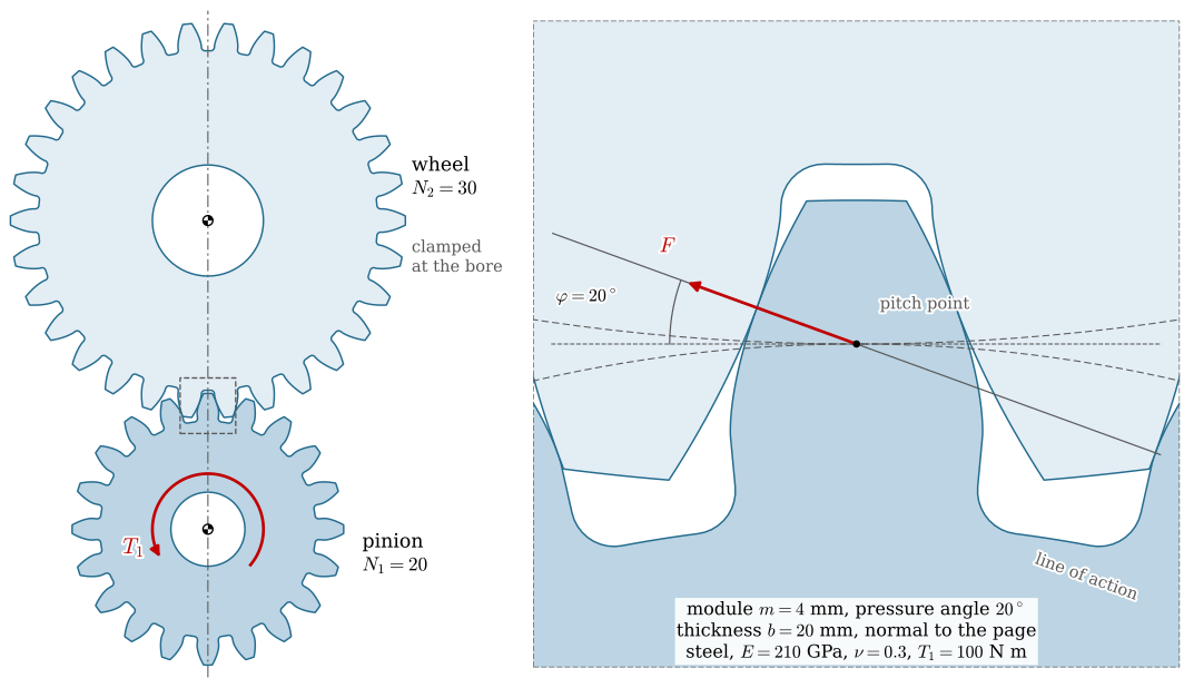
A pinion of \(N_1 = 20\) teeth drives a wheel of \(N_2 = 30\), module \(m = 4\) mm, pressure angle \(20°\), both of steel, \(E = 210\) GPa and \(\nu = 0.3\), and the gears are \(b = 20\) mm wide (Figure 9.6.2). The pinion torque is \(T_1 = 100\) N·m. Find the tooth forces, the contact ratio and the Lewis stresses, and compare the Lewis stresses with the root stresses of the finite element model of Figure 9.6.1.
Figure 9.6.2: The gears of Example 1, and the teeth at the pitch point zoomed. The tooth force \(F\) acts along the line of action at the pressure angle; the gears are \(b = 20\) mm wide, normal to the page.
The forces from 9.6.1, the contact ratio from 9.6.4 and the Lewis stresses from 9.6.2 are
\[ \begin{aligned}F_t &=2500.0~\text{N},\quad F_r =909.9~\text{N},\quad F =2660.0~\text{N}\\ L &=18.95~\text{mm},\quad p_b =11.81~\text{mm},\quad \varepsilon =1.605\\ \sigma_1 &=97.05~\text{MPa},\quad \sigma_2 =87.05~\text{MPa}\end{aligned} \]
The model behind Figure 9.6.1, described in Gear tooth contact in Gridap, treats each gear as a plane elastic body clamped at its bore. It applies these forces where the involute theory puts them and splits the force equally between two pairs in contact.
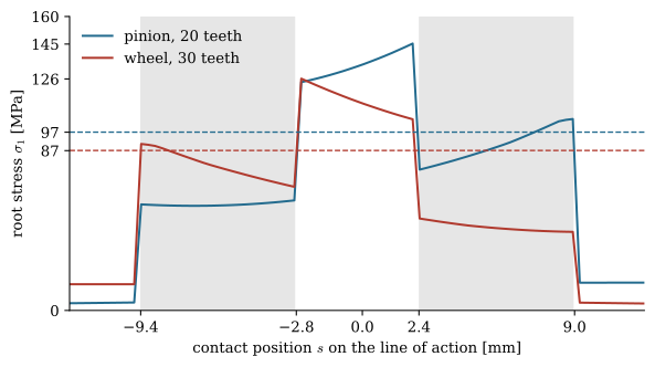
Every pair of teeth runs through the same cycle. It comes into contact at the pinion’s root and the wheel’s tip while the pair ahead still carries half the load. When that pair leaves, the whole force jumps onto the new pair and its root stresses double. In the middle of the stretch the pair carries the load alone: the wheel’s root stress falls and the pinion’s rises as the contact climbs the pinion tooth, until the next pair arrives and takes half. Figure 9.6.3 reads the root stresses of the marked teeth from the results.
Figure 9.6.3: Largest principal stress in the tension fillet of a pinion tooth and a wheel tooth over one passage through the mesh, from the finite element model, against the Lewis estimate (dashed). The grey bands are the double-contact zones.
In single contact the finite element stresses exceed Lewis’s by about half:
Two effects pull in opposite directions. Lewis puts the force at the tip, but the single pair never carries it there: the second pair takes half the load before the contact reaches the tip, so the largest moment arm in single contact is shorter than Lewis assumes. The fillet, which Lewis treats as a smooth beam, concentrates the stress, and that wins: most of the factor of about 1.5 is the stress concentration of the root fillet of radius \(0.3m\). Lewis’s equation is a sound way to size a gear’s module and face width, provided its allowable stress has room for this factor.
The model also shows a stress that Lewis leaves out. The opposite fillet of each tooth is in compression, and its von Mises stress is even higher, up to 170 MPa on the pinion, because the radial component of the force adds to the bending there. Gear teeth fail in fatigue from the fillet in tension, where cracks open.
Contact stress on the flank
Near the point of contact each involute flank is close to a circle whose radius is the involute’s radius of curvature, the distance along the line of action from the contact point to the point where the line touches that gear’s base circle. At the pitch point this is \(\rho = r\sin\varphi\). Two elastic cylinders pressed together touch over a narrow strip. According to Hertz’s theory, in the form of [1, Eqs. 3-73 and 14-10] for two bodies with the same \(E\) and \(\nu\), the half-width of the strip and the largest pressure in it are
The pressure is largest at the surface, but the largest shear stress lies below it, at 0.786 half-widths [1]. Pitting starts there: a crack grows below the surface, parallel to it, until a flake of the flank breaks out. Gear tooth contact in Gridap solves this contact with finite elements and finds both.
ISO 6336-2 [2] writes the same pressure at the pitch point with the ratio \(u = N_2/N_1\), \(\rho_2 = u\rho_1\) and \(F = F_t/\cos\varphi\) as the nominal contact stress
where the elasticity factor\(Z_E\) carries the material and the zone factor\(Z_H\) the curvature of the flanks. The code below checks that 9.6.6 is 9.6.5, and at the pitch point of Example 1, where one pair carries the whole force, it gives
Code
# Hertz at the pitch point of Example 1E_g, nu_g =210e3, 0.3# MPa, -rho_1, rho_2 = r_1*np.sin(phi), r_2*np.sin(phi)a_H = np.sqrt(8*F_g*(1- nu_g**2)/(np.pi*b_g*E_g)*rho_1*rho_2/(rho_1 + rho_2))p_H =2*F_g/(np.pi*a_H*b_g)u_g = N_b/N_aZ_E = np.sqrt(E_g/(2*np.pi*(1- nu_g**2)))Z_H = np.sqrt(2/(np.sin(phi)*np.cos(phi)))sig_H0 = Z_E*Z_H*np.sqrt(F_tg/(b_g*2*r_1)*(u_g +1)/u_g)# the same identity in symbols: Hertz pressure squared minus the ISO form squaredFt, d, u, b, ph, E, nu = sp.symbols('F_t d_1 u b varphi E nu', positive=True)r1 = d/2*sp.sin(ph)aH2 =8*Ft/sp.cos(ph)*(1- nu**2)/(sp.pi*b*E)*r1*u*r1/(r1 + u*r1)p2 = (2*Ft/sp.cos(ph)/(sp.pi*b))**2/aH2iso2 = E/(2*sp.pi*(1- nu**2))*2/(sp.sin(ph)*sp.cos(ph))*Ft/(b*d)*(u +1)/ucheck = sp.simplify(p2 - iso2)
The contact is a strip about a fifth of a millimetre wide across the face of the tooth, under a pressure five times the root stress. A hardened steel flank is rated against it for pitting, and on a gear of normalised steel the flank, not the root, sets the torque, as the load diagram shows.
Load variation in spur and helical gears
The root stress of Figure 9.6.3 follows the force on one tooth, and that force jumps whenever a pair of teeth comes into or out of contact. The graph of this force over a tooth’s passage through the mesh is the load variationsv. kraftvariation of the gear pair. Helical gears (Figure 9.6.4) smooth it out.
Figure 9.6.4: The gears of Example 1 as helical gears, helix angle \(20°\), the pinion right-hand and the wheel left-hand. Each tooth comes into mesh at one face and the contact travels across the face width as the gears turn.
All contacts of a gear pair lie in the plane of action, the plane through the line of action parallel to the axes. The part of it where the teeth can touch is a rectangle, the length of action \(L\) of 9.6.3 long and the face width \(b\) wide. A spur tooth touches its mate along a line across the whole face, parallel to the axes, and the lines of successive teeth follow each other along the rectangle one base pitch \(p_b\) apart. A helical tooth touches along a line inclined at the base helix angle\(\beta_b\), \(\tan\beta_b = \tan\beta\cos\varphi\), so its line enters the rectangle at one corner, grows as the gears turn, and leaves the opposite corner as gradually as it came.
Figure 9.6.5 cuts the helical pinion at a depth that moves through its thickness: every cut is a spur pair, and its contact points trace the inclined contact lines.
Figure 9.6.5: The pinion of Figure 9.6.4 cut at a depth \(z\) that moves through its thickness, the gears standing still. The section (hatched) and the wheel’s section in the same plane (black outline) are a spur gear pair; the red dots are their contact points. Below the cut, the red lines are the contact lines across the pinion’s flanks. Right: the plane of action seen face on, where the contact lines are straight and inclined, and the cut meets them at the contact points of the section.
A contact line spans \(b\tan\beta_b\) along the line of action, and that, in base pitches, adds the overlap ratio to the contact ratio,
the total contact ratio, the mean number of teeth in contact.
To turn the contact lines into forces we assume that the teeth are equally stiff along the lines, so that the force per unit length of contact line is the same on all of them. A tooth whose line has the length \(\ell_k\) inside the rectangle then carries the share
of the force, where \(s_k\) is the position of the line at mid-face, the bracket is one where the line is inside the rectangle and zero elsewhere, and the line of the next tooth lies at \(s_k + p_b\). For a spur gear, \(\beta_b = 0\), each line is in or out as a whole, and 9.6.8 reduces to the equal split of Example 1.
Code
s_a0 =-np.sqrt((r_2 + m_g)**2- (r_2*np.cos(phi))**2) + r_2*np.sin(phi) # wheel's tips_r0 = np.sqrt((r_1 + m_g)**2- (r_1*np.cos(phi))**2) - r_1*np.sin(phi) # pinion's tipz = np.linspace(-b_g/2, b_g/2, 2001)def load_share(beta_deg, s):# share of the force on the tooth whose contact line is at s (mid-face), eq-tr-load-share tb = np.tan(np.radians(beta_deg))*np.cos(phi)def length(sk): # the part of the line inside the rectangle inside = (s_a0 <= sk[:, None] + z*tb) & (sk[:, None] + z*tb <= s_r0)return inside.mean(axis=1)*b_g*np.sqrt(1+ tb**2) total =sum(length(s + k*p_b) for k inrange(-4, 5))return length(s)/total, b_g*tb/p_bs_line = np.linspace(s_a0 -12, s_r0 +12, 1500)share_spur, _ = load_share(0, s_line)share_hel, eps_beta = load_share(20, s_line)
Code
fig, ax = plt.subplots(figsize=(7, 3.2))ax.plot(s_line, share_spur, color=BLUE, label=r'spur, $\beta = 0$')ax.plot(s_line, share_hel, color=RED, label=r'helical, $\beta = 20^\circ$')ax.set_xlim(s_line[0], s_line[-1])ax.set_ylim(0, 1.05)ax.set_xticks([round(s_line[0], 1), round(s_a0, 1), 0, round(s_r0, 1), round(s_line[-1], 1)])ax.set_yticks([0, 0.5, round(share_hel.max(), 2), 1])ax.set_xlabel('position $s$ of the tooth\'s contact line at mid-face [mm]')ax.set_ylabel('$F_k/F$')ax.legend(loc='upper left', frameon=False)for side in ('top', 'right'): ax.spines[side].set_visible(False)plt.show()
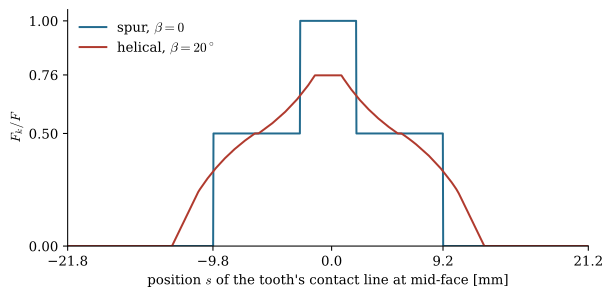
Figure 9.6.6: The load variationsv. kraftvariation of one tooth of the gears of Example 1 as spur gears and as helical gears with \(\beta = 20°\) and the same transverse geometry, from 9.6.8: the share of the tooth force \(F\) that the tooth carries as its contact line passes through the plane of action.
The spur tooth of Figure 9.6.6 takes half the force at once, all of it a moment later, then half again, and lets go of it at once. Every step is a jump in the deflection of the teeth, which the gears make heard as a knock and the drive feels as a vibration at the tooth frequency. The helical tooth takes up its load and puts it down gradually, the total length of contact line hardly changes as the gears turn, and the largest share of a tooth stays well below the whole force. Helical gears therefore run more quietly and carry more load for the same size.
The assumption of equal stiffness per unit length is the weak point of 9.6.8: a line near the tip of a tooth meets a softer tooth than one near the root, and the rating standards correct for this with load distribution factors. Sharing the force by the stiffness of the teeth turns the spur staircase into a ramp: an entering pair takes 40 % of the force, and the root stress in double contact drops by up to 19 %, while the largest root stress, in single contact, does not change (Gear tooth contact in Gridap).
The load diagram
A gear supplier’s catalogue answers the designer’s first question, how much torque a gear of a given module and number of teeth can carry, with a load diagramsv. belastningsdiagram: the torque against the number of teeth on logarithmic axes, one line per module. We build one from the root and flank limits and check it against the load diagrams of a Swedish supplier’s catalogue [3].
The flank limit follows from 9.6.5. At the pitch point the radii of curvature are \(\rho_1 = (d_1/2)\sin\varphi\) and \(\rho_2 = u\rho_1\), and the tooth force is \(F = 2T/(d_1\cos\varphi)\). Inserting these and requiring the largest pressure to stay below the allowable flank pressure \(\sigma_{HP}\) gives the torque the flank carries:
Code
T, d_1, u, b, phi_s, E_s, nu_s, sig_HP = sp.symbols(r'T d_1 u b varphi E nu sigma_HP', positive=True)rho_1 = d_1/2*sp.sin(phi_s)rho_2 = u*rho_1F_n =2*T/(d_1*sp.cos(phi_s))a_h = sp.sqrt(8*F_n*(1- nu_s**2)/(sp.pi*b*E_s)*rho_1*rho_2/(rho_1 + rho_2)) # eq-tr-hertzp_max =2*F_n/(sp.pi*a_h*b)T_H = sp.solve(sp.Eq(p_max**2, sig_HP**2), T)[0]Z_E2, Z_H2 = E_s/(2*sp.pi*(1- nu_s**2)), 2/(sp.sin(phi_s)*sp.cos(phi_s))check = sp.simplify(T_H - sig_HP**2*b*d_1**2*u/(2*Z_E2*Z_H2*(u +1))) # zero: the ISO form
\[ T_H =\dfrac{\pi b d_{1}^{2} \sigma_{HP}^{2} u \left(1 - \nu^{2}\right) \sin{\left(2 \varphi \right)}}{4 E \left(u + 1\right)} \]
This is 9.6.6 solved for the torque with \(\sigma_{H0} = \sigma_{HP}\), \(T_H = \sigma_{HP}^2\, b\, d_1^2\, u/(2 Z_E^2 Z_H^2 (u + 1))\); the code above checks that the two forms agree. The root limit follows from Lewis’s equation 9.6.2 with the fillet’s stress concentration \(K_t\) that Example 1 measured and the allowable local root stress \(\sigma_{FP}\). With \(d_1 = mN_1\) the two limits are, as mechanicskit.gears computes them,
and the gear carries the smaller of the two. On logarithmic axes both are straight lines for each module. The flank limit rises with the square of the number of teeth, slope 2, because a larger gear has flatter flanks that spread the contact; the root limit rises only as \(N_1 Y\), a slope of about 1.3. Depending on the material, the flank or the root governs.
The allowable stresses come from the materials of Table 9.6.1. The catalogue’s steel, C45, is close to AISI 1045, 179 HB cold-drawn [1, Table A-20], and for normalised steel ISO 6336-5 [4] gives the allowable stresses as straight lines in the hardness. Its \(\sigma_{F\lim}\) is a nominal root stress that already contains a stress concentration of 2, so the local stress the material bears is \(2\sigma_{F\lim}\). The catalogue states its safety factors and face widths, and that its torques hold for the smaller gear; we take \(u = 1\), equal gears, where the flank pressure is highest. For polyacetal (POM) we found no reliable published allowable flank pressure, so we fit it to the catalogue’s plastic diagram.
HB is the Brinell hardness: a hard ball is pressed into the surface with a known force, and the force divided by the area of the dent, in kgf/mm², is the hardness. A steel’s ultimate strength is roughly \(3.4\,\text{HB}\) MPa [1], so hardness stands in for strength in the rating standards.
Table 9.6.1: Materials of the load diagram. The hardness lines are those of ISO 6336-5 for normalised steel of the usual material quality; the POM root value is the fatigue strength of VDI 2736 for \(10^7\) cycles at 20 °C.
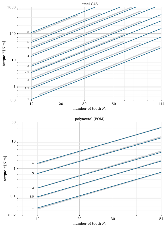
Figure 9.6.7: The load diagramsv. belastningsdiagram from 9.6.9, one line per module (the number at its left end), for steel (top) and for polyacetal gears (bottom) with the catalogue’s face widths and \(u = 1\) (blue), over the lines of the catalogue’s load diagrams [3] (grey). The flank limit governs every line.
The steel model reproduces the catalogue’s diagram from first principles: the slope of 2, which the catalogue lines have to three digits, and the torques to within the ratio above, about 15 % below the catalogue. The difference is the hardness. The catalogue’s lines match \(\sigma_{HP} \approx 400\) MPa, which ISO 6336-5 gives normalised steel of 210 HB, the top of its range and harder than the cold-drawn 1045 of Shigley’s table. The module 8 line of the catalogue lies 20 % below the others, which no factor in 9.6.9 explains, so we take it for a drawing error. The root never governs a steel gear of this kind: even with 114 teeth the root carries several times the torque the flank does.
The catalogue’s plastic lines also have slope 2, so they too are a flank limit, and fitting them gives the allowable flank pressure of POM above, about 15 MPa. Polyacetal gears that run dry wear and heat up, and the teeth soften as they warm, long before the root breaks: the root limit of 9.6.9 lies far above the catalogue’s lines. VDI 2736 therefore checks plastic gears for temperature and wear as well as for stress (plastic gears).
WarningPrinted gears have no load diagram yet
The strength of a gear printed by fused-filament fabrication depends on the polymer, on the orientation of the layers relative to the tooth, on how well the layers are fused, and on the temperature the teeth reach in running. Print settings alone changed the wear life of printed gears threefold in one study [8], and neither VDI 2736 nor the published tests cover the filaments and settings we print with. The diagram for printed gears has to come from mechanical testing: fatigue tests of printed teeth in the orientations we print, and running tests of gear pairs at known torque and speed that measure wear and tooth temperature. 9.6.9 then needs only the two allowable stresses those tests give.
The notebook below draws the load diagram for any material hardness, face width, gear ratio and safety factors, and shows which limit governs a chosen gear.
ISO 6336 keeps the two cores of this chapter, Lewis’s root stress and Hertz’s contact pressure, and adds factors for what the hand model leaves out (Table 9.6.2). Part 3 [9] rates the root,
The first fraction of 9.6.10 is Lewis’s stress with \(1/Y\) split in two. The form factor \(Y_F\) takes the bending moment with the force at the outer point of single contact, where one tooth carries it alone, so the contact ratio is already inside it; the stress correction factor \(Y_S\) is the fillet’s stress concentration that Example 1 measured as 1.5. The square root in 9.6.11 is 9.6.6, and the load factors stand under a root because the contact pressure grows with the square root of the force.
Table 9.6.2: The factors of ISO 6336 and what each one adds to Lewis and Hertz [2,9,10].
what the hand model leaves out
root
flank
shocks from the driving and the driven machine
\(K_A\)
\(K_A\)
dynamic load from tooth errors and the varying mesh stiffness
\(K_v\)
\(K_v\)
uneven load across the face width (shaft deflection, misalignment)
\(K_{F\beta}\)
\(K_{H\beta}\)
uneven split between the pairs in contact
\(K_{F\alpha}\)
\(K_{H\alpha}\)
tooth shape and the point of single contact
\(Y_F\)
\(Z_H\), \(Z_B\), \(Z_\varepsilon\)
stress concentration in the root fillet
\(Y_S\)
helix of the teeth
\(Y_\beta\)
\(Z_\beta\)
elastic constants of the pair
\(Z_E\)
strength of the test gear converted to this gear: life, notch sensitivity, roughness, lubricant, speed, size
The application factor \(K_A\) is the service factor of a geared motor’s catalogue, defined in ISO 6336-1 [10]; it multiplies the nominal torque for the shocks of the driving and the driven machine, from 1.0 when both run smoothly to 2.25 and more when both deliver heavy shocks. The strength side starts from the endurance limits \(\sigma_{F\lim}\) and \(\sigma_{H\lim}\) of ISO 6336-5, measured on standard test gears. \(Y_{ST} = 2\) turns the nominal root limit into the local stress of the test gear, the factor of 2 in Table 9.6.1, and the remaining factors correct for a finite life and for the ways this gear differs from the test gear. \(S_{F\min}\) and \(S_{H\min}\) are the minimum safety factors.
Plastic gears to VDI 2736
Plastic gears fail in ways steel gears do not. Their strength falls as they warm, they run dry and wear, and their teeth bend far enough under load to change the mesh. VDI 2736 [6] rates thermoplastic spur gears with the forms of ISO 6336 and adds checks for these (Table 9.6.3).
Table 9.6.3: The checks of VDI 2736 for thermoplastic spur gears [6].
check
what it limits
why a plastic gear needs it
temperature
the flank and root temperatures, from the power, the friction of the material pair, the geometry and how well the housing sheds heat
a plastic gear conducts heat poorly and runs well above the room, and every strength is read at its running temperature
root
the root stress, as in ISO 6336
the tooth breaks in fatigue, as a steel tooth does
flank
the contact stress, as in ISO 6336
a lubricated plastic flank pits
wear
the flank material lost over the life, from a wear coefficient of the material pair
a gear that runs dry wears
deformation
the deflection of the tooth tip
a tooth that bends too far meets its mate early, before the line of action
The strengths are measured on moulded gears of each polymer, such as the 41 MPa root fatigue strength of POM at 20 °C [7].
For a printed gear the guideline gives the method and none of the numbers. Its materials are moulded polymers, not PLA or PETG, and a printed tooth has layers that bond less well than the polymer holds together, so its strength depends on the direction of the layers through the tooth (print orientation).
Example 2: a printed motor pinion
The conveyor drive of Example 2 in the transmissions chapter is rebuilt with a first stage of 20 and 105 teeth, the same ratio of 5.25, so that the motor pinion becomes the pinion of Figure 9.2.6 at \(m = 1\) mm. It is printed in PLA, \(b = 8\) mm wide. In running the motor gives \(T_1 = 0.032\) N·m; when the belt jams it stalls and gives \(T_s = 0.15\) N·m. Find the local root stress with the fillet factor of Example 1 and the contact stress at the pitch point for both torques, and compare them with the POM values of Table 9.6.1. For the elastic constants we take those of POM, \(E = 3100\) MPa and \(\nu = 0.35\)[5].
Code
N_1p, N_2p, m_p, b_p =20, 105, 1.0, 8.0# teeth, mmE_p, nu_p =3100.0, 0.35# MPa, POM as a stand-in for PLAT_p = np.array([0.032, 0.15])*1e3# running and stalled [N mm]K_t = sig_fe1/sig_L1 # fillet factor from Example 1d_1p, u_p = m_p*N_1p, N_2p/N_1pF_tp =2*T_p/d_1psig_F = K_t*F_tp/(b_p*m_p*lewis_form_factor(N_1p)) # local root stressZ_Ep = np.sqrt(E_p/(2*np.pi*(1- nu_p**2)))sig_H = Z_Ep*Z_H*np.sqrt(F_tp/(b_p*d_1p)*(u_p +1)/u_p)b_stall = b_p*(sig_H[1]/pom['sig_HP'])**2# width that keeps the stalled flank at the POM limit
Running and stalled, the tooth force, the local root stress and the contact stress are
The root is far from any limit: even stalled, its local stress of 8.7 MPa is a fifth of the 41 MPa that VDI 2736 allows a moulded POM tooth. The flank is the limit, as the load diagram predicts for plastic gears. Running, its 9.1 MPa lies below the 15 MPa fitted to the catalogue’s POM lines; stalled, its 20 MPa lies above. A drive that stalls often needs a wider pinion, and since \(\sigma_{H0}\) falls as \(1/\sqrt{b}\), the stalled flank comes down to the POM value at
\[ b = 8~\text{mm}\left(\frac{\sigma_{H0,\text{stall}}}{\sigma_{HP,\text{POM}}}\right)^2 =13.3~\text{mm} \]
These comparisons are with an injection-moulded polymer at room temperature. PLA softens near 60 °C (creep and softening), so a printed PLA pinion on a motor shaft that runs warm is weaker by amounts nobody has measured for our printers. Only a running test of the printed pair, at the stall torque and at the running torque, settles whether 8 mm or 13 mm is enough.
TipIn industry: rating software
Nobody sizes a production gearbox with Lewis’s equation alone. Gear manufacturers rate their gears to ISO 6336 or AGMA 2001 with calculation software such as KISSsoft, which takes the full geometry, the accuracy grade, the shafts and bearings that set \(K_{H\beta}\), and the load spectrum, and returns safety factors for the root and the flank. Pitting, not tooth breakage, usually limits a hardened gear. Plastic gears are rated to VDI 2736 in the same programs, with material data from the polymer suppliers.
Problems
Problem 1: Sizing by Lewis. The gears of Figure 9.6.2 are to carry \(T_1 = 250\) N·m with the same teeth, \(N_1 = 20\) and \(N_2 = 30\). The steel allows 190 MPa in bending at the root, and the finite element results of Example 1 show that the true root stress is about 1.5 times Lewis’s. Which module is needed with \(b = 10m\)?
Answer:\(F_t = 2T_1/(mN_1)\) and \(\sigma = 1.5\,F_t/(b m Y) = 1.5 \cdot 2T_1/(10\,m^3 N_1
Y) \le 190\) MPa give \(m^3 \ge 1.5 \cdot 2 \cdot 250 \cdot 10^3/(10 \cdot 20 \cdot 0.322
\cdot 190) = 61.3\) mm³, \(m \ge 3.94\) mm: module 4 with \(b = 40\) mm.
Problem 2: The 12-tooth pinion. The conveyor drive of Example 2 in the transmissions chapter keeps its 12/63 first stage, \(m = 1\) mm and \(b = 8\) mm, with the elastic constants and the fillet factor of Example 2. Find the local root stress and the contact stress at stall, \(T_s = 0.15\) N·m, and the face width that brings the stalled flank down to 15.4 MPa.
Answer:\(F_t = 25\) N, \(Y = 0.245\), \(K_t\sigma = 1.5 \cdot 25/(8 \cdot 1 \cdot 0.245)
= 19\) MPa. With \(u = 5.25\), \(\sigma_{H0} = 23.7 \cdot 2.49\sqrt{25/(8 \cdot 12) \cdot
6.25/5.25} = 33\) MPa, and \(b = 8 \cdot (33/15.4)^2 \approx 37\) mm. A pinion that small and that wide is a poor design; a 20-tooth pinion, as in Example 2, or a larger module is the better answer.
Further reading
Budynas and Nisbett [1, Ch. 14] derive Lewis’s equation and the AGMA rating method that corresponds to ISO 6336 [2,9,10]. Tavčar and co-authors [5] describe how polymer gears are designed against the criteria of VDI 2736 [6].
ISO 6336-2:2019 Calculation of load capacity of spur and helical gears – Part 2: Calculation of surface durability (pitting). Geneva, Switzerland: International Organization for Standardization; 2019.
ISO 6336-5:2016 Calculation of load capacity of spur and helical gears – Part 5: Strength and quality of materials. Geneva, Switzerland: International Organization for Standardization; 2016.
[5]
Tavčar J, Černe B, Duhovnik J, Zorko D. A multicriteria function for polymer gear design optimization. Journal of Computational Design and Engineering 2021;8:581–99. https://doi.org/10.1093/jcde/qwaa097.
[6]
VDI 2736 Blatt 2: Thermoplastische Zahnräder – Stirnradgetriebe – Tragfähigkeitsberechnung. Berlin: Verein Deutscher Ingenieure; Beuth; 2014.
Zhang Y, Mao K, Leigh S, Shah A, Chao Z, Ma G. A parametric study of 3D printed polymer gears. The International Journal of Advanced Manufacturing Technology 2020;107:4481–92. https://doi.org/10.1007/s00170-020-05270-5.
[9]
ISO 6336-3:2019 Calculation of load capacity of spur and helical gears – Part 3: Calculation of tooth bending strength. Geneva, Switzerland: International Organization for Standardization; 2019.
[10]
ISO 6336-1:2019 Calculation of load capacity of spur and helical gears – Part 1: Basic principles, introduction and general influence factors. Geneva, Switzerland: International Organization for Standardization; 2019.