A shaft that turns has to be held in place without being held still. Its bearingssv. lager let it turn about its own axis and stop every other motion: they carry the weight of a rotor, the pull of a belt and the thrust of a helical gear into the housingsv. lagerhus, at the speed of the shaft and with little friction. A rolling bearingsv. rullningslager does this with balls or rollers between two rings, a plain bearingsv. glidlager with a sliding surface and, in most cases, a film of oil.
Bearings are bought. The boundary dimensions of a 6204, a 20 mm bore, a 47 mm outside diameter and a width of 14 mm, follow ISO 15 [1] and are the same from every maker, and the makers publish load ratings, life formulas and selection tools calibrated on their own test rigs. The designer does not decide what goes on inside the bearing. The designer decides everything around it: which type goes where, which bearing holds the shaft axially and which one lets it grow, which ring is pressed on and which one slides, and what holds the rings. These decisions follow from the kind of load and from the application, and they are the subject of this chapter. Most of it is drawings of shafts in their housings, because a bearing arrangement is read off a drawing.
We start with the bearing types and the load each one is made for, then put two bearings on a shaft and see how they share the work of locating it. Nine examples, from an electric motor to a ball screw axis, show the arrangements in use. Linear and plain bearings follow, then the bearing seat in a printed part, and the chapter closes with the life calculation and why it is left to the makers’ tools.
What a bearing does
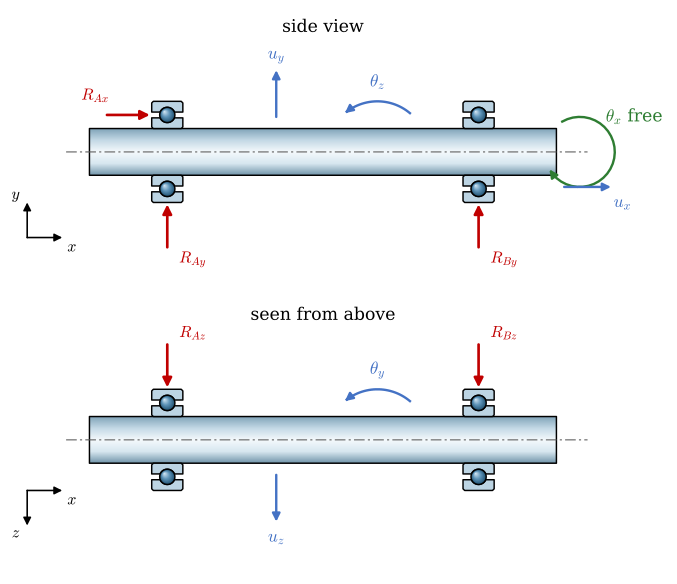
A rigid body has six degrees of freedom, and a shaft should keep one of them, the rotation about its own axis. Its bearings remove the other five (Figure 9.9.1). Each of the two bearings stops the shaft from moving sideways at its own position, two constraints per bearing, and together the four constraints remove the two translations across the axis and the two tilts. Each bearing carries these constraints as a radial load. The fifth freedom, the translation along the axis, is removed by an axial load on one bearing or on both. Which one it is turns out to be the central decision of an arrangement (9.9.1).
Figure 9.9.1: The five freedoms the bearings of a shaft remove. In each view the radial reactions at the bearings A and B stop the shift \(u\) across the axis and the tilt \(\theta\), as the two supports of a beam do; the axial reaction \(R_{Ax}\) at A stops the axial shift \(u_x\), and the turning \(\theta_x\) about the axis stays free. Seen from above, \(z\) points down the page.
A rolling bearing carries the load through balls or rollers that roll between an inner ring on the shaft and an outer ring in the housing. A cagesv. hållare keeps the rolling elements apart, and shields or sealssv. tätningar keep the grease in and the dirt out. Rolling replaces sliding, so a deep groove ball bearing runs with a friction coefficient of about 0.0015 [2] and starts almost as easily as it runs; a dry plain bearing has a hundred times that. The price is the contact itself: a ball touches its raceway on a spot a fraction of a millimetre wide, the contact pressure reaches gigapascals, and every point of the raceway is loaded and unloaded each time a ball passes. A rolling bearing fails by fatigue of its raceways, and its life is counted in revolutions (9.9.4).
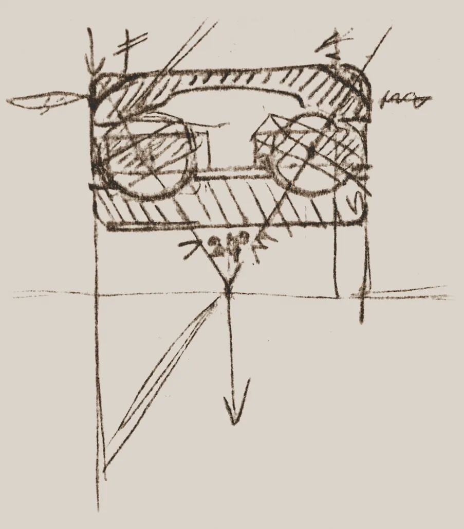
The modern ball bearing industry has Swedish roots. In 1907 Sven Wingquist, an engineer at a textile mill in Gothenburg whose line shafts kept wrecking their bearings, patented the self-aligning ball bearing and founded SKF, Svenska Kullagerfabriken, to make it. His sketch of the bearing (Figure 9.9.2) already shows what makes it self-aligning: the outer raceway is a sphere, and the load lines through both rows of balls meet at one point on the shaft axis, about which the shaft can tilt freely. The problem he solved, a shaft that does not stay in line with its bearings, returns in Example 5.
Figure 9.9.2: Sven Wingquist (1876 to 1953). Above: at his drawing board at SKF, from a company publication of about 1940 to 1945. Below: his original sketch of the self-aligning ball bearing, two rows of balls in a spherical outer raceway, the load lines meeting on the shaft axis.
Bearing types
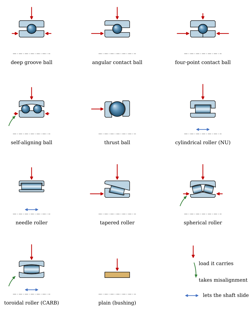
A bearing type is a choice of rolling element and raceway shape, and the choice settles which loads the bearing takes. Figure 9.9.3 shows the common types cut along the shaft axis, each with arrows for the loads it carries. Where the load line through a rolling element is inclined to the radial plane, the bearing carries axial load as well as radial; the angle between the two is the contact angle \(\alpha\).
Figure 9.9.3: The bearing types in section, upper half, the shaft axis below. Red arrows: the loads each type carries, longer for a larger share. Green arc: the bearing takes misalignment of the shaft. Blue double arrow: the shaft can slide axially inside the bearing.
The deep groove ball bearingsv. spårkullager is the default. Its balls run in grooves only slightly larger than the balls, so it takes radial load, a moderate axial load in both directions, and high speeds. It is cheap, sealed for life in most sizes, and found in electric motors, skateboard wheels, bicycles and every printer and RC car. It tolerates only a few minutes of arc of misalignment.
The angular contact ball bearingsv. vinkelkontaktkullager has one shoulder of each ring cut down, so the load line runs through the ball at a contact angle of 15° to 40°. It takes a larger axial load than the deep groove bearing, but in one direction only, and is therefore mounted in pairs, each bearing taking the thrust in its own direction (Section 9.9.3.1). Machine tool spindles run on sets of them. The four-point contact ball bearingsv. fyrpunktskontaktkullager has a split inner ring and two contact angles, and carries axial load in both directions. It is often paired with a cylindrical roller bearingsv. cylindriskt rullager that takes the radial load, the four-point bearing’s outer ring left loose in the housing so that it carries only the thrust. The self-aligning ball bearingsv. sfäriskt kullager has two rows of balls and an outer raceway ground as a sphere centred on the axis, so the inner ring and the balls can tilt with the shaft by a few degrees without loading anything; it has the lowest friction of all rolling bearings [2]. The thrust ball bearingsv. axialkullager has its raceways in two washers across the axis and carries axial load in one direction and nothing radial.
Rollers touch their raceways along a line instead of at a point, which raises the load capacity and lowers the speed limit. The cylindrical roller bearing carries large radial loads. In the NU design of Figure 9.9.3 the ribs that guide the rollers are on the outer ring only, so the inner ring slides under the rollers: the bearing carries no axial load at all and lets the shaft move axially inside it. This makes it the standard non-locating bearing (9.9.1); the NJ and NUP designs add ribs to the inner ring and carry some axial load. The needle roller bearingsv. nållager uses long thin rollers and has the smallest radial height of any rolling bearing; without an inner ring the needles run directly on a hardened shaft. The tapered roller bearingsv. koniskt rullager has conical rollers between a conical cone (the inner ring) and cup (the outer ring), carries large radial and axial loads together, and like the angular contact bearing works in one axial direction only, so it is always mounted against a second one; truck wheels and gearboxes run on them. The spherical roller bearingsv. sfäriskt rullager is the roller version of the self-aligning ball bearing: two rows of barrel rollers in a spherical outer raceway, heavy loads, shocks and 1.5° to 3.5° of misalignment [2]. The toroidal roller bearing, sold by SKF as CARB, has one row of long barrel rollers between two curved raceways and takes both misalignment and axial movement, the non-locating partner of a spherical roller bearing. Its thrust counterpart, the spherical roller thrust bearingsv. sfäriskt axialrullager, carries the thrust of ship propellers.
The plain bearing, last in Figure 9.9.3, is a bushing: a sleeve of bronze or polymer in which the shaft slides (9.9.3).
Why so many types? Because a bearing is chosen for the load it sees. A deep groove ball bearing would carry the radial load of a conveyor drum, but not the misalignment of its long shaft; a cylindrical roller bearing would carry the radial load of a gear shaft, but not the axial force from the helical teeth. The type follows from the load: its kind (radial, axial or both, one way or two), its size, the speed, the misalignment, the axial movement the bearing has to allow, shocks and temperature.
Arranging the bearings on a shaft
Two bearings remove the four transverse freedoms of a shaft, and the axial one must be removed too, but only once. The reason is temperature. A shaft carries the heat of a motor’s rotor or of the friction in the bearings, and it runs warmer than the housing around it. Its free growth over the bearing distance \(L\) is
\[
\Delta L = \alpha_T\,\Delta T\,L
\tag{9.9.1}\]
with the coefficient of thermal expansion \(\alpha_T\) and the temperature difference \(\Delta T\) between shaft and housing, the thermal strain\(\alpha_T\Delta T\) over the length \(L\). If both bearings held the shaft axially, the housing would stop that growth, and the shaft would be the bar between two rigid walls of statics: compressed by the force \(F = EA\,\alpha_T\Delta T\) that pushes it back to its original length. For a steel shaft of \(d = 30\) mm with bearings 300 mm apart, running 30 K warmer than its housing:
Code
alpha_T, E_st =12e-6, 210e3# steel: thermal expansion [1/K], Young's modulus [MPa]L_sh, d_sh, dT =300.0, 30.0, 30.0# bearing distance and shaft diameter [mm], dT [K]dL = alpha_T*dT*L_sh # free growth between the bearings, @eq-br-growth [mm]F_lock = E_st*np.pi*d_sh**2/4*alpha_T*dT # the force that would stop it [N]
The shaft wants to grow by a tenth of a millimetre, and stopping it takes
\[ \begin{aligned}\Delta L &=0.108~\text{mm}\\ F &=53.4~\text{kN}\end{aligned} \]
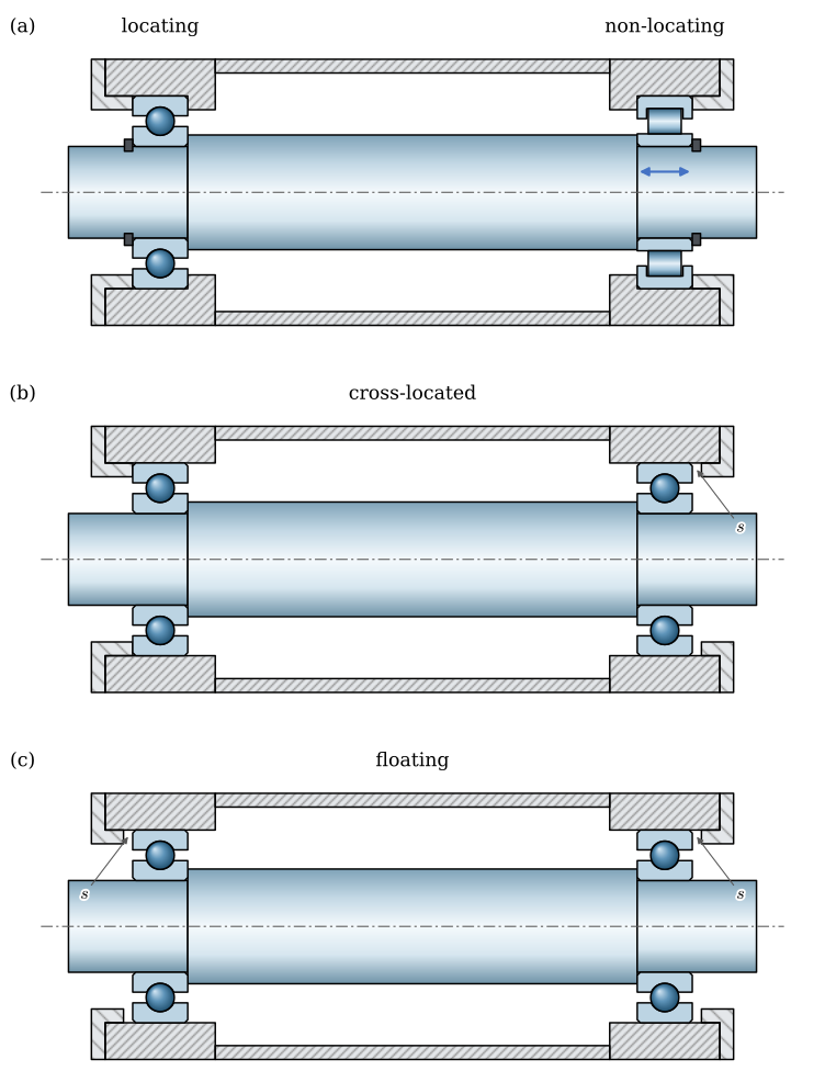
In practice the housing and the bearings give way long before the shaft is compressed by 50 kN: the force goes into the bearings as an axial load they were never meant to carry, and the internal clearance of a small ball bearing, a few hundredths of a millimetre, is used up after a fraction of the growth. The bearings run hot, which makes the shaft grow more, and fail. A shaft is therefore located axially at one place only, and every bearing arrangement is a way of doing that. Figure 9.9.4 shows the three patterns on the same shaft.
Figure 9.9.4: Three ways to locate a shaft. (a) A locating deep groove ball bearing on the left, both rings held in both directions, and a non-locating cylindrical roller bearing (NU) on the right, inside which the shaft can slide. (b) Cross-located: each bearing holds the shaft in one direction, against its end cover, with the axial clearance \(s\) at one end. (c) Floating: clearance \(s\) at both ends, the shaft located by something else.
The locating and non-locating arrangement of Figure 9.9.4 (a) is the general solution. The locating bearing holds the shaft in both axial directions: its inner ring is clamped between a shaft shoulder and a retaining ring, its outer ring between a housing shoulder and an end coversv. lock. It carries the radial load at its end and the whole axial load. The non-locating bearing carries radial load only and lets the shaft grow. Either the bearing allows axial movement inside itself, as the cylindrical roller bearings NU and N, the needle roller bearing and CARB do, and then both its rings can be held tight; or a deep groove or spherical roller bearing has its outer ring fitted loose in the housing, so that the whole bearing slides in its seat. The second way is cheaper, but a ring that slides must be the one that is stationary relative to the load (Section 9.9.4). The arrangement works for any shaft length and any temperature difference.
The cross-located arrangement (b) is for short shafts. Each bearing holds the shaft in one direction: the shaft shoulders push the inner rings outwards, the end covers hold the outer rings from outside. Pushed to the left, the shaft is held by the left bearing; pushed to the right, by the right one. Some axial clearance \(s\), a few tenths of a millimetre, is left at assembly for the shaft to grow into, and the arrangement works as long as the growth of 9.9.1 stays below it. With angular contact or tapered roller bearings the same arrangement is called adjusted: the clearance is set with shims or a nut to a small value, zero, or a preload (Section 9.9.3.1).
The floating arrangement (c) has clearance at both ends, so the shaft can move a distance \(s\) in either direction and is located by something other than its bearings. The pinion of a herringbone gear pair is the classic case: the V of the teeth centres the pinion on the wheel, and its bearings must let it.
Back to back and face to face
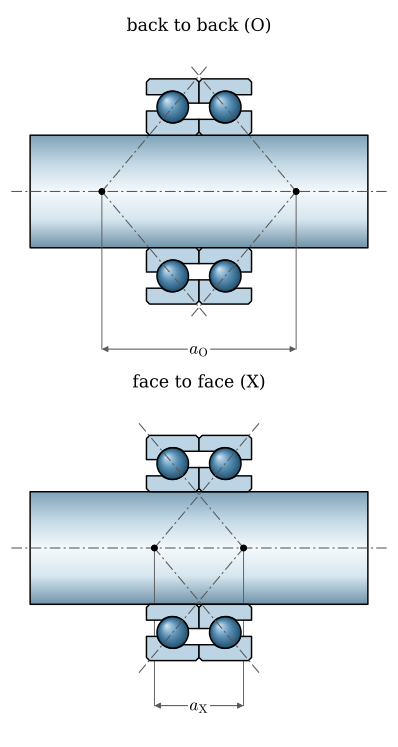
A pair of angular contact or tapered roller bearings can be mounted in two ways (Figure 9.9.5). The load line through each rolling element, carried on to the shaft axis, meets it at the bearing’s pressure centre; that is where the bearing’s reaction acts on the shaft. Back to back, in an O arrangement, the load lines diverge towards the axis and the pressure centres lie outside the pair, a distance \(a_\mathrm{O}\) apart. Face to face, in an X arrangement, they converge and the pressure centres lie between the bearings, at the smaller distance \(a_\mathrm{X}\).
Figure 9.9.5: A pair of angular contact ball bearings with a contact angle of 40°: back to back (O) above, face to face (X) below. The load lines carried to the shaft axis meet it at the pressure centres (dots), the distance \(a\) apart.
The distance \(a\) is the lever arm against a tilting moment on the shaft. With the same two bearings in the same space, the O arrangement resists a moment with forces \(a_\mathrm{O}/a_\mathrm{X}\) times smaller than the X arrangement, about twice as small in Figure 9.9.5, and the shaft tilts less: the O arrangement is stiff. It is the choice where a moment must be carried in little axial length, as in a machine tool spindle (Example 3) or a car’s wheel hub, whose bearing unit is a double-row angular contact bearing mounted back to back. The X arrangement is less stiff against tilting and less sensitive to misalignment, and its outer rings are easy to adjust from the covers, which suits a gear shaft with the gear between the bearings (Example 4).
Holding the rings
Which ring is tight
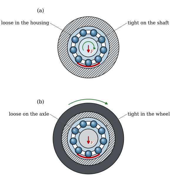
A ring that turns relative to the load must sit tight on its seat. The load passes through the ring at the point that faces it, and if that point moves around the ring at every revolution, a loose ring rolls along its seat like a wheel on a slightly larger road, a little further each turn. This creep wears and polishes the seat (fretting) and eventually lets the ring spin. A ring that is stationary relative to the load sees it at the same point all the time, and it may be a sliding fit.
Figure 9.9.6: Seen along the shaft. (a) The shaft turns, the load \(F\) keeps its direction: the load sweeps round the inner ring, which needs the tight fit, and stays on one zone of the outer ring (red), which may sit loose in the housing. (b) A wheel turns on a fixed axle: the load sweeps round the outer ring, which sits tight in the wheel, and the inner ring may slide on the axle.
Figure 9.9.6 shows the two cases. A shaft that turns under a load of fixed direction, a motor driving a belt, a gear shaft, a spindle, has rotating inner rings: tight on the shaft, loose in the housing. A wheel or pulley that turns on a fixed axle, a skateboard wheel, a belt idler, a car’s non-driven wheel on its stub axle, has rotating outer rings: tight in the wheel, loose on the axle. As a starting point, a rotating shaft under moderate load is ground to k6 or m6 and the housing bored to H7; the ISO fits of the shaft–hub chapter apply, and the makers’ tables refine the choice for load, size and ring material [2]. A tight fit expands the inner ring and shrinks the outer, and both reduce the internal clearancesv. lagerglapp of the bearing; a warm inner ring does the same. Electric motors therefore often use bearings with the larger clearance class C3.
Holding them axially
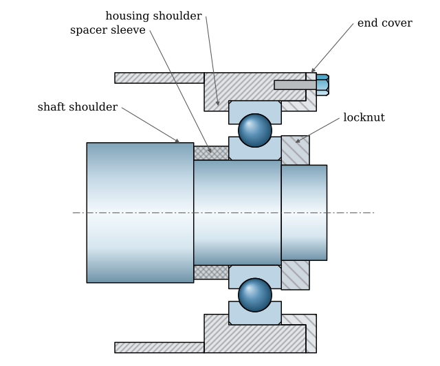
A locating bearing has both rings held axially in both directions, a non-locating bearing has them held where the arrangement needs it. Figure 9.9.7 shows the usual parts. The inner ring sits against a shaft shouldersv. axelansats, directly or through a spacer sleeve, and is clamped from the other side by a locknut with a tab washer or, for smaller axial loads, a retaining ringsv. spårring in a groove (the circlips of Figure 9.9.4). The outer ring sits against a shoulder in the housing and is held by an end cover. The shoulders must be high enough to carry the ring’s face but low enough to leave room for a puller; the catalogues give the abutment diameters for each bearing.
Figure 9.9.7: A deep groove ball bearing at the end of a shaft. The inner ring is clamped between a spacer sleeve, which bears on the shaft shoulder, and a locknut; the outer ring between the housing shoulder and a bolted end cover.
A bearing comes open, shielded (suffix Z or 2Z, a metal shield with a small gap) or sealed (2RS, rubber lips that touch the inner ring). Shielded and sealed bearings are greased for life and need nothing more; open bearings run in oil from a gearbox or are regreased, and the housing then carries the seal.
Rotating shafts in practice
The examples that follow apply the three decisions of the previous sections (type, axial location, fits) to machines in which the load and the application settle them.
Example 1: An electric motor
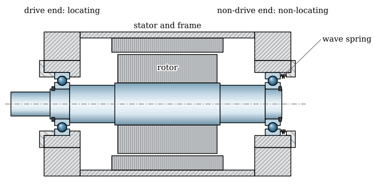
An electric motor (Figure 9.9.8) carries its rotor on two deep groove ball bearings in the end shields. The drive end, where the shaft leaves the motor, is the locating bearing: its outer ring is held between a lip of the end shield and a cover, and its inner ring between the shaft shoulder and a retaining ring. At the non-drive end the outer ring sits in a closed pocket of the end shield with a loose fit, and a wave spring presses it axially. The rotor heats up more than the frame, and the shaft grows towards the non-drive end, where the outer ring slides. The spring also loads both bearings lightly in the axial direction, which keeps the balls rolling instead of skidding when the radial load is small and quiets the motor.
Figure 9.9.8: Example 1: an electric motor. The drive end (left) locates the rotor; at the non-drive end the outer ring may slide in its pocket, pushed by a wave spring.
The belt or coupling load keeps its direction while the shaft turns, so the inner rings are tight on the shaft and the outer rings are a sliding fit in the end shields: at the non-drive end the sliding fit is what lets the shaft grow, and at the drive end the cover holds the ring axially.
Example 2: A skateboard wheel
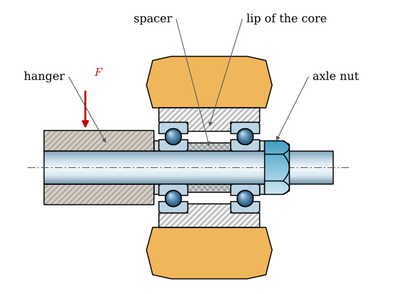
A skateboard or inline skate wheel runs on two 608 bearings, 8 mm bore, 22 mm outside diameter and 7 mm wide, pressed into the wheel’s core from each side against a lip between them (Figure 9.9.9). The load comes from the axle and keeps its direction while the wheel turns, so this is the case of Figure 9.9.6 (b): the outer rings are tight in the wheel and the inner rings slide on the axle. The two bearings are cross-located; in a turn the sideways force on the wheel goes through the lip into one outer ring or the other.
Figure 9.9.9: Example 2: a skateboard wheel on two 608 bearings. The axle nut clamps the inner rings, the spacer and the washers against the hanger as one stack; the outer rings sit in the core against its central lip.
The spacer between the inner rings is the detail that matters. The axle nut must be tightened to hold the wheel on, and without a spacer it would push the two inner rings towards each other while the lip holds the outer rings apart: an axial load on both bearings that grows with every turn of the nut, and a wheel that does not spin. With the spacer, the nut clamps the inner rings, the spacer and the washers as one solid stack against the hanger, and the bearings see no load from it. The wheels and hubs of the RC car are built the same way, with smaller bearings.
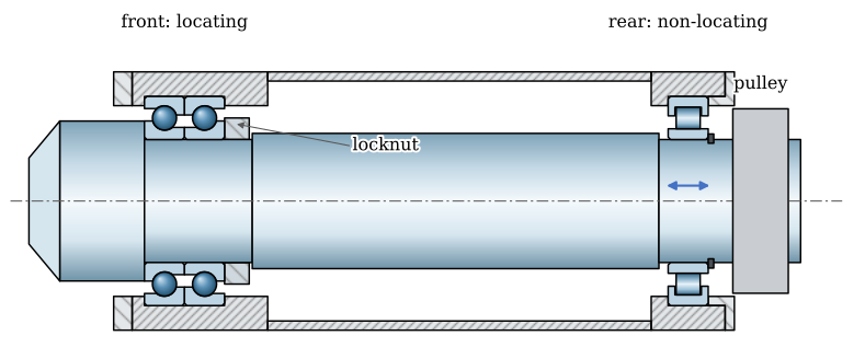
Example 3: A machine tool spindle
A machine tool spindle (Figure 9.9.10) must hold the tool where the program puts it, so its stiffness enters the accuracy of the part directly. The front end, at the tool, carries a pair of angular contact ball bearings back to back, preloaded by the locknut that clamps their inner rings together. The O arrangement gives the large pressure centre distance of Figure 9.9.5 against the moment from the cutting force, and the preload removes the clearance, so the spindle moves only by the elastic deformation of the balls and raceways. The rear end carries a cylindrical roller bearing NU, non-locating.
Figure 9.9.10: Example 3: a machine tool spindle. Front: two angular contact ball bearings back to back, preloaded, locating. Rear: a cylindrical roller bearing (NU), in which the spindle grows towards the belt pulley.
The spindle heats up at high speed and grows. Because it is located at the front, it grows backwards, towards the pulley, and the position of the tool does not change. A designer who located it at the rear would see the tool move by the thermal growth of 9.9.1 as the machine warms up, tenths of a millimetre on a spindle that should hold hundredths.
Example 4: A helical gear shaft
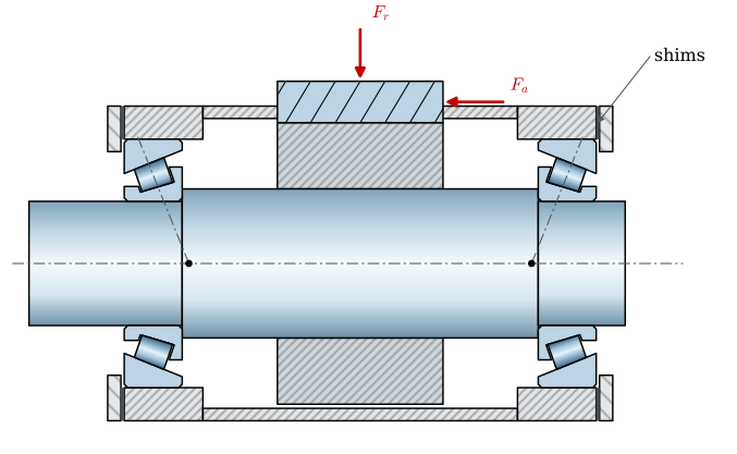
A helical gear pushes its shaft axially with the force \(F_a = F_t\tan\beta\) from the helix angle \(\beta\) (herringbone gears), in one direction or the other depending on which way the gear drives. The shaft of Figure 9.9.11 is short, the radial and axial loads are both large, and the tapered roller bearing carries both. Two of them face to face form an adjusted, cross-located arrangement: each takes the axial force in its own direction.
Figure 9.9.11: Example 4: a helical gear on a shaft carried by two tapered roller bearings face to face (X). Shims under the end covers set the axial clearance or preload. The load lines meet the axis at the pressure centres (dots), between the bearings.
The cups are pushed in by the end covers, and the shims under the covers set the axial play, ground to the value the gearbox maker specifies. The arrangement has no non-locating bearing, so it relies on the shaft being short: the growth of 9.9.1 over 100 mm at 30 K is 0.04 mm, which the adjustment allows for.
Example 5: A long shaft in pillow blocks
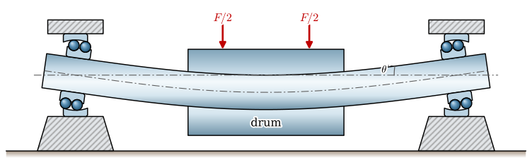
A conveyor drum turns on a long shaft whose bearings sit in pillow blocks, cast housings bolted to the conveyor frame (Figure 9.9.12). The shaft bends under the belt pull, and the frame and the two blocks are never exactly in line. At a support, a shaft carrying a central load \(F\) on the span \(L\) slopes by \(\theta = FL^2/(16EI)\). For a 40 mm shaft carrying 5 kN in the middle of a 1 m span:
Code
F_c, L_c, d_c =5e3, 1000.0, 40.0# belt pull [N], bearing distance and shaft diameter [mm]I_c = np.pi*d_c**4/64# second moment of area [mm^4]theta_c = F_c*L_c**2/(16*E_st*I_c) # slope at each support [rad]
Forty minutes of arc is several times what a deep groove ball bearing tolerates, and the error of mounting the blocks comes on top. Self-aligning ball bearings, or spherical roller bearings for heavier loads, let the inner ring tilt with the shaft while the outer ring stays in its housing. One of the two pillow blocks gets locating rings on both sides of the outer ring, the other none, so that one bearing locates the shaft and the other floats in its block.
Figure 9.9.12: Example 5: a conveyor drum shaft on self-aligning ball bearings in pillow blocks. The bending is exaggerated: the inner rings and balls of each bearing tilt with the shaft by \(\theta\), the outer rings stay in their housings.
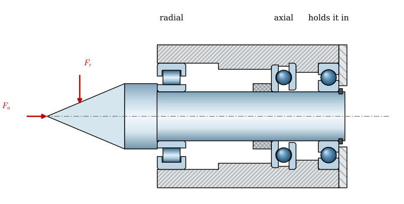
Example 6: The live centre of a lathe
A long workpiece in a lathe is supported at its free end by a centre in the tailstock, and a live centre turns with the work (Figure 9.9.13). The tailstock pushes the centre into the work, so the centre carries a large axial force \(F_a\) as well as the radial force \(F_r\) from the cutting. The two loads are given to different bearings: a cylindrical roller bearing close to the point takes the radial load where it enters, a thrust ball bearing behind it takes the axial load, and a deep groove ball bearing at the rear holds the spindle in its housing and supports it radially.
Figure 9.9.13: Example 6: the live centre of a lathe tailstock. The workpiece pushes the centre in with \(F_a\) and loads it radially with \(F_r\).
The same division of labour carries larger machines. A crane or an excavator turns on a slewing ring, a single four-point contact or crossed roller bearing of a metre or more in diameter that carries the weight, the radial load and the tilting moment of the boom at once. A ship’s propeller pushes the ship with its shaft, and the thrust goes into the hull through a spherical roller thrust bearing, while ordinary radial bearings carry the weight of the shaft along its length.
Linear bearings
A linear bearingsv. linjärlager guides a carriage along a straight line, and the questions are those of the rotating shaft: which freedoms are removed, by which bearing, and what happens when the parts are not exactly where the drawing puts them.
Example 7: A 3D printer carriage
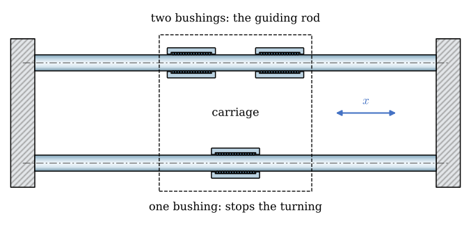
The print head of many 3D printers runs on two hardened 8 mm rods in LM8UU ball bushingssv. linjärkullager, 8 mm bore, 15 mm outside and 24 mm long, in which rows of balls roll on the rod and return through channels in the sleeve. Figure 9.9.14 shows the carriage from above with three bushings: two on the upper rod, one on the lower.
Figure 9.9.14: Example 7: the carriage of a 3D printer seen from above, on two 8 mm rods and three LM8UU ball bushings. The two bushings on the upper rod guide the carriage along it; the one on the lower rod stops it from turning about the upper rod.
Two bushings on one rod remove four freedoms: the two translations across the rod and the two tilts. The carriage can still slide along the rod and turn about it, and the single bushing on the second rod stops the turning. Three bushings do the job exactly. A fourth, on the lower rod, would also try to fix the distance between the rods, and two rods are never exactly parallel: over the travel the carriage would be forced to follow both, the bushings would bind at one end, and the motor would skip. This is the axial location of a shaft again: one guide locates, the other only supports. Printers that use four bushings get away with it through the flexibility of the printed carriage and the rods, and a stiffer design lets the second rod’s bushing float sideways in a slot.
The rods must be hard. The balls of a bushing touch the rod at points, as in a ball bearing, and on a soft rod they roll grooves into it within hours; LM8UU rods are induction hardened and ground.
Where to pull
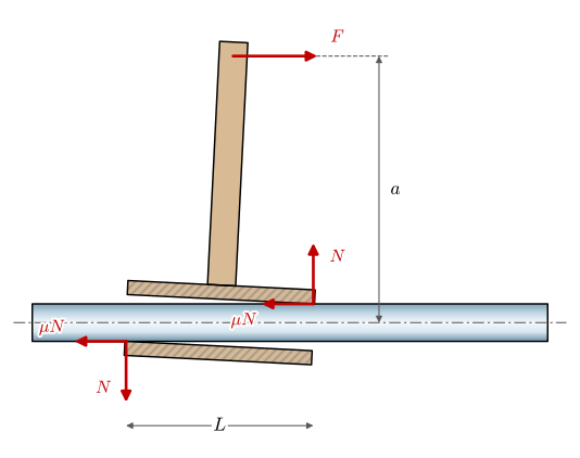
Three bushings fix where the carriage goes, but not how hard it is to push. The belt pulls the carriage at some distance \(a\) from the guiding rod, and that force has a moment about the bushings. Figure 9.9.15 treats the two bushings on the guiding rod as one sleeve of length \(L\), the distance between their outer ends, pushed along the rod by \(F\) at the offset \(a\). The sleeve tilts within its clearance until it bears on the rod at both ends, and the two normal forces \(N\) form the couple that balances the moment of \(F\):
\[
N L = F a
\]
Figure 9.9.15: Example 7: the bushings on the guiding rod drawn as one sleeve of length \(L\), pushed along the rod by \(F\) at the offset \(a\). The sleeve tilts in its clearance (exaggerated) and bears on the rod at its two ends with \(N\); friction \(\mu N\) acts at both against the motion.
Friction at the two contacts resists the motion with \(2\mu N\), so the sleeve moves only if \(F > 2\mu N = 2\mu F a/L\). The force cancels, and what remains is a condition on the geometry alone: the sleeve slides under any force if
\[
\frac{a}{L} < \frac{1}{2\mu}
\tag{9.9.2}\]
and jams under any force if the ratio is larger. Above the limit a stronger motor only presses the sleeve harder against the rod. The clearance does not appear in 9.9.2, so tighter tolerances do not cure jamming; they only make the sleeve tilt less before it locks. The cures are a shorter arm, a longer bearing, or less friction. Makers of plain linear bearings state the rule as a ratio of 2:1, which is 9.9.2 for \(\mu = 0.25\)[3].
The friction coefficient decides everything. A recirculating ball bushing runs at about \(\mu = 0.001\)[4], a polymer liner on a steel rod at 0.06 to 0.18 [5], and polymer bushings are a popular swap on printers because they are quiet. We take the X carriage of Figure 9.9.14, with the belt halfway between the rods, and the bed of a printer whose Z axis is driven by one lead screw at the bed’s edge, the bed guided by two rods with bushings 45 mm long and its far edge 200 mm away:
Code
mu = {'ball bushing': 0.001, 'polymer bushing': 0.18}geometry = {'X carriage': (25.0, 68.0), 'Z bed': (200.0, 45.0)} # (a, L) [mm]ratio = {k: a/L for k, (a, L) in geometry.items()}limit = {k: 1/(2*m) for k, m in mu.items()} # @eq-br-jam
The X carriage is far inside both limits and runs on either bushing. The Z bed is far inside the limit of ball bushings and beyond that of polymer ones: converted to polymer bushings, it jams. The force on the bed is the lead screw’s, at the bed’s edge, but the weight of the bed and the print hangs on the far side too, and the moment of both is what the bushings must carry.
A second rule follows from the same statics. The friction of a carriage is the sum of the friction at its bushings, \(\mu\) times the normal load on each, and the resultant of those forces lies between the rods, nearer the one that carries more. A belt attached on that line pulls the carriage without any moment, and the guides carry no couple from the drive at all. Most printer carriages clamp the belt between the rods, close to it.
Rattle or bind
The LM8UU has clearance, a few hundredths of a millimetre between balls, sleeve and rod, and the print head moves by that much when the belt reverses. The way to remove play is a tighter bushing or a preload, and either brings back the over-constraint of the four bushings: the rods are not exactly parallel, the carriage is forced to follow both, and it binds. This is the dilemma Ryan Norbauer describes for keyboards (Example 8): free movement, no play and tolerance to variation in the parts, of which a design gets two [6]. The way out is to take the steps in order: first constrain the carriage exactly, then remove the play in the contacts that remain.
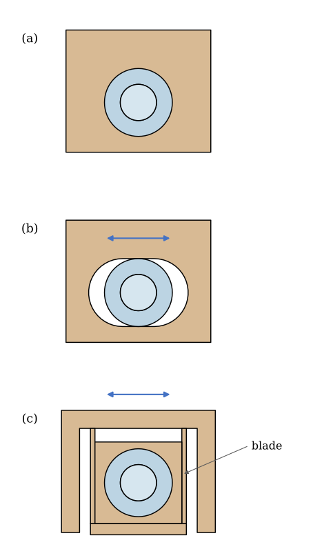
Figure 9.9.16: Example 7: three ways to hold the bushing on the second rod, seen along the rods. (a) Rigid in the carriage: with tight bushings, the carriage binds wherever the rods are not parallel. (b) In a slot: free across the rods, tight in the vertical direction. (c) On a printed parallel-blade flexure: free across the rods with no clearance at all.
Figure 9.9.16 shows the bushing on the second rod held three ways. Held rigidly (a), it fixes the distance between the rods at the carriage. In a slot (b), it is free across the rods and held vertically, so it stops the turning about the guiding rod and nothing else: it is the non-locating bearing of 9.9.1, moved to a linear guide. A slot still has clearance in the vertical direction, however small. The printed flexure (c) has none. Two thin blades carry the bushing holder; across the rods the holder moves by bending the blades, and vertically it is held by the blades in tension and compression, in which they are stiff. Each blade bends as a beam fixed at one end and guided at the other, with the stiffness \(12EI/l^3\). For blades of PETG 0.8 mm thick, 10 mm wide along the rod and 20 mm long, taking \(E \approx 2\) GPa for the printed material:
Code
E_petg, t_bl, w_bl, l_bl =2000.0, 0.8, 10.0, 20.0# [MPa], blade thickness, width, length [mm]I_bl = w_bl*t_bl**3/12k_flex =2*12*E_petg*I_bl/l_bl**3# two blades in parallel [N/mm]F_side = k_flex*0.2# rods 0.2 mm out of parallel [N]
The flexure is soft across the rods:
\[ \begin{aligned}k &=2.56~\text{N/mm},\quad F = k \cdot 0.2~\text{mm} =0.512~\text{N}\end{aligned} \]
Rods that are 0.2 mm out of parallel over the travel push the carriage sideways with half a newton, which the guiding rod’s bushings carry without noticing. The price of a flexure is that it is a spring: its force grows with deflection, so it suits small movements, and a printed blade creeps and fatigues. With the guide exactly constrained, the remaining play can then be removed by preload, a spring or an eccentric that presses the remaining contacts together, like the wave spring of Example 1 or the eccentric spacer of a V-wheel.
Example 8: The space bar of a keyboard
A keyboard’s space bar is the extreme case of Example 7. It is pressed anywhere along its length, and a stabilizer must make both ends go down together: a wire runs across under the bar and is held at each end in a plastic slider guided in a housing. The two stems are about 100 mm apart and guided over a few millimetres of travel, so a press at one end puts a ratio \(a/L\) of tens on the slider’s guide, far beyond the limit of 9.9.2 for plastic on plastic. Commercial stabilizers work because their parts are loose, and they rattle for the same reason. Enthusiasts take them apart and fill them with thick grease, which damps the noise but has to be applied by hand and seeps away.
Figure 9.9.17: Example 8: Ryan Norbauer on the stabilizer of his Seneca keyboard, from 8:41 (the failed experiments) through 20:18 (the pin joint design) [6].
Ryan Norbauer, who designs keyboards, set out to build a stabilizer that neither rattles nor needs grease, and the video tells how (Figure 9.9.17). His first attempt was precision-machined stems in polymer bushings with tight fits: the key went down and did not come back up. It jammed, as 9.9.2 predicts. Tightening the fits in the plastic parts made them bind; loosening them brought the rattle back; and the space bars of different makers differ in stem spacing by up to a millimetre, which every fit must accept. He summarises it as the choice of two out of free movement, good acoustics and tolerance to variation.
The engineering consultants he brought in, the Danish firm RD8, diagnosed over-constraint: the standard stabilizer guides its slider on several widely spaced rails, redundant contacts that turn every variation in the parts into force. Their demonstrator is the carriage of Example 7: two carriages on two rods each, one with every hole a close fit, the other with one hole made deliberately too large so that only three contacts remain. With the rods slightly out of parallel, the first binds and the second runs. Their redesign followed the order of Example 7. They replaced the rails by one short tongue and groove, which can be held to a close clearance because the dimension is small, and which leaves the slider free in the direction where the space bar’s width varies: constrained only where it must be. With the over-constraint gone, they added a small V-spring of spring steel that presses lightly on the wire and stops it rattling, without making anything bind. A fully compliant stabilizer, all flexures, was rejected because its force would rise with the key’s travel and the key would feel soft. The final design is a linkage of ground pins, which hold their size to an order of magnitude better than moulded faces and roll instead of slapping flat faces together, with small preload beams where clearance remains.
The design is extravagant for a keyboard, and the story took Norbauer years. Its lessons are the ones of this chapter: count the constraints before tightening the tolerances, hold small dimensions tight and let the large ones float, and add preload only once nothing is constrained twice.
Example 9: A ball screw axis
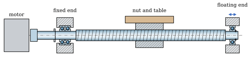
A CNC machine drives each axis with a ball screw, a screw whose nut runs on recirculating balls, and the screw is a shaft that needs bearings (Figure 9.9.18). The motor end is the fixed end: a pair of angular contact ball bearings back to back takes the axial force of the cut in both directions, preloaded so that the table does not move when the force reverses. The other end is the floating end: a deep groove ball bearing whose outer ring may slide in its housing. The friction in the nut heats the screw, the screw grows, and the floating end takes the growth. Hobby CNC machines buy the two ends as support units, sold as BK (fixed) and BF (floating).
Figure 9.9.18: Example 9: a ball screw axis. The fixed end at the motor holds the screw axially with two angular contact bearings back to back; at the floating end a deep groove ball bearing slides in its housing.
The table itself rides on profile rails (Section 9.9.6.4), hardened rails with carriages in which balls or rollers recirculate. A carriage on a profile rail is preloaded, takes loads and moments in every direction, and is far stiffer than a bushing on a rod. A table on two rails has the over-constraint of the printer carriage, and the remedy is the same idea: one rail is mounted as the reference, pushed against a ground shoulder of the machine bed, and the second rail is aligned to the first through the table instead of to the bed.
Older and simpler machines slide. The bed of a manual lathe has ways of cast iron, scraped flat by hand, on which the carriage slides with a film of oil, and its cross slide moves in a dovetail whose play is taken up by a tapered gib strip that the machinist adjusts with screws. Sliding ways damp vibrations better than rolling ones and survive chips and crashes. At the other end of the range, many hobby printers and routers run on V-shaped wheels with ball bearings inside, rolling in the grooves of an aluminium extrusion; one wheel on each side sits on an eccentric spacer, and turning it presses the wheels against the extrusion and removes the play.
Profile rail guides
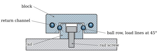
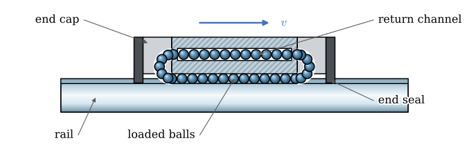
A profile rail guide is a ball bearing unrolled along a straight line. A hardened steel rail carries ground grooves along both sides, and a block runs on it on rows of balls (Figure 9.9.19). The balls cannot run out of the block’s length, so they recirculate (Figure 9.9.20): they carry the load on the straight between rail and block, turn round in a plastic end cap, run back through a channel in the block and turn again at the other end. Seals at both ends wipe dirt off the rail. The miniature MGN series that hobby printers and small CNC machines use has a 12 mm wide rail in size 12 and a block 27 mm wide and 35 mm long [7].
Figure 9.9.19: A miniature profile rail guide in MGN12 proportions, cut across the rail. Each of the two ball rows runs in Gothic-arch grooves and carries load along two load lines at 45°, so the block takes load in every direction across the rail. The returning balls run in channels in the block.
Figure 9.9.20: The block cut along one row of balls. The balls carry the load on the lower straight, turn round in the end caps and return through a channel in the block as it moves with \(v\); the end seals wipe the rail.
The grooves have a Gothic-arch profile, two arcs meeting in a point, so every ball touches the rail at two points and the block at two, and the load lines cross at 45°. Two rows with two load lines each carry load downwards, upwards and sideways, and because the rows lie apart, a single block also carries the three moments about its own axes: the roll about the rail and the pitch and yaw across it. An MGN12C block is rated at \(C = 2.84\) kN, \(C_0 = 3.92\) kN, a static roll moment of 25.5 N·m and pitch and yaw moments of 13.7 N·m each; the longer MGN12H nearly triples the pitch and yaw moments to 36.3 N·m, because its ball rows are longer [7]. One block on one rail is therefore a complete guide, exactly constrained in the sense of Example 7: it removes five freedoms and leaves the travel along the rail. The dynamic rating of a linear guide is given for 50 km of travel, and the life follows from 9.9.4 with the revolutions replaced by distance: \(L = (C/P)^3 \cdot 50\) km.
The load capacity is rarely what decides. A print head of 0.4 kg accelerated at 10 m/s² with its centre of mass 40 mm from the rail puts a moment of 0.16 N·m on the block, about 1 % of the MGN12C’s rating. Profile rails are chosen for their stiffness and for having no play. The block is sold in three preload classes: ZF with a clearance of 4 to 10 µm, Z0 with between no clearance and a very light preload of 3 µm, and Z1 with a light preload of up to 0.02 \(C\)[7]. Preload is the remedy of Section 9.9.6.1.2 built into the bearing: the balls are slightly oversized, so the block has no play to rattle in, and a Z0 MGN12C deflects by about 1 µm for every 44 N.
The price is accuracy of the mounting. A preloaded block on a rail is stiff because it cannot give, so it also cannot give when the rail is bolted to a surface that is not flat, and the error turns into force in the balls and friction in the travel. For the MGN12 the maker asks for a mounting surface flat to 0.05 mm over 200 mm with ZF and Z0 blocks, half that with Z1, and for two rails on one surface, parallel to within 9 µm [7]. Machine tools grind their reference surfaces to that. A printer frame of aluminium extrusions is not made to it, and the builders who succeed choose ZF or Z0 blocks, bolt one rail per axis and align it against a straight edge instead of trusting the extrusion. A steel rail on an aluminium beam also forms a bimetal: aluminium expands by about \(23 \cdot 10^{-6}\) per kelvin and steel by \(12 \cdot 10^{-6}\), so a 300 mm rail on a beam that warms by 20 K is held to a beam that has grown 0.07 mm more than the rail. The screws carry the difference, and the beam bows slightly; the rail screws are spaced 25 mm apart along the rail, which keeps the shear on each small.
The photograph that prompts most questions about these guides shows a block next to its rail and a scatter of loose balls. The MGN blocks of the original maker hold their balls in with a retaining wire [7], but many cheap copies do not, and a block slid off the end of its rail drops its balls on the floor. Blocks are shipped on a plastic dummy rail, and they move from that rail onto the steel one end to end, without a gap.
Plain bearings
A plain bearing lets the shaft slide in a bore. In its simplest form it is a bushing, a sleeve pressed into the housing: sintered bronze with oil held in its pores, a steel shell with a thin layer of PTFE, or a polymer that runs dry. Bushings are cheap, small, quiet and insensitive to shock and dirt, and they suit slow, oscillating or intermittent motion: hinges, levers, pivots, the joints of a suspension, the guide pins of a mould.
A bushing is checked against the pressure and the sliding speed. A shaft of diameter \(d\) carrying the radial load \(F\) in a bushing of length \(B\) presses on the projected area \(dB\), and its surface slides at the speed \(v = \pi d n\) for \(n\) revolutions per second. The heat generated by friction per unit of projected area is the friction coefficient times
\[
p\,v = \frac{F}{dB}\,\pi d n
\tag{9.9.3}\]
The heat must leave through the housing, and the temperature the bushing reaches limits the product \(pv\); the maker gives the largest \(p\), the largest \(v\) and the largest \(pv\) for each material [8, Ch. 12]. A dry polymer bushing runs at a fraction of the \(pv\) an oil-filled bronze bushing takes.
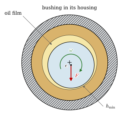
A journal bearing in a combustion engine or a turbine works differently (Figure 9.9.21). The shaft turns in a bore a little larger than itself, the bore full of oil, and the load pushes the shaft off centre by the eccentricity \(e\). The turning shaft drags oil into the narrowing gap, the oil cannot escape fast enough, and the pressure it builds carries the shaft on a film a few micrometres thick at its thinnest, \(h_\mathrm{min}\). Metal never touches metal while the shaft runs, so a hydrodynamic bearing in clean oil lasts almost indefinitely. It wears at start and stop, when the speed is too low to build the film, and the bearing materials (white metal, bronze, aluminium alloys) are chosen to survive those moments.
Figure 9.9.21: A hydrodynamic journal bearing seen along the shaft, the clearance exaggerated. The load \(F\) pushes the turning shaft off centre by \(e\); oil dragged into the narrowing gap carries it on a film whose thinnest point is \(h_\mathrm{min}\).
A printed hole is a plain bearing too. A steel pin in a printed bore works as a pivot for a slow, lightly loaded joint, a hinge, a lever, a latch, and igus sells filaments made for printed bushings. It does not work for a shaft that turns continuously under load: the plastic heats up, softens and wears, and a bought bearing in a printed seat is the answer (Section 9.9.8).
Bearings in printed parts
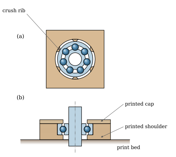
Most bearings in the course’s projects sit in printed parts: wheel hubs, idlers, the supports of a belt-driven shaft. A printed seat cannot be bored to H7, but it can be designed so that the printer’s errors do not matter (Figure 9.9.22).
Figure 9.9.22: A 608 bearing in a printed part. (a) The bore seen along the axis, with six crush ribs that the outer ring flattens as it is pressed in. (b) The part cut through the axis, printed with the axis vertical: the shoulder is printed first, on the bed, and a printed cap holds the bearing from above.
The bore is printed with its axis vertical, so that every layer is a round hole; a horizontal bore droops at the top. A plain round hole cannot be printed to the interference a press fit needs, so the bore is made larger than the bearing and given crush ribs, narrow ridges that the outer ring flattens as it goes in [9]. The ribs give a tight fit over the whole scatter of hole sizes a printer produces. The bearing sits against a shoulder printed on the bed, the flattest and most accurate surface of the part, and a cap screwed into heat-set inserts holds it from the other side. If the outer ring rotates (a wheel, an idler), the ribs give it the tight fit of Section 9.9.4; the inner ring then slides on a smooth pin or the unthreaded shank of a bolt, and a spacer between two bearings takes the clamping force as in Example 2.
Slant 3D, who run a print farm, show the same family of features in a short video (Figure 9.9.23). A horizontal hole gets a point at its top so that the layers never have to bridge it; a blind hole gets a chamfer at its mouth that guides the part in. For a press fit, the hole is drawn at the true diameter and given relief cuts that let its wall spread, and taken all the way round, the reliefs become crush ribs. For a part that is taken out and put back, such as a pin in a jig, they use grip fins: thin flexible lips round the hole, a little smaller than the pin, that bend as it goes in and hold it with the same force every time [10]. Grip fins are the flexure of Figure 9.9.16 (c) applied to a hole: no clearance, and a force set by the stiffness of the fins instead of by the scatter of the print.
Figure 9.9.23: Slant 3D on designing printed holes: points against sagging, lead-in chamfers, relief cuts and crush ribs for press fits from 4:37, and grip fins for reusable fits from 6:13 [10].
Two properties of the plastic limit this. PLA softens at about 60 °C and creeps under a constant load, so a press fit in PLA relaxes over weeks, and next to a hot motor it relaxes faster; PETG and ABS hold better. And a printed part is weakest across its layers, so the cap and the shoulder should carry the axial force in compression or along the layers, never by pulling layers apart. When no bought bearing fits the space or the budget, the printed bearing chapter prints the races themselves.
Bearing life
The catalogue gives two load ratings for each bearing. The basic dynamic load rating \(C\) is the load under which 90 % of a large group of identical bearings survive one million revolutions before the first sign of fatigue. For any other equivalent load \(P\), the rating lifesv. livslängd in millions of revolutions is [11]
with \(p = 3\) for ball bearings and \(p = 10/3\) for roller bearings, and \(L_{10h}\) the same life in hours at \(n\) revolutions per minute. Doubling the load cuts the life of a ball bearing by a factor of eight. A bearing carrying both a radial load \(F_r\) and an axial load \(F_a\) is rated with the equivalent radial load
\[
P = \begin{cases} F_r, & F_a/F_r \le e \\ X F_r + Y F_a, & F_a/F_r > e \end{cases}
\tag{9.9.5}\]
where the factors \(X\) and \(Y\) and the limit \(e\) come from the maker’s tables. For deep groove ball bearings they depend on how large the axial load is compared with the static load rating \(C_0\), through the product \(f_0F_a/C_0\) with a factor \(f_0\) listed for each bearing.
Example 10: The life of a 6210
A 6210 deep groove ball bearing (50 mm bore, 90 mm outside, 20 mm wide) carries \(F_r = 7\) kN and \(F_a = 2.15\) kN at 3000 rpm. The catalogue gives \(C = 37.1\) kN, \(C_0 = 23.2\) kN and \(f_0 = 14\)[2]; the table of \(e\), \(X\) and \(Y\) for normal clearance has rows at \(f_0F_a/C_0 = 1.03\) (\(e = 0.28\), \(Y = 1.55\)) and \(1.38\) (\(e = 0.30\), \(Y = 1.45\)), with \(X = 0.56\), and we interpolate between them.
Code
F_r, F_a, n_rpm =7.0, 2.15, 3000# loads [kN], speed [rpm]C, C_0, f_0 =37.1, 23.2, 14# 6210 from the cataloguek = f_0*F_a/C_0 # where the axial load falls in the tablee = np.interp(k, [1.03, 1.38], [0.28, 0.30])Y = np.interp(k, [1.03, 1.38], [1.55, 1.45])X =0.56P = X*F_r + Y*F_a if F_a/F_r > e else F_r # @eq-br-P [kN]L_10 = (C/P)**3# @eq-br-life, million revolutionsL_10h = L_10*1e6/(60*n_rpm) # hours at n_rpm
The axial load is large enough to count, \(F_a/F_r > e\), and the bearing lasts
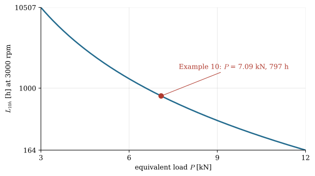
\[ \begin{aligned}F_a/F_r &=0.307,\quad e =0.295,\quad Y =1.47\\P &=7.09~\text{kN}\\L_{10} &=143.0~\text{million rev},\quad L_{10h} =797.0~\text{h}\end{aligned} \]
Eight hundred hours is a month of continuous running, short for a machine that runs all day. Figure 9.9.24 shows how quickly the life changes with the load: at the cube, a 20 % smaller load gives twice the life, and a bearing one size larger, or a roller bearing, is the usual answer.
Figure 9.9.24: The rating life of the 6210 of Example 10 against the equivalent load, 9.9.4 at 3000 rpm. The life falls with the cube of the load.
Why the selector replaces the hand calculation
9.9.4 is the basic rating life, standardised since 1962, and it describes a bearing that is well lubricated, clean and correctly mounted. Real bearings fail of something else first: dirt in the grease, a lubricant too thin at the running temperature, a seat that is not round, water. ISO 281 therefore multiplies the basic life by a life modification factor, \(L_{nm} = a_1 a_\mathrm{ISO} L_{10}\), in which \(a_1\) sets the reliability and \(a_\mathrm{ISO}\) depends on the ratio of the actual to the required oil viscosity, on a contamination factor and on the fatigue load limit of the bearing [11]. The factor spans more than a decade between a clean, well-lubricated bearing and a dirty one, and it is read from diagrams that the makers fit to their own tests. Nobody computes it by hand any more. The makers’ online tools, SKF’s Bearing Select among them, take the loads, speed, temperature, lubricant and cleanliness and return the modified life, the required fits and the lubrication interval. Example 10 shows once where the cube comes from; the next bearing is chosen with the tool.
The same logic answers the student who holds up a 12 × 18 × 4 mm bearing bought online in a bag of ten and asks how much load it takes. Without a maker who has tested it, it has no load rating, and the numbers on the seller’s page are copied from somebody else’s catalogue. Treat it as a bearing of the same size from a known maker with a generous margin, or test it; and where the bearing carries anything that matters, buy the branded one.
TipIn industry: the bearing maker designs with you
Bearing selection in industry runs through the maker’s tools and engineers. The designer enters the loads, speeds and environment into the maker’s selection software (SKF Bearing Select, Schaeffler’s medias, NSK’s and Timken’s equivalents), which returns the type and size, the modified life, the fits of shaft and housing and the lubrication. For anything beyond a catalogue application (a new gearbox, a wind turbine, a rolling mill), the bearing maker’s application engineers review the arrangement and run their own simulations. Mounting follows the maker’s instructions as well: bearings are heated with an induction heater for a shrink fit, never with a torch, and in plants that cannot stop unplanned, the bearings are watched with vibration sensors whose spectra show a raceway defect long before it fails.
Problems
Problem 1: A long fan shaft. A fan shaft has two deep groove ball bearings 600 mm apart, both clamped axially in the housing. In service the shaft runs 40 K warmer than the housing. What happens, and how would you change the arrangement?
Answer:The shaft wants to grow by \(12\cdot10^{-6}\cdot 40\cdot 600 = 0.29\) mm, ten times the internal clearance of the bearings, so both are loaded axially until they fail. Make one bearing locating and the other non-locating: give the second bearing’s outer ring a sliding fit and no cover pressing on it, or replace it by a cylindrical roller bearing NU.
Problem 2: An idler pulley. A belt idler turns on two ball bearings on a fixed bolt. Which rings get the tight fit, and what must sit between the inner rings?
Answer:The pulley and the outer rings turn while the belt load keeps its direction relative to the bolt, so the outer rings are tight in the pulley (crush ribs in a printed one) and the inner rings slide on the bolt’s shank. A spacer between the inner rings lets the nut clamp them without loading the bearings axially, as in Example 2.
Problem 3: A heavier load. The radial load on the 6210 of Example 10 rises to 10 kN, the axial load stays at 2.15 kN. What is the life now?
Answer:\(F_a/F_r = 0.215 < e \approx 0.29\), so \(P = F_r = 10\) kN and \(L_{10} = 3.71^3 = 51\) million revolutions, 284 h at 3000 rpm: a third of the life for 40 % more radial load.
Problem 4: Four bushings. A student builds a printer carriage on two rods with four LM8UU bushings in a stiff aluminium plate, and the carriage jams near one end of the travel. Why, and what are two fixes?
Answer:Four bushings fix the distance between the rods at both ends of the carriage, and the rods are not exactly parallel, so the carriage is forced against the rods where they diverge. Remove one bushing from the second rod, or let the second rod’s bushings float sideways in slotted holes, so that one rod guides and the other only stops the turning.
Problem 5: The wrong end. Why is a lathe spindle located at its front bearings and not at the rear?
Answer:The spindle grows as it warms up. Located at the front, it grows backwards and the chuck stays where it is; located at the rear, the chuck would move forwards by the growth, a tenth of a millimetre or more, and every diameter and length turned while the machine warms up would change.
Problem 6: A cantilevered bed. The Z bed of Example 7 runs on polymer bushings with \(\mu = 0.18\), and its far edge is 200 mm from the guiding rods. How long must the bushing pair be, from outer end to outer end, for the bed not to jam? What else could change?
Answer:9.9.2 asks for \(L > 2\mu a = 2 \cdot 0.18 \cdot 200 = 72\) mm, with margin about 100 mm: two bushings spaced apart on each rod. Otherwise move the lead screw under the bed’s centre of mass, drive the bed from both sides, or go back to ball bushings.
Problem 7: The flexure’s blades. The flexure of Figure 9.9.16 (c) is printed with blades 1.2 mm thick instead of 0.8 mm. How large is the sideways force on the carriage now, for rods 0.2 mm out of parallel? Is it still acceptable?
Answer:The stiffness goes with \(t^3\): \((1.2/0.8)^3 = 3.4\) times stiffer, about 8.6 N/mm, and the sideways force is 1.7 N. Still small against the bushings’ capacity, but it adds friction at the guiding rod; thinner, longer blades keep it lower.
Further reading
The SKF catalogue Rolling bearings[2] is the practical reference for the bearing types, arrangements, fits, abutment dimensions and the life calculation, with many drawings of arrangements like those of this chapter. Harris and Kotzalas [12] treat the contact mechanics, fatigue and lubrication behind the ratings. Budynas and Nisbett [8, Ch. 11 and 12] cover rolling bearing selection and the hydrodynamic theory of journal bearings. ISO 281 [11] defines the dynamic load rating and the modified life. For bearing seats in printed parts, Rahix’s design rules [9] give the crush rib and hole dimensions we use, and the printed bearing chapter follows. The ideas of Example 7 and 8, counting constraints, avoiding redundant ones and adding preload only afterwards, are the subject of exact constraint design; Blanding [13] is the readable introduction, Slocum [14] the reference for precision machines, and Howell [15] for compliant mechanisms.
References
[1]
ISO 15:2017 Rolling bearings – Radial bearings – Boundary dimensions, general plan. Geneva, Switzerland: International Organization for Standardization; 2017.