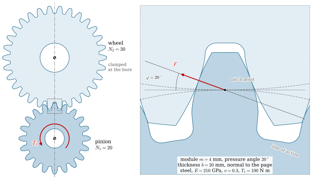
Two steel gears of 20 and 30 teeth, module 4 mm and 20 mm wide, transmit 100 N·m (Figure 14.3.1). The gear strength chapter rates them by hand, with Lewis’s root stress and Hertz’s contact pressure, and checks Lewis against a plane finite element model of the pair. That model does not solve the contact. It puts each tooth force where the involute theory says it acts, spreads it over a strip of our choosing, and splits it equally between two pairs of teeth in contact. Each of the three shortcuts can be replaced by mechanics, and Hertz’s theory is the test each replacement has to pass.
Figure 14.3.1: The gears of Example 1 of Gear strength, and the teeth at the pitch point zoomed. The tooth force \(F\) acts along the line of action at the pressure angle; the model treats the gears as plane bodies 20 mm thick, clamped at the bore.
The gears with prescribed tooth forces
The model treats each gear as a plane body of thickness \(b\) in plane stress, clamped at its bore, which takes up the torque as a shaft would. Its displacement \(\bm u\) satisfies the weak form of elastostatics of the torsion model,
\[
\int_\Omega \bm\varepsilon(\bm v) : \bm\sigma(\bm u)\, d\Omega
= \int_\Gamma \bm v \cdot \bm t \, d\Gamma
\quad \text{for all } \bm v
\tag{14.3.1}\]
where the traction \(\bm t\) on the tooth outline \(\Gamma\) is the tooth force. For a pinion angle \(\theta_1\), the contact points lie on the line of action one base pitch apart, and each pair whose point lies between the tip circles carries \(F\), or \(F/2\) when two pairs are in contact, along the line of action. On each flank the force is spread as a semi-elliptic pressure over a strip of half-width \(a_s = 0.4\) mm,
the shape of a Hertz contact pressure, with \(s\) along the flank.
The width of the strip is our choice, and the true contact area is not. Hertz’s theory, 9.6.5, gives the true strip from the radii of curvature of the two involutes at the contact point, \(\rho = r\sin\varphi\) at the pitch point. With the tooth force of the example, where one pair carries the whole force,
Code
m_g, N_a, N_b, b_g, T_g =4.0, 20, 30, 20.0, 100e3# mm, teeth, mm, N mmE_g, nu_g, a_s =210e3, 0.3, 0.4# MPa, -, mmphi = np.radians(20)r_1, r_2 = m_g*N_a/2, m_g*N_b/2F_g = T_g/r_1/np.cos(phi) # tooth force along the line of actionrho_1, rho_2 = r_1*np.sin(phi), r_2*np.sin(phi)R_eq = rho_1*rho_2/(rho_1 + rho_2)a_H = np.sqrt(8*F_g*(1- nu_g**2)/(np.pi*b_g*E_g)*R_eq)p_H =2*F_g/(np.pi*a_H*b_g) # true Hertz pressurep_s =2*F_g/(np.pi*a_s*b_g) # the model's strip
The true contact is a strip about a fifth of a millimetre wide across the whole face of the tooth, less than a quarter of the strip in the model, and its pressure is more than three times higher. Resolving it would take elements of a few hundredths of a millimetre at every contact point and a contact algorithm. The model therefore shows the contact peak too low on purpose. The stress at the root, a tooth height away, does not depend on how the force is spread, by Saint-Venant’s principle, so the root stresses of Gear strength are not affected.
The gears are meshed with triangles of 0.1 mm along the whole outline, fine enough to resolve the root fillet of radius \(0.3m\): refining further changes the root stress by less than 0.1 %. With quadratic elements the pinion has 350 000 degrees of freedom and the wheel 530 000. The stiffness matrix does not change as the gears turn, only the load does, so each gear’s matrix is assembled and factorized once, and every one of the 120 positions of Figure 9.6.1 needs only a new right-hand side and a back substitution. The heart of the script gears/gears.jl is
A =assemble_matrix((u, v) ->∫(ε(v) ⊙ (σ∘ε(u)))dΩ, U, V)K =lu(A) # once per gearfor θ1in θs # 120 positions of the pinion t =traction(θ1) # strips at the contact points of θ1 rhs =assemble_vector(v ->∫(v ⋅ t)dΓ, V) uh =FEFunction(U, K \ rhs) # a back substitution per frameend
and the whole run, meshing, factorization and 240 solutions, takes about five minutes. The result is the stress animation Figure 9.6.1 of the gear strength chapter, where the root stresses come out about 1.5 times Lewis’s.
plane linear elasticity in Gridap [1,2], plane stress, each gear separately
Scripts
outlines.py writes the tooth outlines with a root fillet of \(0.3m\), gears.jl meshes and solves, render.py draws the frames
Mesh
triangles from gmsh, 0.10 mm along the whole tooth outline, growing to 2 mm from 6 mm inside it; quadratic (six-node) Lagrange elements; refining to 0.07 mm changes the root stress by less than 0.1 %
Size
pinion 83 962 elements, 349 694 degrees of freedom; wheel 126 757 elements, 527 436 degrees of freedom
Boundary conditions
the bore (diameter \(0.3d\)) clamped, \(\bm u = \bm 0\)
Load
no contact solved; at each of the 120 positions the force of each pair in contact acts along the line of action where the involutes cross it, spread over a semi-elliptic strip of half-width 0.4 mm; two pairs share it equally; the centre distance is 0.2 mm larger than standard so that the idle flanks do not touch
Solution
each stiffness matrix assembled and LU-factorized once, about 50 s; then a new load vector and a back substitution per position, about 2 s for both gears; stresses averaged from the elements to the nodes
Contact solved: a cylinder on a plane
A contact condition says that two bodies may touch but not overlap, and that the surfaces push and never pull. Let \(g = y + u_y\) be the gap between a point of a steel cylinder’s surface and a rigid plane at \(y = 0\): the point may not go below the plane, \(g \ge 0\), and the plane pushes on it only where it touches. The penalty method replaces this condition by a stiff spring that acts only on overlap, the traction \(t_y = \kappa\langle -g\rangle\) with \(\langle x\rangle = \max(0, x)\), and adds its work to the weak form of the cylinder,
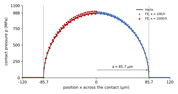
The bracket makes the problem nonlinear, since where the contact ends depends on the solution, and Newton’s method solves it. A large penalty \(\kappa\) allows only a tiny overlap, and the answer stops changing once \(\kappa\) is large enough: going from \(\kappa = 10E/h\) to \(100E/h\), with \(h\) the element size at the contact, moves the results by 0.1 to 0.3 %.
The cylinder has \(R = 10\) mm and carries 133 N per mm of length, the tooth force of the gears per millimetre of face width, in plane strain. A quarter of it is meshed with elements of 2.9 µm at the contact, a thirtieth of the contact half-width.
finite elements
Hertz
half-width \(a_H\) [µm]
85.7
85.7
largest pressure \(p_\max\) [MPa]
989
988
largest von Mises stress [MPa]
553
551
its depth [µm]
61
60
largest shear stress [MPa]
298
297
its depth [µm]
68
67
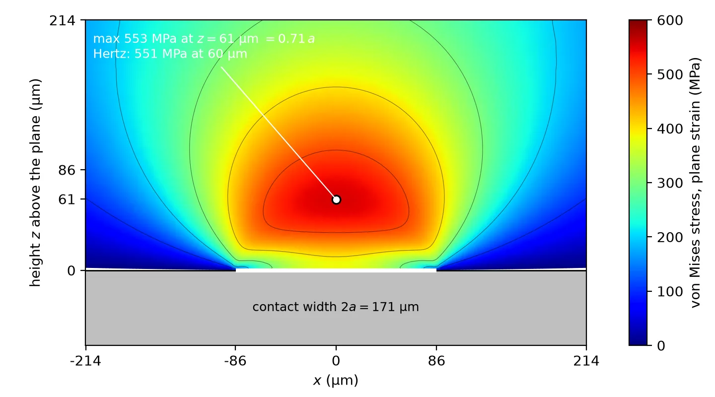
The contact model and Hertz’s theory agree to within a fraction of a percent (Figure 14.3.2). The pressure has the semi-elliptic shape that 9.6.5 assumes, and the largest stress is not at the surface but 0.7 half-widths below it, where the pressure from above and the support from the sides combine into the largest shear. According to [3], the largest shear stress of a cylinder contact is \(0.30\,p_\max\) at the depth \(0.786a_H\), which the model reproduces. This is where pitting starts.
(a) The contact pressure from the penalty model with two penalty stiffnesses (dots), on the Hertz ellipse (line).
(b) The von Mises stress below the contact, with its maximum below the surface.
Figure 14.3.2: A steel cylinder of radius 10 mm pressed on a rigid plane with 133 N/mm, solved as a contact problem with the penalty method in Gridap, against Hertz’s theory.
a quarter of the cylinder, \(R = 10\) mm, plane strain; symmetry (\(u_x = 0\)) on the vertical cut, the displacement prescribed on the horizontal cut, and a secant iteration on that displacement makes the contact force 133.0 N/mm
Mesh
11 545 triangles, 46 390 degrees of freedom, quadratic Lagrange elements; 2.9 µm at the contact, a thirtieth of the half-width, graded outwards
Contact
the penalty traction of 14.3.3 with \(\kappa = 10E/h\) and, as a check, \(100E/h\); Newton’s method with a backtracking line search, 17 steps
Run time
about two minutes on one CPU
True contact strips and load sharing
With the contact model confirming 9.6.5, the gear model can take its strips from it. At each contact point the radii of curvature are the distances along the line of action to the two tangent points of the base circles, and the force of the pair then gives the half-width \(a_H\) and the pressure of 9.6.5. Resolving strips about 0.1 mm wide takes elements of 12.5 µm along the flanks of the teeth that pass through the mesh, about 0.8 million degrees of freedom in the pinion and 1.1 million in the wheel; the stiffness is still factorized once.
The equal split in double contact goes next. Two pairs of teeth in contact must close the same gap: the gears are rigid bodies apart from the deformation of the teeth, so both pairs approach by the same amount \(\delta_0\) as the torque winds the gears up. Let \(C_{ij}\) be the approach of pair \(i\), the movement of the two flanks towards each other along the line of action, under a unit force on pair \(j\); the model computes it with two extra back substitutions per gear. The forces \(f_1, f_2\) on the two pairs then satisfy
\[
\bm C \bm f = \delta_0 \begin{bmatrix} 1 \\ 1 \end{bmatrix}, \qquad f_1 + f_2 = F
\quad\Rightarrow\quad
\bm f = F\,\frac{\bm C^{-1}\bm 1}{\bm 1^{\mathsf{T}}\bm C^{-1}\bm 1}
\tag{14.3.4}\]
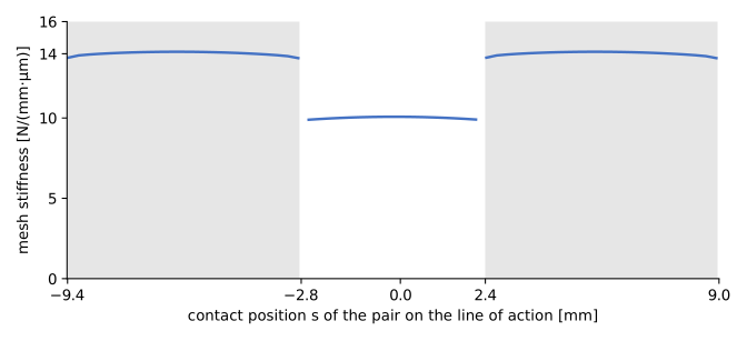
and the mesh stiffness\(k = F/\delta_0\) is the stiffness of the whole mesh against the torque. Since \(a_H\) depends on the force and the compliance weakly on \(a_H\), two or three passes settle each frame.
Figure 14.3.3: The gears of Figure 14.3.1 with the true Hertz strips and the load shared by stiffness. The contact is still not solved: the strips are placed and sized by Hertz’s theory, which Figure 14.3.2 confirmed. Left: a window 0.6 mm wide on the contact of the marked pair, with the largest von Mises stress below each flank (circles). Top right: the meshing zone on a logarithmic scale, so that the roots and the contacts both show. Bottom right: the share of the force that a pair carries, from the stiffness and from the equal split.
The same plane-stress model as Figure 9.6.1, with two changes: the strips have the Hertz half-width and pressure of each pair’s force, and the force is shared by the stiffness of the pairs, 14.3.4.
triangles of 12.5 µm (a ninth of the Hertz half-width) within 0.15 mm of the loaded flanks of the five teeth that pass through the mesh (pinion teeth 0, 1, 2, 18, 19; wheel teeth 0, 1, 2, 28, 29), growing to 0.1 mm at 0.6 mm and to 2 mm in the body; quadratic Lagrange elements; the involutes resampled every 0.01 mm of arc length
Size
pinion 197 276 elements, 809 228 degrees of freedom; wheel 258 943 elements, 1 063 538 degrees of freedom
Load
at each of the 120 positions, Hertz strips at the contact points, with the half-width from the radii of curvature \(\rho_1 = r_{b1}\tan\varphi_w + s\) and \(\rho_2 = r_{b2}\tan\varphi_w - s\); the Hertz formula is that of plane strain, the model plane stress
Load sharing
in double contact the compliance matrix \(\bm C\) from unit strip loads, then the shares and the half-widths iterated, two or three passes per frame
Solution
one LU factorization per gear (80 s), then back substitutions only; 120 frames in about 17 minutes; the von Mises stress uses \(\sigma_{zz} = \nu(\sigma_{xx} + \sigma_{yy})\), the plane-strain state under the contact
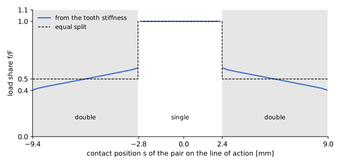
(a) The share of the tooth force a pair carries, from the tooth stiffness against the equal split.
(b) The mesh stiffness, per millimetre of face width.
Figure 14.3.4: The load variation of the spur gears of Figure 14.3.1 from the stiffness of the teeth, and the mesh stiffness over one passage of a pair through the mesh.
At the pitch point the gear model reproduces the cylinder: a half-width of 0.111 mm, a Hertz pressure of 765 MPa, and the largest von Mises stress, 440 MPa or 0.575 of the pressure, 0.69 half-widths below the flank, within 3 % of the theory with elements a ninth of the half-width.
The load sharing of Figure 14.3.4 differs from the equal split. A pair that enters takes only 40 % of the force, because its contact is at the wheel’s tip and the pinion’s root, where the wheel’s tooth is most flexible, and its share grows to 60 % as the contact moves towards the pitch point. The load variation of a spur pair is therefore not a staircase but a ramp with two steps, and the root stress in double contact is up to 19 % lower than with the equal split. The largest root stress, in single contact, does not change, so the factor of 1.5 over Lewis stands.
The mesh stiffness jumps between about 10 and 14 N/(mm·µm) each time a pair enters or leaves. The gears deflect a little more and a little less at the tooth frequency, and that periodic deflection excites the whine of spur gears.
Further reading
The models are written in Gridap [1,2]. The Hertz solution for two cylinders and the depth of the largest shear stress are in Budynas and Nisbett [3].
References
[1]
Badia S, Verdugo F. Gridap: An extensible finite element toolbox in Julia. Journal of Open Source Software 2020;5:2520. https://doi.org/10.21105/joss.02520.
[2]
Verdugo F, Badia S. The software design of Gridap: A finite element package based on the JuliaJIT compiler. Computer Physics Communications 2022;276:108341. https://doi.org/10.1016/j.cpc.2022.108341.