9.3 Modelling spur gears in SolidWorks
A printed, laser-cut or CNC-milled gear has no generating cutter. The machine follows the outline of the CAD model, so the model has to carry the true involute of the spur gear chapter, and a flank approximated by arcs is printed exactly as wrong as it was drawn.
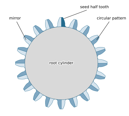
We build a SolidWorks part from the module \(m\), the tooth count \(N\) and the pressure angle \(\varphi\) alone. A model whose features refer to faces of the solid fails when \(N\) changes from 20 to 50, with Could not find face or plane. Ours has one equation driven curve for the flank and a sketch that holds the same entities for every \(N\), so it rebuilds. The part needs global variables, two sketches, two extrusions, a fillet, a circular pattern and a mirror (Figure 9.3.1).
Code
N, m = 20, 1
r_p, r_b, r_a, r_f = gear_radii(N, m)
gear = Polygon(gear_profile_points(N, m)[:, :2]).buffer(0)
teeth = gear.difference(Point(0, 0).buffer(r_f, 256))    # everything outside the root cylinder
pitch = 2*np.pi/N                                         # angular pitch; tooth k is centred at 90° + k pitch


def wedge(a0, a1, R=2*r_a):
    """A sector from the centre between the polar angles a0 and a1."""
    a = np.linspace(a0, a1, 60)
    return Polygon(np.vstack([[0, 0], R*np.column_stack([np.cos(a), np.sin(a)])]))


fig, ax = plt.subplots(figsize=(5.5, 5.5))
ax.fill(*Point(0, 0).buffer(r_f, 256).exterior.xy, color='0.85', ec='0.5', lw=0.8)
for k in range(N):
    c = np.pi/2 + k*pitch
    right = teeth.intersection(wedge(c - pitch/2, c))     # the half that is sketched and patterned
    left = teeth.intersection(wedge(c, c + pitch/2))      # the half the mirror adds
    for g, col in ((right, '#236b8e' if k == 0 else '#7fa7c2'), (left, '#d6e4ee')):
        for poly in getattr(g, 'geoms', [g]):
            if poly.geom_type == 'Polygon':
                ax.fill(*poly.exterior.xy, color=col, ec='#236b8e', lw=0.6)
ax.annotate('seed half tooth', xy=(0.35, r_a - 0.4), xytext=(4.5, r_a + 2.2),
            arrowprops=dict(arrowstyle='-', color='k', lw=0.8), path_effects=halo)
ax.annotate('circular pattern', xy=(r_p*np.cos(np.pi/2 - 3*pitch - 0.05),
                                    r_p*np.sin(np.pi/2 - 3*pitch - 0.05)),
            xytext=(8.5, 10.5), arrowprops=dict(arrowstyle='-', color='k', lw=0.8),
            path_effects=halo)
ax.annotate('mirror', xy=(r_p*np.cos(np.pi/2 + 3*pitch + 0.05),
                          r_p*np.sin(np.pi/2 + 3*pitch + 0.05)),
            xytext=(-12.5, 10.5), arrowprops=dict(arrowstyle='-', color='k', lw=0.8),
            path_effects=halo)
ax.text(0, 0, 'root cylinder', ha='center', va='center', path_effects=halo)
ax.set_xlim(-r_a - 3, r_a + 3)
ax.set_ylim(-r_a - 1, r_a + 3.5)
ax.set_aspect('equal')
ax.axis('off')
plt.show()Building the gear
Global variables
Open Tools, Equations and enter the global variables of Table 9.3.1. Everything downstream refers to them by name, so no dimension is typed as a number.
| Variable | Expression | Meaning |
|---|---|---|
N |
20 |
Number of teeth |
m |
1 |
Module (mm) |
PressureAngle |
20 |
Pressure angle (degrees) |
FaceWidth |
10 |
Gear thickness (mm) |
PitchRadius |
"m" * "N" / 2 |
Pitch circle radius |
BR |
"PitchRadius" * cos("PressureAngle") |
Base circle radius |
TipRadius |
"m" * ("N" + 2) / 2 |
Tip circle radius |
RootRadius |
"PitchRadius" - 1.25 * "m" |
Root circle radius |
t_tip |
sqr(("TipRadius" / "BR") ^ 2 - 1) |
Involute parameter at the tip |
MidAngle |
360 / ("N" * 4) |
Quarter of the angular pitch (degrees) |
MirrorAngle |
90 / "N" + (tan("PressureAngle") - "PressureAngle" * pi / 180) * 180 / pi |
Cusp line to tooth centreline (degrees) |
R_fillet |
0.9 * "BR" * (pi / (2 * "N") - (tan("PressureAngle") - "PressureAngle" * pi / 180)) |
Root fillet radius |
The parameter t_tip is the value of \(\alpha\) at which the involute reaches the tip circle, from \(r = r_b\sqrt{1+\alpha^2}\). MirrorAngle is 9.3.2 and R_fillet is the root fillet radius. In R_fillet the involute function of 9.2.9 is written out inline and not stored as its own variable: SolidWorks assigns angular units to a global that looks like an angle, and the result is then unusable in a length expression. Multiplying by BR inside one expression keeps R_fillet in millimetres.
The tooth flank as a single equation driven curve
Open a sketch on the Top Plane. From Tools, Sketch Entities, choose Equation Driven Curve and fill in the dialog as in Table 9.3.2.
| Field | Entry |
|---|---|
| Type | Parametric |
| \(x_t\) | the first expression below |
| \(y_t\) | the second expression below |
| \(t_1\) | -1 |
| \(t_2\) | 1 |
x_t: "BR" * (sin(((t * "t_tip") + sqr((t * "t_tip") ^ 2)) / 2) - ((t * "t_tip") + sqr((t * "t_tip") ^ 2)) / 2 * cos(((t * "t_tip") + sqr((t * "t_tip") ^ 2)) / 2))y_t: "BR" * (cos(((t * "t_tip") + sqr((t * "t_tip") ^ 2)) / 2) + ((t * "t_tip") + sqr((t * "t_tip") ^ 2)) / 2 * sin(((t * "t_tip") + sqr((t * "t_tip") ^ 2)) / 2)) + ((t * "t_tip") - sqr((t * "t_tip") ^ 2)) / 2 * "BR"The expressions are long only because SolidWorks offers no way to name an intermediate result, so the same subexpression is repeated. Writing \(v = t\,t_\text{tip}\) and abbreviating \(v^{+} = \max(v,0)\) and \(v^{-} = \min(v,0)\), the pair is
\[ x(t) = r_b\left[\sin v^{+} - v^{+}\cos v^{+}\right], \qquad y(t) = r_b\left[\cos v^{+} + v^{+}\sin v^{+}\right] + r_b\,v^{-} \tag{9.3.1}\]
For \(t > 0\) we have \(v^{-} = 0\) and this is the involute, 9.2.1, evaluated at \(v\). For \(t < 0\) we have \(v^{+} = 0\), the involute terms freeze at the cusp \((0, r_b)\), and the remaining term slides the point straight down the \(y\) axis. One entity therefore carries the involute above the base circle and the radial line below it, and the sketch never gains or loses an entity as \(N\) crosses the \(41.5\) teeth of 9.2.7, where the root circle passes the base circle. The maximum and minimum are written algebraically because the dialog accepts no conditional (Replacing a conditional with algebra). Figure 9.3.2 shows the curve on either side of the crossover.
Code
fig, axes = plt.subplots(2, 1, figsize=(6, 8))
for ax, N_val in zip(axes, (20, 50)):
    r_p, r_b, r_a, r_f = gear_radii(N_val, 1)
    t_tip = np.sqrt((r_a/r_b)**2 - 1)
    t = np.linspace(-1, 1, 2001)
    x, y = unified_curve(t, r_b, t_tip)
    ax.plot(x[t >= 0], y[t >= 0], color='#236b8e', lw=2)     # v > 0: the involute
    ax.plot(x[t <= 0], y[t <= 0], color='0.55', lw=2)        # v < 0: the radial line
    ax.plot(0, r_b, 'o', color='#236b8e', ms=4)              # the cusp joins the two
    for r, name in ((r_a, '$r_a$'), (r_p, '$r_p$'), (r_b, '$r_b$'), (r_f, '$r_f$')):
        col = '#c07a2c' if name == '$r_b$' else '0.35'
        a = np.linspace(-1.4/r, 1.4/r, 100)                  # arcs 2.8 mm long
        ax.plot(r*np.sin(a), r*np.cos(a), '--' if name == '$r_p$' else '-', color=col, lw=1)
        side = -1 if name == '$r_b$' else 1                  # base label left, the rest right
        ax.text(side*1.5, r*np.cos(a[-1]), name, color=col, va='center',
                ha='right' if side < 0 else 'left', path_effects=halo)
    where = 'inside' if r_f < r_b else 'outside'
    ax.set_title(f'$N = {N_val}$: root circle {where} the base circle', fontsize=11)
    ax.set_xlim(-2.2, 2.2)
    ax.set_ylim(r_f - 1.0, r_a + 0.3)
    ax.set_aspect('equal')
    ax.set_xlabel('$x$ (mm)')
    ax.set_ylabel('$y$ (mm)')
plt.tight_layout()
plt.show()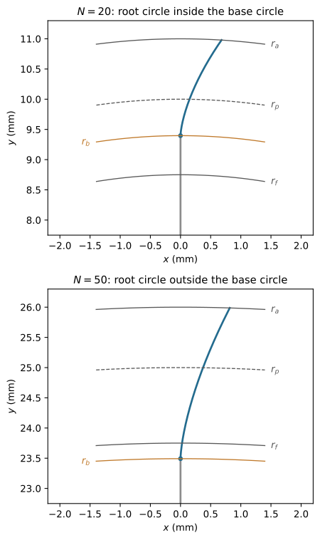
Sketching the half tooth
Stay in the same sketch.
- Add construction circles centred on the origin at
RootRadius,BR,PitchRadiusandTipRadius. They give the flank something to be dimensioned against and supply the intersection points of the next step. - Draw a construction line from the origin to the point where the flank crosses the pitch circle, with a coincident relation between its endpoint and that intersection, so that the line follows the curve when \(N\) changes. This line is the datum of the tooth, and it must run to the pitch circle: the point where the involute leaves the base circle carries no information about tooth thickness (Why the datum must be the pitch circle). In Figure 9.2.9 this line is \(OP\) with \(P\) on the pitch circle, the line to the cusp is \(OC\), and the angle between them is \(\psi = \operatorname{inv}\varphi\); Figure 9.2.10 draws this step.
- Draw a second construction line from the origin at
MidAnglefrom the first. Tooth and space are equally wide at the pitch circle, so a quarter of the angular pitch takes us from the flank to the middle of the tooth: this line is the tooth centreline. - Close the profile with a centrepoint arc at
RootRadiusfrom the flank to the centreline, a line along the centreline from that arc out to the tip, and a centrepoint arc atTipRadiusback to the flank. Leave the root corner sharp; the fillet comes later as a feature.
Figure 9.3.3 shows the finished sketch.
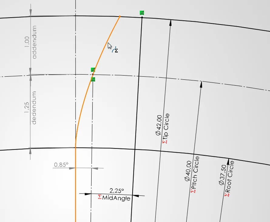
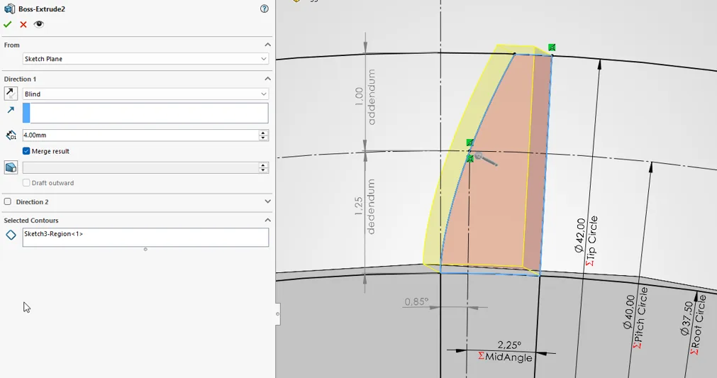
MidAngle \(= 2.25°\) from there to the tooth centreline.
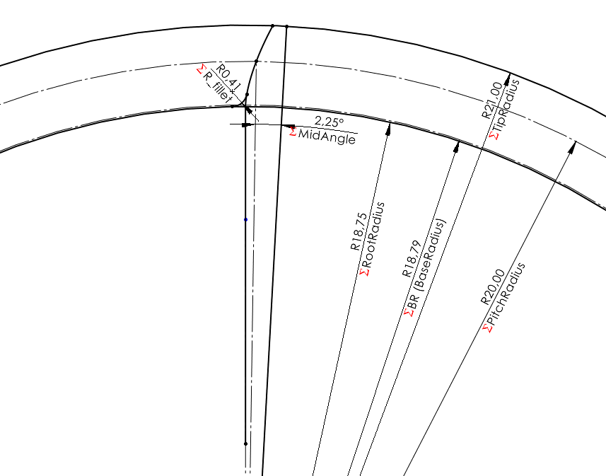
RootRadius \(= 18.75\), BR \(= 18.79\), PitchRadius \(= 20.00\) and TipRadius \(= 21.00\). At \(N = 40\) the root circle lies just inside the base circle. This version also rounds the root corner in the sketch with R_fillet \(= 0.41\); the procedure above adds the fillet as a feature instead (Figure 9.3.5).
Selecting contours instead of trimming
The flank deliberately overshoots, reaching down to \(r_b(1 - t_\text{tip})\), which is \(3.68\) mm at \(N = 20\) against a root radius of \(8.75\) mm. It has to overshoot, because \(t_1\) is set once and must place the start of the curve below the root circle for every tooth count we care about.
We do not trim the overshoot away, because we cannot. SolidWorks refuses to shorten an equation driven curve, and Mirror Entities likewise either refuses or converts the curve to an ordinary spline and severs its link to the global variables. Attempting either is how this construction is usually broken.
Instead we let the overshoot stand and choose contours. Where the overshoot crosses the root arc it divides the sketch into several closed regions, and the extrusion takes only the one we want. Use Selected Contours and pick the half tooth. The regions the overshoot cuts off below the root arc stay unselected, and their number may change with \(N\) without affecting anything. Figure 9.3.4 shows the single entry this leaves in the Selected Contours field.
Extruding, patterning and mirroring
Build the solid in the order of Table 9.3.3. Every reference is a datum plane, a datum axis or a global variable, never a face or an edge of the model.
| Step | Feature | Settings |
|---|---|---|
| 1 | Extruded Boss, root cylinder | circle of radius RootRadius on the Top Plane; Blind, "FaceWidth" |
| 2 | Extruded Boss, half tooth | the half tooth sketch; Blind, "FaceWidth"; Merge result on; Selected Contours: the half tooth (Figure 9.3.4) |
| 3 | Fillet | the root edge of the flank; radius "R_fillet"; Tangent propagation on (Figure 9.3.5) |
| 4 | Axis | Insert, Reference Geometry, Axis: Front Plane and Right Plane |
| 5 | Circular Pattern | features: steps 2 and 3; axis of step 4; \(360°\), equal spacing; Geometry pattern off (Figure 9.3.6) |
| 6 | Plane | Insert, Reference Geometry, Plane: Right Plane at angle "MirrorAngle", and the axis of step 4 |
| 7 | Mirror | plane of step 6; features: steps 2, 3 and 5 (Figure 9.3.7) |
After step 5, tie the number of instances to the tooth count by adding
"D1@CirPattern1" = "N"to the equations.
WarningWhy this order
A circular pattern re-creates each instance from the feature definition and does not copy solid geometry, so every reference of the seed must still resolve after the rotation. A face or an edge is a topological index that renumbers when a large change of \(N\) regenerates the solid, and the feature then fails with Could not find face or plane. The sketches therefore sit on the Top Plane, the extrusions are Blind and not Up To, and the axis and the mirror plane are built from datums.
The fillet comes before the pattern, so that one edge is blended and copied \(N\) times instead of \(2N\) edges selected afterwards. As a feature it also solves the tangency itself, which matters because above about \(N = 25\) the tangency point lies on the involute (The root fillet radius).
The mirror comes last. A mirror carries its plane as a reference, and patterning a mirror makes SolidWorks re-solve that reference at every rotated position; Geometry pattern would skip the re-solve, but SolidWorks declines to apply it to a mirror seed. The pattern holds only the copies, not the seed, so the half tooth and its fillet go into the mirror beside the pattern, or the seed tooth keeps half its profile. The root cylinder stays out of the mirror, since it is symmetric about every plane through the axis.
Mirroring the whole array is exact. A reflection turns a rotation into its inverse, so the mirror of half tooth \(k\) lands on the missing half of tooth \(-k\), and \(k\) runs over all \(N\).
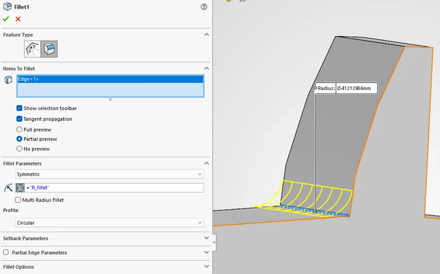
= "R_fillet" and not a number, so the fillet tracks the tooth count, and Tangent propagation carries the blend along the root edge. SolidWorks solves the tangency, so the same construction works once that point moves from the radial segment onto the involute.
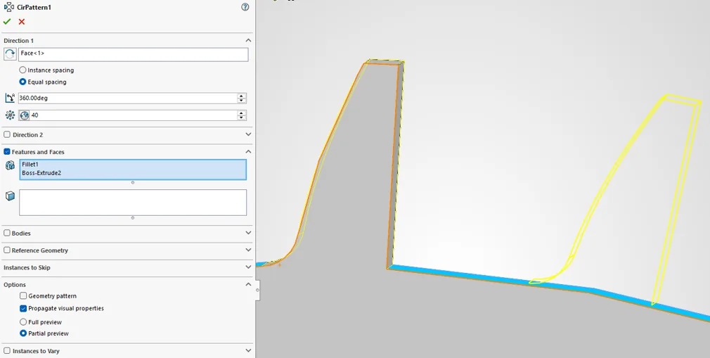
Fillet1 and Boss-Extrude2 in the features box and the faces box left empty. Direction 1 here holds Face<1>. A cylindrical face does supply a valid axis, but it is a topological reference, and the datum axis of step 4 is what survives a large change in \(N\).
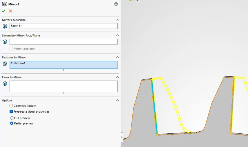
CirPattern1; the seed features have to go in alongside it, or the tooth the pattern grew from keeps only half its profile. The Mirror Face/Plane field here holds Face<1>, the reference that fails on a large change of \(N\); it should be the datum plane of step 6.
Checking the model
- Set
Nto 12 and rebuild, then set it to 50 and rebuild again. The two straddle the crossover of 9.2.7, so a model that survives both has used the radial part of the flank and done without it. - Measure the tooth thickness along the pitch circle. At \(m = 1\) it must be \(\pi m/2 = 1.5708\) mm for every \(N\). A tooth that looks right but measures \(1.273\) mm at \(N = 20\) has its datum on the base circle (Why the datum must be the pitch circle).
Robustness and its limits
The sketch contains the same entities for every \(N\): one equation driven curve, two arcs and one line. The curve runs from below the root to the tip, the root edge the fillet blends always exists, and the parameter bounds stay at \(t \in [-1, 1]\). Nothing in the sketch depends on whether \(r_f\) is larger or smaller than \(r_b\), the switch that usually breaks a parametric gear model. The part has rebuilt from \(N = 8\) to \(N = 100\). Below 18 teeth it differs from the gear a hob would cut, and above about 42 its fillet is thinner than a \(0.4\) mm extrusion (Limits of the model).
Derivations
None of this is needed to build the gear; it shows why the expressions of the procedure are right.
Why the datum must be the pitch circle
The tooth thickness at radius \(r\) is 9.2.10. Setting \(r = r_b\) makes \(\varphi_b = 0\), so \(\operatorname{inv}\varphi_b = 0\) and the bracket loses the term that distinguishes one radius from another: the base circle carries no thickness information.
This is why the datum line of the sketch runs to the pitch circle. Taking it to the point where the involute leaves the base circle, \(OC\) in place of \(OP\) in Figure 9.2.9, is tempting, since the curve visibly starts there and the point is easy to snap to, but it drops \(\operatorname{inv}\varphi\) from the half tooth angle. Every tooth then comes out \(2\operatorname{inv}\varphi = 1.71°\) too thin. At \(N = 20\) and \(m = 1\) the pitch circle thickness is \(1.273\) mm against \(1.571\) mm, 19 % short: invisible by eye, and in mesh it shows as \(0.3\) mm of play at every tooth. Mick of Kusel Design, Australia, found this error in an earlier version of this construction.
The angle from the cusp line to the tooth centreline is the half tooth angle at the pitch circle plus \(\operatorname{inv}\varphi\),
\[ \psi_c = \frac{\pi}{2N} + \operatorname{inv}\varphi \tag{9.3.2}\]
the global variable MirrorAngle, which evaluates to \(5.354°\) at \(N = 20\). It places the mirror plane, and it can also replace the datum line in the sketch: dimension the centreline from the cusp line by MirrorAngle. Both give the same tooth. The datum line makes the geometry visible in the sketch, the angle saves an entity.
Replacing a conditional with algebra
For any real \(v\), \(\sqrt{v^2} = |v|\), and therefore
\[ \max(v, 0) = \frac{v + \sqrt{v^2}}{2}, \qquad \min(v, 0) = \frac{v - \sqrt{v^2}}{2} \tag{9.3.3}\]
Each expression returns \(v\) when \(v\) has the matching sign and zero otherwise, using nothing but arithmetic and a square root. In SolidWorks syntax they read (v + sqr(v ^ 2)) / 2 and (v - sqr(v ^ 2)) / 2, the subexpression repeated throughout the flank curve.
The equation driven curve dialog provides arithmetic, powers and the elementary functions, and no conditional of any kind. Without 9.3.3 the flank would be two entities, a line below the base circle and an involute above it, and the line would have to disappear when \(r_f > r_b\). The sketch topology would then depend on \(N\), and at the crossover of 9.2.7 every relation and fillet attached to the vanishing line would break. Written algebraically, the branch leaves the topology fixed.
The root fillet radius
A hobbed gear gets its root fillet from the tip radius of the generating rack, which ISO 53 sets at \(\rho_{fP} = 0.38\,m\) for the standard basic rack tooth profile, its informative annex offering \(0.30\,m\), \(0.25\,m\) and \(0.39\,m\) as alternatives for lighter loading and for full root radius work [1]. Reproducing that fillet means simulating the cutter, as the rack does, and the model uses a simpler fillet built on the same principle.
According to ISO 53 [1], the largest fillet that the bottom clearance \(c_P\) of a \(20°\) rack admits, for \(c_P < 0.295\,m\), is
\[ \rho_{fP\max} = \frac{c_P}{1 - \sin\alpha_P} \]
and the standard clearance \(c_P = 0.25\,m\) returns \(0.3800\,m\): the tabulated \(0.38\,m\) is the largest fillet that fits, to two figures. We apply the same rule to the gear, taking the largest arc that fits the tooth space and backing away from it. Subtracting the tooth thickness of 9.2.10 from the circular pitch at the base circle leaves a space whose half width is
\[ \frac{e_b}{2} = r_b\left(\frac{\pi}{2N} - \operatorname{inv}\varphi\right) \tag{9.3.4}\]
and we take \(R_f = 0.9\,e_b/2\), the variable R_fillet of Table 9.3.1.
The fillet lies at the root, where the space is narrower than at the base circle. Two fillets from adjacent teeth clear one another when the arc each subtends on the root circle is smaller than the half space there,
\[ \arcsin\frac{R_f}{r_f + R_f} < \beta, \qquad \beta = \frac{\pi}{2N} - \operatorname{inv}\varphi \tag{9.3.5}\]
or \(R_f < r_f \sin\beta / (1 - \sin\beta)\). A fillet tangent to a radial flank touches it at the radius \(\sqrt{r_f^2 + 2 r_f R_f}\); where that exceeds \(r_b\) there is no radial flank to touch and the fillet meets the involute. Table 9.3.4 evaluates both at \(m = 1\) mm.
Code
phi = np.radians(20)
inv_phi = np.tan(phi) - phi                             # @eq-inv at the pitch circle
rows = []
for N in (8, 10, 20, 25, 26, 42, 60, 80, 100):
    r_p, r_b, r_a, r_f = gear_radii(N, 1.0)             # m = 1: lengths in mm
    beta = np.pi/(2*N) - inv_phi                        # half the tooth space, as an angle
    R_f = 0.9*r_b*beta                                  # R_fillet, 0.9 of @eq-space
    R_max = r_f*np.sin(beta)/(1 - np.sin(beta))         # largest fillet, @eq-clearance
    r_t = np.sqrt(r_f**2 + 2*r_f*R_f)                   # tangency on a radial flank
    rows.append((N, R_f, R_max, R_f/R_max, 'involute' if r_t > r_b else 'radial line'))
fillets = pd.DataFrame(rows, columns=['$N$', '$R_f$ (mm)', 'largest $R_f$ (mm)',
'ratio', 'fillet meets'])R_fillet against the largest fillet of 9.3.5, and the part of the flank it meets, at \(m = 1\) mm.
| \(N\) | \(R_f\) (mm) | largest \(R_f\) (mm) | ratio | fillet meets |
|---|---|---|---|---|
| 8 | 0.614 | 0.606 | 1.014 | radial line |
| 10 | 0.601 | 0.619 | 0.971 | radial line |
| 20 | 0.538 | 0.594 | 0.906 | radial line |
| 25 | 0.507 | 0.566 | 0.895 | radial line |
| 26 | 0.5 | 0.56 | 0.893 | involute |
| 42 | 0.4 | 0.454 | 0.879 | involute |
| 60 | 0.286 | 0.328 | 0.873 | involute |
| 80 | 0.16 | 0.184 | 0.869 | involute |
| 100 | 0.034 | 0.039 | 0.867 | involute |
The factor \(0.9\) leaves a margin of 9 % at \(N = 20\), but only 3 % at \(N = 10\), and at \(N = 8\) the two fillets in one space overlap. Made as a feature this is harmless: the two blends merge into one rounded root, what ISO 53 calls a full root radius profile. Made in the sketch it would have been an error. Above about \(N = 25\) the fillet meets the involute, and a feature on the root edge solves for that point where a sketch fillet would have to be told where it is; the procedure therefore fillets the solid.
At the other end the fillet vanishes. 9.3.4 shrinks with \(N\) and turns negative when \(\pi/(2N) = \operatorname{inv}\varphi\), at \(N = 105\). From about \(N = 42\) the fillet is thinner than a \(0.4\) mm extrusion width, so the feature still rebuilds but the printed part has no fillet.
Limits of the model
A rack cutter undercuts a gear of fewer than 18 teeth (Undercut). Our model has no cutter and draws the full involute regardless, so below 18 teeth it is a valid involute gear but not the gear a hob would cut. Example 2 shows that the two differ by little down to about 12 teeth.
The model assumes no profile shift. A shift \(x\) widens the tooth at the pitch circle by 9.2.13, which adds \(2x\tan\varphi/N\) (in radians) to MidAngle and to 9.3.2 and subtracts it inside the bracket of R_fillet, and it moves TipRadius and RootRadius out by \(xm\).
The model has no backlash and no tip relief. A pair of these gears meshes with zero theoretical clearance, so a real pair needs the teeth thinned slightly, and the profile runs sharp to the tip circle where a loaded gear would have the corner eased.
Problems
Problem 1: A 30-tooth gear. For a gear of \(N = 30\) teeth at \(m = 1\) mm and \(\varphi = 20°\), evaluate MirrorAngle and R_fillet, and decide whether the root fillet meets the radial line or the involute.
Answer: MirrorAngle \(= 90/30 + 0.854 = 3.854°\). With \(r_b = 14.095\) mm and \(\pi/60 - \operatorname{inv}20° = 0.03746\), R_fillet \(= 0.9 \cdot 14.095 \cdot 0.03746
= 0.475\) mm. The fillet would touch a radial flank at \(\sqrt{13.75^2 + 2 \cdot 13.75 \cdot 0.475} = 14.22\) mm, above \(r_b\), so it meets the involute.
Problem 2: The wrong datum on a small pinion. A student draws the datum line of a pinion with \(N = 12\) and \(m = 2\) mm to the cusp on the base circle. How thick is the tooth at the pitch circle, and by what fraction is it too thin?
Answer: The half tooth angle at the pitch circle becomes \(\pi/24 - \operatorname{inv}20° = 0.1309 - 0.0149 = 0.1160\) rad, so \(t_p = 2 \cdot 12 \cdot 0.1160 = 2.784\) mm against \(\pi m/2 = 3.142\) mm, 11 % thin. The relative error \(2N\operatorname{inv}\varphi/\pi\) grows with \(N\), so a large gear suffers more.
Further reading
ISO 53 [1] defines the basic rack, its clearance and the alternative fillet radii, and Buckingham [2] derives the tooth thickness at any radius and the effect of a profile shift on it.
References
[1]
ISO 53:1998 Cylindrical gears for general and heavy engineering – Standard basic rack tooth profile. Geneva, Switzerland: International Organization for Standardization; 1998.
[2]
Buckingham E. Analytical mechanics of gears. New York: Dover Publications; 1988.