P, n, K_s, tau_allow = 200.0, 10_000, 1.5, 18.0     # W, rpm, -, MPa (PETG)

T = P/(2*np.pi*n/60)*1e3                              # running torque, N mm
T_d = K_s*T                                           # design torque, N mm
d_min = (16*T_d/(np.pi*tau_allow))**(1/3) # mm9.17 Lab instruction – Shaft and coupling
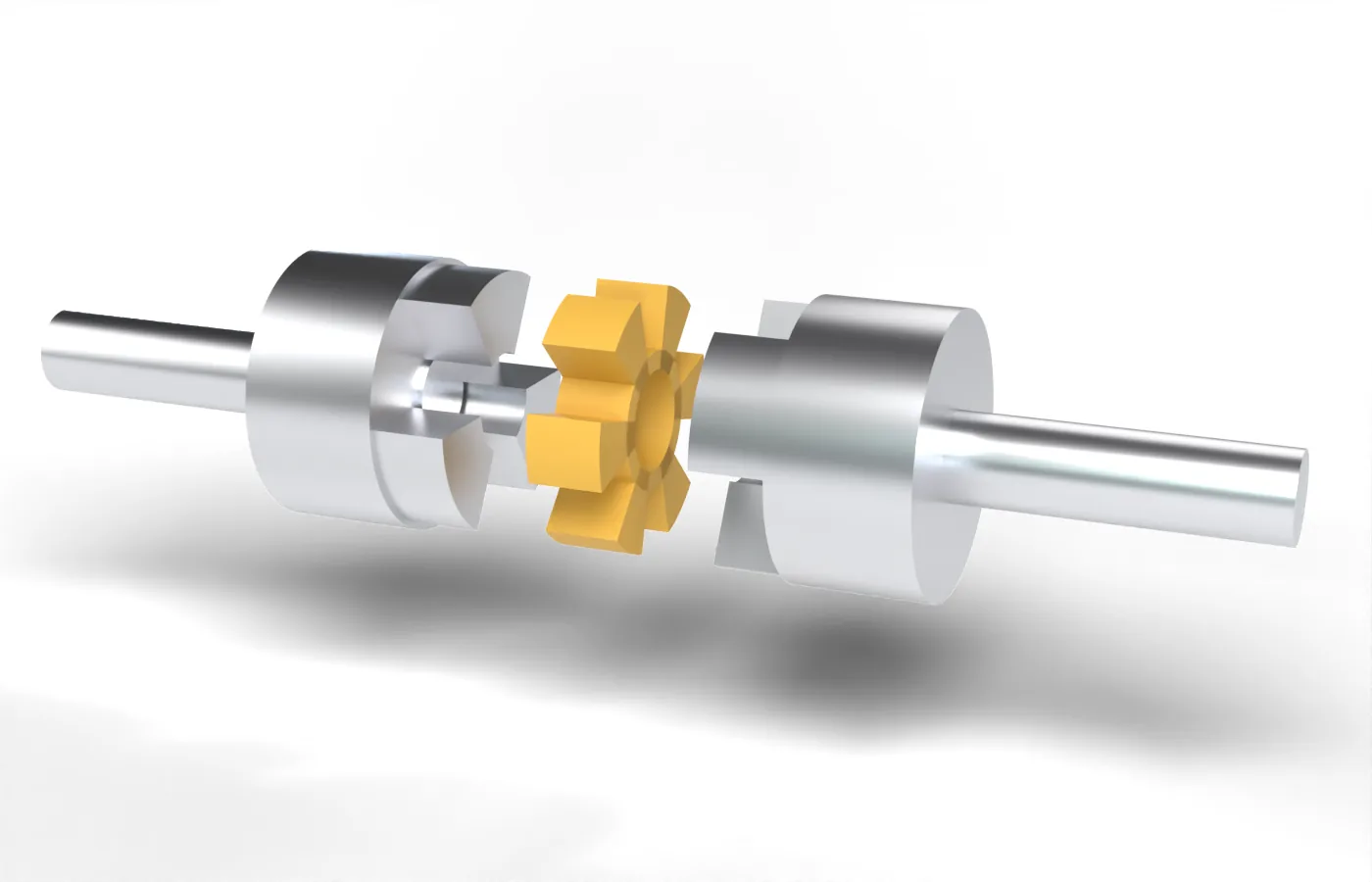
The motor of the RC car drives the gearbox through a short shaft and a shaft couplingsv. axelkoppling. On the track the printed chassis flexes under load and over bumps, and the motor and the driven shaft move out of line with each other. A coupling chosen badly breaks the shaft, destroys the motor bearings, or adds rotating mass that slows the car’s acceleration. In this lab we act as the development engineer of the car: we size the shaft for a material of our choice and write a program that picks the lightest coupling from a catalogue that meets every requirement.
The lab takes two hours. It is carried out in groups and reported on one A4 page.
What is given
The motor and the requirements on the driveline are
| Quantity | Symbol | Value | Comment |
|---|---|---|---|
| Motor power | \(P\) | 0.35 kW | fixed input for this analysis |
| Speed | \(n\) | 15 000 rpm | speed at maximum power |
| Service factor | \(K_s\) | 1.8 | for heavy shocks in the driveline |
| Angular misalignment required | \(\beta_\text{req}\) | 1.0° | chassis flex over bumps |
| Parallel offset required | \(e_\text{req}\) | 0.25 mm | chassis flex over bumps |
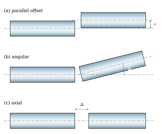
The two misalignments are those of Figure 9.17.2 (a) and (b). The coupling must allow both at once.
The shaft is made of one of five materials, each with an allowable shear stress:
| Material | \(\tau_\text{allow}\) [MPa] |
|---|---|
| PLA, standard printing plastic | 15 |
| PETG, a tougher printing plastic | 18 |
| PETG-CF, carbon-fibre reinforced PETG | 28 |
| PA-CF, carbon-fibre reinforced nylon | 35 |
| Shaft steel C45 | 90 |
The couplings come from a practice catalogue of five RC couplings:
| Type | Max torque [N·m] | Angle [°] | Offset [mm] | Max bore [mm] | Mass [g] | |
|---|---|---|---|---|---|---|
| A | rigid sleeve coupling | 1.2 | 0.0 | 0.00 | 4 | 4 |
| B | aluminium clamp coupling | 1.5 | 1.5 | 0.20 | 5 | 8 |
| C | jaw coupling, plastic | 1.0 | 2.0 | 0.40 | 6 | 5 |
| D | jaw coupling, aluminium | 2.5 | 1.5 | 0.35 | 6 | 12 |
| E | Oldham coupling, heavy duty | 4.0 | 1.0 | 1.00 | 8 | 22 |
Its couplings fit shafts of 4, 5, 6 and 8 mm only, so the computed diameter is rounded up to one of these.
Procedure
- Choose one of the five materials for the shaft.
- Compute the running torque \(T\) of the motor, the design torque \(T_d\) and the smallest shaft diameter \(d_\min\) for your material.
- Choose a standard diameter, 4, 5, 6 or 8 mm.
- Write a Python program that reads the catalogue and keeps the couplings that
- carry the design torque \(T_d\), (b) allow both misalignments, angle and offset, and
- fit your shaft, with a largest bore at least your diameter.
- Let the program print the lightest coupling that passes.
- Parameter study: let the program plot how \(T_d\) changes when the motor speed varies from 5000 to 25 000 rpm, and mark your own operating point at 15 000 rpm.
- Discussion: change the material in your program to the weakest (PLA) and then to the strongest (steel), and run it for both. How did the material change the size of the shaft and the coupling that was chosen in the end? What are the advantages and the drawbacks of a thick plastic shaft against a thin steel one in a racing car?
Analysis
The motor delivers the power \(P\) at the angular speed \(\omega = 2\pi n/60\), so its running torque is \(T = P/\omega\). A coupling and a shaft are sized for more than that: the service factorsv. servicefaktor \(K_s\) covers the shocks of the driveline, as for a coupling chosen from a catalogue in the couplings chapter,
\[ T = \frac{P}{\omega} = \frac{60\,P}{2\pi n}, \qquad T_d = K_s\,T \tag{9.17.1}\]
A solid round shaft in torsion has its largest shear stress at the surface, \(T/W\) with the torsional section modulus \(W = \pi d^3/16\) (8.13.5). Setting it equal to the allowable stress gives the smallest diameter,
\[ \tau_\max = \frac{16\,T_d}{\pi d^3} \le \tau_\text{allow} \quad\Rightarrow\quad d_\min = \left(\frac{16\,T_d}{\pi\,\tau_\text{allow}}\right)^{1/3} \tag{9.17.2}\]
The coupling is checked against the catalogue: its largest torque at least \(T_d\), its permitted angle and offset at least the required ones, and its largest bore at least the chosen diameter. The couplings chapter explains what each kind of misalignment does to a coupling that does not allow it.
We show the method with other numbers than those of the lab: a motor of 0.20 kW at 10 000 rpm, \(K_s = 1.5\) and a shaft of PETG.
The torques and the smallest diameter are
\[ \begin{aligned}T &=0.191~\text{N m},\quad T_d = K_s T =0.286~\text{N m}\\d_\min &= \left(\frac{16\,T_d}{\pi\,\tau_\text{allow}}\right)^{1/3} =4.33~\text{mm}\end{aligned} \]
so this shaft is made 5 mm thick. The catalogue goes into a table, one row per coupling, and a condition on a column keeps the rows that meet it. The torque requirement alone keeps every coupling:
catalogue = pd.DataFrame({
    "type": ["rigid sleeve", "aluminium clamp", "jaw, plastic", "jaw, aluminium", "Oldham"],
    "T_max": [1.2, 1.5, 1.0, 2.5, 4.0],           # N m
    "angle": [0.0, 1.5, 2.0, 1.5, 1.0],           # degrees
    "offset": [0.00, 0.20, 0.40, 0.35, 1.00],     # mm
    "bore": [4, 5, 6, 6, 8],                      # largest bore, mm
    "mass": [4, 8, 5, 12, 22]},                   # g
    index=list("ABCDE"))

catalogue[catalogue["T_max"] >= T_d/1e3]| type | T_max | angle | offset | bore | mass | |
|---|---|---|---|---|---|---|
| A | rigid sleeve | 1.2 | 0.0 | 0.00 | 4 | 4 |
| B | aluminium clamp | 1.5 | 1.5 | 0.20 | 5 | 8 |
| C | jaw, plastic | 1.0 | 2.0 | 0.40 | 6 | 5 |
| D | jaw, aluminium | 2.5 | 1.5 | 0.35 | 6 | 12 |
| E | Oldham | 4.0 | 1.0 | 1.00 | 8 | 22 |
Your program adds the conditions on the misalignment and the bore, joined with &, and picks the lightest of the couplings that remain, for instance with nsmallest(1, "mass"). For the parameter study, \(T_d\) from 9.17.1 falls as \(1/n\): the same power at a lower speed needs a larger torque, and so a thicker shaft.
How the coupling holds the shaft
The coupling’s hubs are shaft–hub joints, and on a thin plastic shaft they can be the weak point. The aluminium clamp coupling B grips the shaft by friction like the clamped hub, and 9.16.7 gives the clamping force it needs. A hub held by a set screw on a flat carries the torque as a pressure on the flat, and 9.16.23 of Locking a printed hub gives its largest value.
Report
Hand in on Canvas, as two files:
- your Python code, as a
.pyfile or a Jupyter notebook, and - a report of at most one A4 page as a PDF, with text, a table and a graph only.
The report holds
- a table of your computed values: \(T\), \(T_d\), the theoretical diameter and the chosen standard diameter,
- the name of the coupling your program chose, with a short reason,
- the graph of the speed study, and
- your answer to the discussion question, step 7 of the procedure.
Questions
Answer with the help of your program and the shaft–hub chapter.
- Which requirement removes the most couplings from the catalogue: the torque, the misalignment or the bore? Does that change with the material of the shaft?
- For PLA and for steel, how much more torque than \(T_d\) can your shaft carry at the standard diameter you chose? Which margin is larger, and why?
- In the speed study, at which speed would your chosen coupling no longer carry \(T_d\)?
If time permits
- Treat the clamp coupling B as a clamped hub with \(\mu = 0.15\). Which clamping force does 9.16.7 ask for to carry \(T_d\) on your shaft?
- A coupling hub held by a set screw on a flat 0.5 mm deep and 8 mm long: which pressure does 9.16.23 give on the flat of your shaft at \(T_d\)? Compare it with the allowable stress of your material.
Can you think of more questions? Discuss with your supervisor.