The bearings of a shaft remove five of its six freedoms and leave the rotation. A linear guide removes five and leaves a translation, and the count goes wrong in the same two ways: a freedom removed twice makes the carriage bind as soon as the parts are not where the drawing puts them, and a freedom not removed at all lets it rattle or tip and jam. The same count decides whether a 3D printer carriage runs or jams, whether a spacebar pressed at one end goes down or sticks, and whether a drawer pulled by one corner slides out or jams.
NoteExact constraint
Count the constraints before tightening the tolerances, hold small dimensions tight and let the large ones float, and add preload only once nothing is constrained twice.
A linear bearingsv. linjärlager guides a carriage along a straight line, and the questions are those of the rotating shaft: which freedoms are removed, by which bearing, and what happens when the parts are not exactly where the drawing puts them. The guides of Table 9.13.1 answer the last question in different ways. The rolling ones run lighter; the sliding ones damp vibrations better and survive chips and crashes.
Table 9.13.1: Linear guides, from the printer to the machine tool.
Guide
Contact
Play removed by
Where
rod and ball bushing (LM8UU)
balls rolling on a hardened rod
a tighter bushing, or a flexure and preload
3D printers (Example 1)
rod and polymer bushing
sliding, dry
a tighter bushing
quiet printers
V-wheels on an extrusion
ball-bearing wheels rolling in the extrusion’s grooves
cast iron scraped flat by hand, sliding on a film of oil
a tapered gib strip set with screws
manual lathes and mills
A polymer bushing is a plain bearing on a rod. The igus drylin RJ4JP-01-08 is made to the LM8UU’s dimensions, 8 mm bore, 15 mm outside and 24 mm long, so it drops into the same printed holder, and it slides dry on an iglidur polymer. It has no balls to rattle or to dent a soft rod and needs no grease, but its friction is about a hundred times that of the ball bushing, and the distance from the drive to the guide then decides whether the carriage slides or jams (9.13.1).
Example 1: A 3D printer carriage
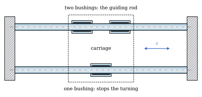
The print head of many 3D printers runs on two hardened 8 mm rods in LM8UU ball bushingssv. linjärkullager, 8 mm bore, 15 mm outside and 24 mm long, in which rows of balls roll on the rod and return through channels in the sleeve. Figure 9.13.1 shows the carriage from above with three bushings: two on the upper rod, one on the lower.
Figure 9.13.1: Example 1: the carriage of a 3D printer seen from above, on two 8 mm rods and three LM8UU ball bushings. The two bushings on the upper rod guide the carriage along it; the one on the lower rod stops it from turning about the upper rod.
Two bushings on one rod remove four freedoms: the two translations across the rod and the two tilts. The carriage can still slide along the rod and turn about it, and the single bushing on the second rod stops the turning. Three bushings do the job exactly. A fourth, on the lower rod, would also try to fix the distance between the rods, and two rods are never exactly parallel: over the travel the carriage would be forced to follow both, the bushings would bind at one end, and the motor would skip. Printers that use four bushings get away with it through the flexibility of the printed carriage and the rods, and a stiffer design lets the second rod’s bushing float sideways in a slot.
The rods must be hard. The balls of a bushing touch the rod at points, as in a ball bearing, and on a soft rod they roll grooves into it within hours; LM8UU rods are induction hardened and ground.
Where to pull
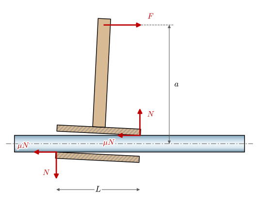
Three bushings fix where the carriage goes, but not how hard it is to push. The belt pulls the carriage at some distance \(a\) from the guiding rod, and that force has a moment about the bushings. Figure 9.13.2 treats the two bushings on the guiding rod as one sleeve of length \(L\), the distance between their outer ends, pushed along the rod by \(F\) at the offset \(a\). The sleeve tilts within its clearance until it bears on the rod at both ends, and the two normal forces \(N\) form the couple that balances the moment of \(F\):
\[
N L = F a
\]
Figure 9.13.2: Example 1: the bushings on the guiding rod drawn as one sleeve of length \(L\), pushed along the rod by \(F\) at the offset \(a\). The sleeve tilts in its clearance (exaggerated) and bears on the rod at its two ends with \(N\); friction \(\mu N\) acts at both against the motion.
Friction at the two contacts resists the motion with \(2\mu N\), so the sleeve moves only if \(F > 2\mu N = 2\mu F a/L\). The force cancels, and what remains is a condition on the geometry alone: the sleeve slides under any force if
\[
\frac{a}{L} < \frac{1}{2\mu}
\tag{9.13.1}\]
and jams under any force if the ratio is larger. Above the limit a stronger motor only presses the sleeve harder against the rod. The clearance does not appear in 9.13.1, so tighter tolerances do not cure jamming; they only make the sleeve tilt less before it locks. The cures are a shorter arm, a longer bearing, or less friction. Makers of plain linear bearings state the rule as a ratio of 2:1, which is 9.13.1 for \(\mu = 0.25\)[1].
A recirculating ball bushing runs at about \(\mu = 0.001\)[2], a polymer liner on a steel rod at 0.06 to 0.18 [3], and polymer bushings are a popular swap on printers because they are quiet. We take the X carriage of Figure 9.13.1, with the belt halfway between the rods, and the bed of a printer whose Z axis is driven by one lead screw at the bed’s edge, the bed guided by two rods with bushings 45 mm long and its far edge 200 mm away:
Code
mu = {'ball bushing': 0.001, 'polymer bushing': 0.18}geometry = {'X carriage': (25.0, 68.0), 'Z bed': (200.0, 45.0)} # (a, L) [mm]ratio = {k: a/L for k, (a, L) in geometry.items()}limit = {k: 1/(2*m) for k, m in mu.items()} # @eq-lb-jam
The X carriage is far inside both limits and runs on either bushing. The Z bed is far inside the limit of ball bushings and beyond that of polymer ones: converted to polymer bushings, it jams. The force on the bed is the lead screw’s, at the bed’s edge, but the weight of the bed and the print hangs on the far side too, and the moment of both is what the bushings must carry.
A second rule follows from the same statics. The friction of a carriage is the sum of the friction at its bushings, \(\mu\) times the normal load on each, and the resultant of those forces lies between the rods, nearer the one that carries more. A belt attached on that line pulls the carriage without any moment, and the guides carry no couple from the drive at all. Most printer carriages clamp the belt between the rods, close to it.
Rattle or bind
The LM8UU has clearance, a few hundredths of a millimetre between balls, sleeve and rod, and the print head moves by that much when the belt reverses. The way to remove play is a tighter bushing or a preload, and either brings back the over-constraint of the four bushings: the rods are not exactly parallel, the carriage is forced to follow both, and it binds. Free movement, no play and tolerance to the parts’ variation pull against each other (Example 2). The way out is to take the steps in order: first constrain the carriage exactly, then remove the play in the contacts that remain.
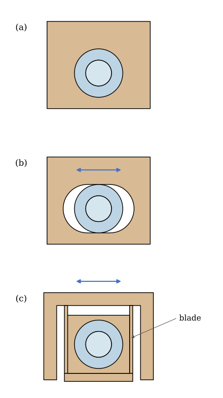
Figure 9.13.3: Example 1: three ways to hold the bushing on the second rod, seen along the rods. (a) Rigid in the carriage: with tight bushings, the carriage binds wherever the rods are not parallel. (b) In a slot: free across the rods, tight in the vertical direction. (c) On a printed parallel-blade flexure: free across the rods with no clearance at all.
Figure 9.13.3 shows the bushing on the second rod held three ways. Held rigidly (a), it fixes the distance between the rods at the carriage. In a slot (b), it is free across the rods and held vertically, so it stops the turning about the guiding rod and nothing else: it is the non-locating bearing of an arrangement, moved to a linear guide. A slot still has clearance in the vertical direction, however small.
The printed flexure (c) has none. Two thin blades carry the bushing holder; across the rods the holder moves by bending the blades, and vertically it is held by the blades in tension and compression, in which they are stiff. Each blade bends as a beam fixed at one end and guided at the other, with the stiffness \(12EI/l^3\). For blades of PETG 0.8 mm thick, 10 mm wide along the rod and 20 mm long, taking \(E \approx 2\) GPa for the printed material:
Code
E_petg, t_bl, w_bl, l_bl =2000.0, 0.8, 10.0, 20.0# [MPa], blade thickness, width, length [mm]I_bl = w_bl*t_bl**3/12k_flex =2*12*E_petg*I_bl/l_bl**3# two blades in parallel [N/mm]F_side = k_flex*0.2# rods 0.2 mm out of parallel [N]
The flexure is soft across the rods:
\[ \begin{aligned}k &=2.56~\text{N/mm},\quad F = k \cdot 0.2~\text{mm} =0.512~\text{N}\end{aligned} \]
Rods that are 0.2 mm out of parallel over the travel push the carriage sideways with half a newton, which the guiding rod’s bushings carry without noticing. The price of a flexure is that it is a spring: its force grows with deflection, so it suits small movements, and a printed blade creeps and fatigues. With the guide exactly constrained, the remaining play can then be removed by preload, a spring or an eccentric that presses the remaining contacts together, like the wave spring of the electric motor or the eccentric spacer of a V-wheel.
Example 2: The space bar of a keyboard
A keyboard’s space bar is the extreme case of Example 1. It is pressed anywhere along its length, and a stabilizer must make both ends go down together: a wire runs across under the bar and is held at each end in a plastic slider guided in a housing. The two stems are about 100 mm apart and guided over a few millimetres of travel, so a press at one end puts a ratio \(a/L\) of tens on the slider’s guide, far beyond the limit of 9.13.1 for plastic on plastic. Commercial stabilizers work because their parts are loose, and they rattle for the same reason. Enthusiasts take them apart and fill them with thick grease, which damps the noise but has to be applied by hand and seeps away.
Figure 9.13.4: Example 2: Ryan Norbauer on the stabilizer of his Seneca keyboard, from 8:41 (the failed experiments) through 20:18 (the pin joint design) [4].
Ryan Norbauer, who designs keyboards, set out to build a stabilizer that neither rattles nor needs grease (Figure 9.13.4). His first, precision-machined stems in tight polymer bushings, jammed as 9.13.1 predicts. Tighter fits bound, looser ones rattled, and the space bars of different makers differ in stem spacing by up to a millimetre, which every fit must accept. He summarises it as the choice of two out of free movement, good acoustics and tolerance to variation.
The consultants he brought in, the Danish firm RD8, found over-constraint: the standard slider runs on several widely spaced rails. Their demonstrator is the carriage of Example 1, built twice, once with every hole a close fit and once with one hole opened up so that three contacts remain; the first binds and the second runs. They replaced the rails with one short tongue and groove, held to a close clearance because the dimension is small and left free across the bar’s width, and only then added a small V-spring of spring steel that presses on the wire and stops the rattle. The final design is a linkage of ground pins with small preload beams where clearance remains.
Example 3: A ball screw axis
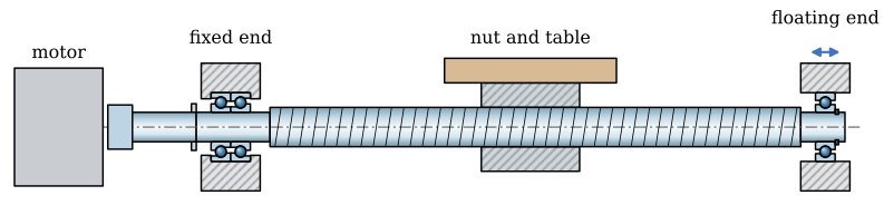
A CNC machine drives each axis with a ball screw, a screw whose nut runs on recirculating balls, and the screw is a shaft that needs bearings (Figure 9.13.5). The motor end is the fixed end: a pair of angular contact ball bearings back to back takes the axial force of the cut in both directions, preloaded so that the table does not move when the force reverses. The other end is the floating end: a deep groove ball bearing whose outer ring may slide in its housing. The friction in the nut heats the screw, the screw grows, and the floating end takes the growth. Hobby CNC machines buy the two ends as support units, sold as BK (fixed) and BF (floating).
Figure 9.13.5: Example 3: a ball screw axis. The fixed end at the motor holds the screw axially with two angular contact bearings back to back; at the floating end a deep groove ball bearing slides in its housing.
The table itself rides on profile rails, hardened rails with carriages in which balls or rollers recirculate. A carriage on a profile rail is preloaded, takes loads and moments in every direction, and is far stiffer than a bushing on a rod. A table on two rails has the over-constraint of the printer carriage, and the remedy is the same idea: one rail is mounted as the reference, pushed against a ground shoulder of the machine bed, and the second rail is aligned to the first through the table instead of to the bed.
Profile rail guides
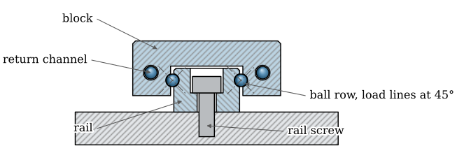
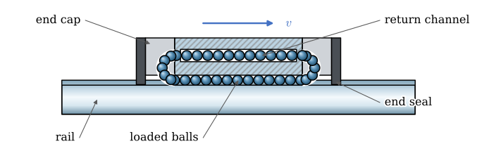
A profile rail guide is a ball bearing unrolled along a straight line. A hardened steel rail carries ground grooves along both sides, and a block runs on it on rows of balls (Figure 9.13.6). The balls cannot run out of the block’s length, so they recirculate (Figure 9.13.7): they carry the load on the straight between rail and block, turn round in a plastic end cap, run back through a channel in the block and turn again at the other end. Seals at both ends wipe dirt off the rail. The miniature MGN series that hobby printers and small CNC machines use has a 12 mm wide rail in size 12 and a block 27 mm wide and 35 mm long [5].
Figure 9.13.6: A miniature profile rail guide in MGN12 proportions, cut across the rail. Each of the two ball rows runs in Gothic-arch grooves and carries load along two load lines at 45°, so the block takes load in every direction across the rail. The returning balls run in channels in the block.
Figure 9.13.7: The block cut along one row of balls. The balls carry the load on the lower straight, turn round in the end caps and return through a channel in the block as it moves with \(v\); the end seals wipe the rail.
The grooves have a Gothic-arch profile, two arcs meeting in a point, so every ball touches the rail at two points and the block at two, and the load lines cross at 45°. Two rows with two load lines each carry load downwards, upwards and sideways, and because the rows lie apart, a single block also carries the three moments about its own axes: the roll about the rail and the pitch and yaw across it (Table 9.13.2). The longer MGN12H block nearly triples the pitch and yaw moments, because its ball rows are longer.
One block on one rail is therefore a complete guide, exactly constrained in the sense of Example 1: it removes five freedoms and leaves the travel along the rail. The dynamic rating of a linear guide is given for 50 km of travel, and the life follows from 9.11.2 with the revolutions replaced by distance: \(L = (C/P)^3 \cdot 50\) km.
The load capacity is rarely what decides. A print head of 0.4 kg accelerated at 10 m/s² with its centre of mass 40 mm from the rail puts a moment of 0.16 N·m on the block, about 1 % of the MGN12C’s rating. Profile rails are chosen for their stiffness and for having no play, and the block is sold in the preload classes of Table 9.13.3. Preload is the remedy of Rattle or bind built into the bearing: the balls are slightly oversized, so the block has no play to rattle in, and a Z0 MGN12C deflects by about 1 µm for every 44 N.
Table 9.13.3: Preload classes of the MGN12 and the flatness each asks of its mounting surface [5].
Class
Clearance or preload
Mounting surface flat to
ZF
4 to 10 µm clearance
0.05 mm over 200 mm
Z0
no clearance to a very light preload of 3 µm
0.05 mm over 200 mm
Z1
light preload, up to \(0.02\,C\)
0.025 mm over 200 mm
The price is accuracy of the mounting. A preloaded block on a rail is stiff because it cannot give, so it also cannot give when the rail is bolted to a surface that is not flat, and the error turns into force in the balls and friction in the travel. Two rails on one surface must also be parallel to within 9 µm [5]. Machine tools grind their reference surfaces to that. A printer frame of aluminium extrusions is not made to it, and the builders who succeed choose ZF or Z0 blocks, bolt one rail per axis and align it against a straight edge instead of trusting the extrusion.
A steel rail on an aluminium beam also forms a bimetal: aluminium expands by about \(23 \cdot 10^{-6}\) per kelvin and steel by \(12 \cdot 10^{-6}\), so a 300 mm rail on a beam that warms by 20 K is held to a beam that has grown 0.07 mm more than the rail. The screws carry the difference, and the beam bows slightly; the rail screws are spaced 25 mm apart along the rail, which keeps the shear on each small.
A block slid off the end of its rail drops its balls unless a retaining wire holds them in, and the original maker’s blocks have one but many cheap copies do not [5]. Blocks ship on a plastic dummy rail and move from it onto the steel rail end to end, without a gap.
Problems
Problem 1: Four bushings. A student builds a printer carriage on two rods with four LM8UU bushings in a stiff aluminium plate, and the carriage jams near one end of the travel. Why, and what are two fixes?
Answer:Four bushings fix the distance between the rods at both ends of the carriage, and the rods are not exactly parallel, so the carriage is forced against the rods where they diverge. Remove one bushing from the second rod, or let the second rod’s bushings float sideways in slotted holes, so that one rod guides and the other only stops the turning.
Problem 2: A cantilevered bed. The Z bed of Example 1 runs on polymer bushings with \(\mu = 0.18\), and its far edge is 200 mm from the guiding rods. How long must the bushing pair be, from outer end to outer end, for the bed not to jam? What else could change?
Answer:9.13.1 asks for \(L > 2\mu a = 2 \cdot 0.18 \cdot 200 = 72\) mm, with margin about 100 mm: two bushings spaced apart on each rod. Otherwise move the lead screw under the bed’s centre of mass, drive the bed from both sides, or go back to ball bushings.
Problem 3: The flexure’s blades. The flexure of Figure 9.13.3 (c) is printed with blades 1.2 mm thick instead of 0.8 mm. How large is the sideways force on the carriage now, for rods 0.2 mm out of parallel? Is it still acceptable?
Answer:The stiffness goes with \(t^3\): \((1.2/0.8)^3 = 3.4\) times stiffer, about 8.6 N/mm, and the sideways force is 1.7 N. Still small against the bushings’ capacity, but it adds friction at the guiding rod; thinner, longer blades keep it lower.
Further reading
Counting constraints, avoiding redundant ones and adding preload only afterwards are the subject of exact constraint design; Blanding [6] is the readable introduction, Slocum [7] the reference for precision machines, and Howell [8] for compliant mechanisms such as the flexure of Figure 9.13.3. The HIWIN catalogue [5] gives the ratings, preload classes and mounting tolerances of the miniature profile rails.