A spring gives back the work done on it, so a car on springs alone keeps bouncing after a bump. A dampersv. dämpare keeps the work. It turns it into heat in its oil, and the bouncing dies out. Its force comes from oil pressed through small passages, and the force a damper should not have comes from its seals. A damper that holds its oil and still feels sticky has more of the second than of the first. Figure 9.17.1 shows the damper of a car at work.
Figure 9.17.1: A monotube car damper at work. The piston pushes the oil (yellow) through its passages in both directions, and as the rod enters, the floating piston below compresses the gas; the colour of the gas shows its pressure, from cyan to magenta.
What a damper does
A damper mounted beside a spring resists the speed at which its two ends move together or apart. The simplest model of it is linear,
\[
F_d = c\,v
\tag{9.17.1}\]
where \(v\) is the relative speed of the two ends and \(c\) the damping coefficientsv. dämpkoefficient in N s/m: the force the damper gives per metre per second. The force always opposes the motion, so the damper takes the power
\[
\boxed{P = F_d\,v = c\,v^2}
\tag{9.17.2}\]
in compression and in extension alike, and turns it into heat. A damper with \(c = 35\) N s/m stroking at \(0.2\) m/s takes \(1.4\) W, which a small oil-filled body sheds without a noticeable rise in temperature.
A mass on a spring and a damper obeys \(m\ddot x + c\dot x + kx = 0\), the spring-damper system of Particle kinetics, Example 6. Its motion follows from two numbers, 7.2.4: the natural frequency \(\omega_n = \sqrt{k/m}\) and the damping ratio \(\zeta = c/(2\sqrt{km})\). A large \(c\) makes the mass creep back slowly, and a small \(c\) lets it bounce. Vehicle suspensions are tuned to a damping ratio somewhat below one, so that the body returns quickly and overshoots a little.
Anatomy of an oil damper
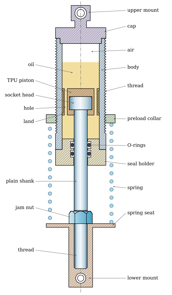
The damper of a car, of a motorcycle or of an RC car is a cylindersv. cylinder full of oil with a pistonsv. kolv on a rodsv. kolvstång[1]. Figure 9.17.2 shows a printed coilover cut along its axis, to scale. Its rod is an M5 socket screw. The head of the screw is held in a piston printed in TPU, the plain shank leaves the body through a sealsv. tätning, here two O-ringssv. O-ringar in a seal holder, and the thread at the end carries the rod end. When the rod moves, the piston pushes oil through the holes in it; the work done on the oil turns into heat, and the pressure on the piston resists the motion. Eyes at both ends, the mountssv. infästningar, carry the damper’s force into the car through pins, so the damper takes force only along its axis. The spring surrounds the body between a collar on the body’s outside thread and the seat on the rod end.
Figure 9.17.2: A printed coilover cut along its axis, to scale, each part in its own colour. The rod is an M5 socket screw: its head is held in a TPU piston with holes, its plain shank runs in two O-rings, and its thread carries the rod end. The cap and the upper mount are one part, and so are the rod end and the spring seat. Turning the collar on the body’s thread sets the preload.
The air under the cap makes room for the rod. Oil hardly compresses, so a body filled solid with it would lock as the rod enters; the displaced oil compresses the air instead, 9.17.18. Larger dampers keep oil and air apart with a rubber bladder, and car dampers use a gas-charged chamber [1].
The dampers of full-size cars add valves: thin spring-steel discs over the holes that open further as the pressure rises, so that the force can follow a curve chosen for compression and another for extension. A hobby damper relies on the holes alone, and so does every damper in this chapter.
Where the force comes from
The oil flows through the holes, and around the piston if it does not fit the bore, as a thin laminar stream. For laminar flow the volume per second through a passage is proportional to the pressure drop across it and inversely proportional to the viscosity \(\mu\) of the oil,
\[
Q = \frac{\kappa}{\mu}\,\Delta p
\tag{9.17.3}\]
and the constant \(\kappa\), in m\(^3\), depends only on the shape of the passage. For a hole of diameter \(d\) and length \(l\), the thickness of the piston, the flow in a pipe gives, according to [2],
A gap of height \(h\) between the piston and the bore is a flow between two close plates. Each strip of the gap of width \(\mathrm{d}s\) around the circumference passes \(h^3\,\mathrm{d}s\,\Delta p/(12\mu l)\)[2], so a gap that changes in height around the piston has
For a round piston of diameter \(D\) centred in its bore the gap is constant, \(\kappa_{\text{gap}} = \pi D h^3/(12l)\). A piston pushed off centre by \(e\) has \(h = h_0(1 + \varepsilon\cos\theta)\) with \(\varepsilon = e/h_0\), and the integral of \((1 + \varepsilon\cos\theta)^3\) around the bore gives the factor \(1 + \tfrac{3}{2}\varepsilon^2\): a piston that touches the bore on one side passes two and a half times the oil of a centred one.
Passages side by side add their \(\kappa\), since each carries its own share of the flow under the same pressure drop. A piston of area \(A_p\) moving at \(v\) pushes \(Q = A_p v\) through them all, and the pressure acts on the piston, \(F = \Delta p\,A_p\). Neglecting the area of the rod, the damper is linear, 9.17.1, with
For a piston with \(n\) equal holes and no gap this is
\[
c = \frac{128\,\mu\,l\,A_p^2}{\pi\,n\,d^4}
\tag{9.17.7}\]
The coefficient rises in proportion to the viscosity, falls with the fourth power of the hole diameter and with the cube of the gap. A hole \(10\,\%\) larger lowers \(c\) by a third, a gap \(10\,\%\) wider by a quarter. RC dampers are tuned with these numbers: shock oil is sold by its viscosity, and pistons by the number and the diameter of their holes.
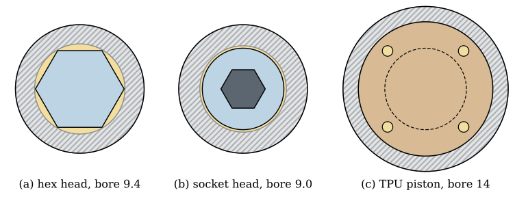
A drilled hole has the diameter of the drill to a hundredth of a millimetre. A gap is the difference between two diameters, and when one of them is printed, its scatter of a tenth of a millimetre or more is of the size of the gap itself. Figure 9.17.3 shows three pistons to one scale. The hex head of a bolt in a round bore leaves six crescents open past its flats, a socket head leaves a thin ring, and a TPU piston that touches the bore leaves the oil only its four holes.
Figure 9.17.3: Three pistons seen along the axis, oil in amber, to one scale. (a) An M5 hex head in a bore of 9.4 mm. (b) An M5 socket head of 8.5 mm in a bore of 9.0 mm. (c) A TPU piston touching a bore of 14 mm, the socket head inside it (dashed), with four holes of 1.1 mm.
The viscosity of oils is given as the kinematic viscosity \(\nu\), in centistokes (1 cSt = 1 mm\(^2\)/s), and the dynamic viscosity follows with the density, \(\mu = \rho\nu\). RC shock oil is silicone oil, sold in steps from about \(100\) to \(1000\) cSt or more. Dampers printed in a classroom are filled with baby oil instead, which does no harm on the skin or in the eyes when a seal lets go under pressure. Baby oil is light mineral oil thinned with isopropyl palmitate, and its bottle states no viscosity. The pharmacopoeia limits light mineral oil to at most about \(34\) cSt at \(40\,^\circ\)C [3], more at room temperature, while isopropyl palmitate has about \(9\) cSt at \(20\,^\circ\)C [4]. We take \(\nu = 24\) cSt and \(\rho = 840\) kg/m\(^3\), so \(\mu \approx 0.020\) Pa s, and treat the value as uncertain by a factor of two either way. A thin oil needs small passages, by 9.17.6, and an uncertain one needs a test, Example 4.
9.17.3 accounts for the friction of the oil along the passage. The oil also loses pressure where it enters and leaves a hole: it speeds up into the hole, and the jet that leaves it stirs itself to rest in the oil beyond. These losses grow with the square of the speed \(V\) of the oil in the hole, \(\Delta p = K\rho V^2/2\), with \(K \approx 0.5\) at a sharp-edged entrance and \(1\) at the exit [2]. In a short hole with laminar flow the loss is somewhat larger, so \(K = 1.5\) is a lower estimate. With \(n\) holes of total area \(a = n\pi d^2/4\) the oil moves at \(V = A_p v/a\), and the force on the piston gains a second term,
and below it the damper is nearly linear. The hole diameter has cancelled. It sets \(c\), while the viscosity, the length and the number of the holes set \(v_q\). A thick oil keeps a damper linear to high speeds. With baby oil, long holes and several of them keep \(v_q\) above the slow motions of the body, where friction competes with damping. Above \(v_q\) the force rises faster than \(v\), and the valves of car dampers shape that curve [1].
The damper in a suspension
The motion ratio
The spring and the damper are seldom at the wheel itself. On a wishbone suspension the coilover is mounted between the inner pivot and the wheel, so it moves less than the wheel. A shock that shortens by \(\delta x_s\) when the wheel rises by \(\delta z\) has the motion ratiosv. rörelseförhållande\(\mathrm{MR} = \delta x_s/\delta z\), which Suspension and steering geometry finds from the linkage. By virtual work, the force \(F_w\) at the wheel does the same work as the spring force at the shock, \(F_w\,\delta z = k x_s\,\delta x_s\), and with \(x_s = \mathrm{MR}\,z\) this gives \(F_w = k\,\mathrm{MR}^2 z\). The damper force transforms in the same way, so at the wheel the suspension has the wheel rate and the wheel damping
The ratio enters twice, once because the shock moves less than the wheel and once because its force acts on a shorter arm. A shock mounted halfway along the wishbone must be four times as stiff as a spring at the wheel.
Ride frequency and preload
The sprung mass \(m\) on one corner bounces on the wheel rate at the ride frequency\(\omega_n = \sqrt{k_w/m}\), and under its own weight it sinks by the static sag \(\delta_{st} = mg/k_w\). Each fixes the other,
so choosing the ride frequency chooses how far the car sinks on its springs, whatever its mass. According to [5], passenger cars have ride frequencies of about \(1\) to \(1.5\) Hz, a sag of \(25\) to \(11\) cm. A 1:10 model that sinks a tenth as far needs a ride frequency \(\sqrt{10} \approx 3.2\) times higher, by 9.17.11.
The threaded collar on the body of a coilover compresses the spring before the car stands on it. It sets the preload, and as in Springs, Example 5, Figure 9.16.19, the preload moves the working point along the characteristic without changing its slope. The rate, the ride frequency and the static compression of the spring stay the same. What changes is how much of that compression is already there when the shock is fully extended, and so how far the car sinks when it is set down: the collar sets the ride height.
Example 1: The shock absorbers of an RC car
A 1:10 RC car has an oil-filled coilover at each wheel. We size the spring and the damping of one corner and set the collar. The inputs of Table 9.17.1 are assumed, typical of a 1:10 car. The spring, sized with the formulas of Springs, is of hard-drawn wire, \(G = 79.3\) GPa, with closed and ground ends, and it should be solid safe.
Table 9.17.1: Example 1. Inputs for one corner of the car.
The wheel rate follows from the ride frequency, \(k_w = m\omega_n^2\), and the spring rate from 9.17.10, \(k = k_w/\mathrm{MR}^2\); 9.16.9 then gives the active coils. The damping follows from the damping ratio, \(c_w = 2\zeta\sqrt{k_w m}\) and \(c = c_w/\mathrm{MR}^2\), and 9.17.7 gives the holes. The collar is set last, from the static force on the spring, \(mg/\mathrm{MR}\).
Code
m_c, MR, f_n, zeta =0.5, 0.6, 4.0, 0.5# kg, -, Hz, - (assumed and chosen inputs)d_w, D_w, H_w, s_w =1.0, 12.0, 35.0, 15.0# wire, coil diameter, free height, stroke, mmG_w =79.3e3# MPaw_n =2*np.pi*f_nk_w = m_c*w_n**2/1000# wheel rate, N/mmk_req = k_w/MR**2# @eq-wheel-rate: the shock moves less, so it is stiffern_req = G_w*d_w**4/(8*D_w**3*k_req) # @eq-spring-rate-helical solved for nsag_wheel =9.81/w_n**2*1000# @eq-ride-sag, mm
The wheel rate, the spring rate the shock needs, the number of active coils that gives it, and the static sag at the wheel are
\[ \begin{aligned}k_w &=0.316~\text{N/mm},\quad k = \frac{k_w}{\mathrm{MR}^2} =0.877~\text{N/mm}\\ n &=6.54,\quad \delta_{st} = \frac{g}{\omega_n^2} =15.5~\text{mm}\end{aligned} \]
We wind \(n = 6.5\) active coils, which gives a rate a little above the target. With closed ends the spring has \(n + 2 = 8.5\) coils and a solid length of \(8.5\) mm. On the car it carries the static force \(mg/\mathrm{MR}\), and pressed solid it carries \(k(H_0 - L_s)\), with the stress of 9.16.12 against the strength of 9.16.15:
Code
n_w =6.5k_s = G_w*d_w**4/(8*D_w**3*n_w) # @eq-spring-rate-helical, N/mmC_w = D_w/d_wK_Bw = (4*C_w +2)/(4*C_w -3) # @eq-spring-wahlF_st = m_c*9.81/MR # static force on the spring, Nx_st = F_st/k_s # static compression of the spring, mmL_sw = (n_w +2)*d_w # solid length, closed endstau_solid = K_Bw*8*k_s*(H_w - L_sw)*D_w/(np.pi*d_w**3) # @eq-spring-stressS_sy_w =0.45*1783/d_w**0.190# @eq-spring-wire-strength
The spring is solid safe, by a small margin, and it will never be pressed solid on the car: the shock bottoms out first, as we see below. The ratio \(H_0/D = 2.9\) is above the pivoted-end limit of 9.16.14, but the spring is guided by the body of the damper it surrounds.
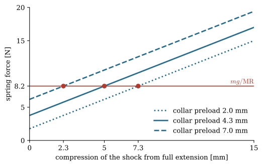
The collar decides where in the stroke the static compression of \(9.3\) mm falls, Figure 9.17.4. We set it so that the car sinks by \(5\) mm of the \(15\) mm stroke and the wheel can still drop into a hollow, which leaves a preload of \(9.3 - 5 = 4.3\) mm at full extension. Fully compressed, the spring is then shortened by \(4.3 + 15 = 19.3\) mm, short of the \(H_0 - L_s = 26.5\) mm that would close it.
Code
x = np.linspace(0, s_w, 50) # compression of the shock from full extension, mmfig, ax = plt.subplots(figsize=(6, 3.6))for x0, ls in ((2.0, ':'), (x_st -5, '-'), (7.0, '--')): ax.plot(x, k_s*(x0 + x), color=BLUE, lw=2, ls=ls, label=f'collar preload {x0:.1f} mm') ax.plot(x_st - x0, F_st, 'o', color=RED) # where the car comes to restax.axhline(F_st, color=RED, lw=1.2)ax.text(s_w, F_st +0.4, r'$mg/\mathrm{MR}$', color=RED, ha='right')ax.set_xlim(0, s_w)ax.set_ylim(0, 20)ax.set_xticks([0, x_st -7, 5, x_st -2, s_w], # the sag for each collar setting ['0', f'{x_st -7:.1f}', '5', f'{x_st -2:.1f}', f'{s_w:.0f}'])ax.set_yticks([0, 5, F_st, 15, 20], ['0', '5', f'{F_st:.1f}', '15', '20'])ax.set_xlabel('compression of the shock from full extension [mm]')ax.set_ylabel('spring force [N]')ax.legend(frameon=False, loc='lower right')for sp_ in ('top', 'right'): ax.spines[sp_].set_visible(False)plt.show()
Figure 9.17.4: Example 1. The spring force against the compression of the shock for three settings of the collar. The lines are parallel, since the collar does not change the rate. The car comes to rest where the line meets the static force \(mg/\mathrm{MR}\); more preload, less sag.
For the damping, the wheel needs \(c_w = 2\zeta\sqrt{k_w m}\), and the shock \(c_w/\mathrm{MR}^2\). We try two pistons in the assumed oil, with \(\mu = \rho\nu\): one with two holes of \(1.2\) mm and one with two holes of \(1.1\) mm. 9.17.7 gives the coefficient of each, and the damping ratio follows in proportion. The Reynolds number in the holes at a piston speed of \(0.2\) m/s checks that the flow is laminar.
Code
c_w =2*zeta*np.sqrt(k_w*1000*m_c) # wheel damping, N s/mc_req = c_w/MR**2# @eq-wheel-ratemu =970*350e-6# dynamic viscosity rho*nu, Pa sA_p, l_p = np.pi*0.010**2/4, 1.5e-3# piston area m^2, thickness mdef c_piston(n_h, d_h):return128*mu*l_p*A_p**2/(np.pi*n_h*d_h**4) # @eq-damper-holesc_12, c_11 = c_piston(2, 1.2e-3), c_piston(2, 1.1e-3)zeta_12, zeta_11 = zeta*c_12/c_req, zeta*c_11/c_req # zeta is proportional to cv_hole = A_p*0.2/(2*np.pi*(1.2e-3)**2/4) # oil speed in the holes at 0.2 m/s, m/sRe =970*v_hole*1.2e-3/mu
\[ \begin{aligned}c_w &=12.6~\text{N\,s/m},\quad c = \frac{c_w}{\mathrm{MR}^2} =34.9~\text{N\,s/m}\\ c_{2\times 1.2} &=30.9~\text{N\,s/m},\quad \zeta =0.442\\ c_{2\times 1.1} &=43.7~\text{N\,s/m},\quad \zeta =0.626\\ Re &=23.8\end{aligned} \]
The flow in the holes is laminar, so 9.17.7 applies as far as the short holes allow. Two holes of \(1.2\) mm give \(\zeta \approx 0.44\), and \(0.1\) mm less on the holes raises it to \(0.63\), the fourth power of the diameter at work. Both lie in the range we want, and the test on the car decides: pressed down and let go, the corner should rise once, overshoot a little and settle.
Friction against damping
The seal grips the rod. Its friction is nearly independent of the speed, and it adds to the damper force a step of height \(F_f\) that changes sign with the motion,
\[
F = F_f\,\mathrm{sgn}(v) + c\,v
\tag{9.17.12}\]
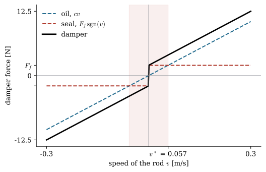
Figure 9.17.5 plots the two parts against the speed. The friction is the larger of the two below the crossover speed
\[
v^* = \frac{F_f}{c}
\tag{9.17.13}\]
and below it the damper behaves as a friction brake. Most of the motion of a suspension is slow, the body rolling and pitching at a few centimetres per second, so \(v^*\) should lie below that.
Code
c_ill, Ff_ill =35.0, 2.0# N s/m and N, for illustrationv = np.linspace(-0.3, 0.3, 601)fig, ax = plt.subplots(figsize=(6, 3.8))ax.plot(v, c_ill*v, color=BLUE, lw=1.5, ls='--', label='oil, $cv$')ax.plot(v, Ff_ill*np.sign(v), color=RED, lw=1.5, ls='--', label=r'seal, $F_f\,\mathrm{sgn}(v)$')ax.plot(v, c_ill*v + Ff_ill*np.sign(v), color='k', lw=2, label='damper')v_x = Ff_ill/c_illax.axvspan(-v_x, v_x, color=RED, alpha=0.08)ax.axhline(0, color=GREY, lw=0.6)ax.axvline(0, color=GREY, lw=0.6)ax.set_xticks([-0.3, v_x, 0.3], ['-0.3', f'$v^*$ = {v_x:.3f}', '0.3'])ax.set_yticks([-12.5, -Ff_ill, 0, Ff_ill, 12.5], ['-12.5', '', '0', r'$F_f$', '12.5'])ax.set_xlabel('speed of the rod $v$ [m/s]')ax.set_ylabel('damper force [N]')ax.legend(frameon=False, loc='upper left')for sp_ in ('top', 'right'): ax.spines[sp_].set_visible(False)plt.show()
Figure 9.17.5: The force of a damper with \(c = 35\) N s/m and a seal friction of \(2\) N against the speed of the rod. Inside the shaded band the friction is the larger part.
At rest the seal holds any force up to its break-out friction \(F_s\), larger than the running friction: up to three times for a \(70\) Shore A O-ring that has stood still a while [6]. A car set down on its wheels therefore stops anywhere within a band around the height its springs would give it. At the shock the spring force may differ from the static force by \(\pm F_s\) before the rod moves, a compression of \(\pm F_s/k\), and at the wheel the band is
\[
\Delta z = \pm\frac{F_s}{k\,\mathrm{MR}}
\tag{9.17.14}\]
The same holds after a bump. A viscous damper takes the same fraction of the swing on each cycle and brings the body back to its static height. Friction takes the same amount, \(4F_f/k\) of amplitude per cycle, and leaves the body standing wherever the swing ends inside the band. Between the two lies the jerky motion called stick-slip, where the rod sticks, the force builds up to \(F_s\), the rod breaks free and runs until it sticks again; Parker advises against moving O-ring seals at speeds below one foot per minute, about \(5\) mm/s, for this reason [6]. A suspension that settles at a different height every time it is pushed down, and feels notchy when pushed slowly, has a damper whose friction is too large.
Seals
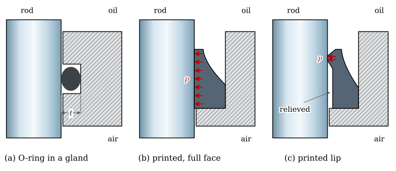
The cap and the body are sealed by static seals, which see no motion and may be squeezed hard. The seal on the rod is dynamic. It must hold the oil while the rod slides through it, and its friction is the \(F_f\) of 9.17.12. Figure 9.17.6 shows the three kinds met in printed dampers.
Figure 9.17.6: Three rod seals in half section, oil above and air below. (a) A bought O-ring of cord \(w\) in a gland of depth \(t\). (b) A printed TPU seal that presses on the rod along its whole bore. (c) A printed lip that touches the rod only at its edge, the bore behind it relieved.
The O-ring in its gland
An O-ring of cord \(w\) fitted in a gland of depth \(t\), Figure 9.17.6 (a), is pressed flat by the squeezesv. kompression\(\varepsilon = (w - t)/w\). According to [6] a dynamic seal should be squeezed by at most about \(16\,\%\), small cords up to \(25\,\%\), and a static seal up to \(30\,\%\). The ring must also have room to change shape: the gland should be filled to between \(60\) and \(85\,\%\) of its volume by the ring, never above \(90\,\%\), since rubber is nearly incompressible and a ring that fills its gland cannot deform.
The squeeze presses the ring onto the rod with a force per unit length of circumference that grows faster than the squeeze. An empirical fit gives it as
\[
N' = E\,w\left(1.25\,\varepsilon^{3/2} + 50\,\varepsilon^6\right)
\tag{9.17.15}\]
where \(E\) is the modulus of the rubber, about \(5.5\) MPa for a \(70\) Shore A nitrile (NBR) ring. The friction on a rod of diameter \(d\) is then
\[
F_f = \mu_s\,N'\,\pi d
\tag{9.17.16}\]
Parker’s handbook gives the running friction of a \(70\) Shore A ring squeezed by \(10\,\%\) as \(0.7\) lb per inch of rubbing length, \(0.12\) N/mm [6], and 9.17.15 matches it with \(\mu_s = 0.16\), the value we use below. The friction coefficient is a fitted number, and the handbook stresses that squeeze, hardness, surface finish and lubrication matter more than any coefficient. An O-ring of \(1.5\) mm cord on a rod of \(5\) mm gives \(0.8\) N at \(10\,\%\), \(1.7\) N at \(16\,\%\) and \(3.5\) N at \(25\,\%\) squeeze. A printed gland makes the squeeze uncertain: a gland bore printed \(0.1\) mm under size on the diameter deepens the squeeze of a \(1.5\) mm cord by over three percentage points, and printed holes typically come out \(0.1\) to \(0.2\) mm small.
Printed seals
A seal printed from TPU, Figure 9.17.6 (b), is harder than an O-ring. TPU \(95\)A has a modulus that data sheets give from about \(10\) to \(60\) MPa depending on the test; we take \(30\) MPa, five to six times that of NBR, so at the same squeeze it presses five to six times harder. The common printed seal also presses along its whole bore. Pushed onto a rod of diameter \(d\) with a radial interference \(\delta\), a ring of wall thickness \(t\) is stretched round its circumference by the strain \(\delta/r\), with \(r = d/2\), and the hoop stress \(E\delta/r\) in its wall pulls it onto the rod with the contact pressure \(p = E t \delta/r^2\), the thin-ring result of a shrink fit. Over a contact length \(b\) this gives the friction
A base \(1.5\) mm thick, pressed on by \(0.1\) mm along \(3\) mm of the rod, gives \(F_f \approx 5.4\) N, and the interference is a printed tolerance: at \(0.2\) mm the friction doubles. Every factor in 9.17.17 is in the hands of the designer except \(E\). A lip, Figure 9.17.6 (c), keeps \(t\) small where it touches, its contact short and its interference small, and leaves a relieved bore behind the edge so that only the lip touches. A lip \(0.6\) mm thick at its edge, touching along \(0.8\) mm with \(0.1\) mm of interference, gives \(0.6\) N, a ninth of the full-face seal. The thin wall of the lip also bends more and makes the seal forgiving of the scatter in \(\delta\).
The concave side of a lip seal faces the oil, so that the oil pressure presses the lip onto the rod as it rises and the seal tightens when it must. The same pressure adds friction while it lasts. A printed seal also needs the room an O-ring needs. A seal that fills its pocket, back and sides, cannot bulge as it is squeezed and becomes nearly rigid.
A seal works on the rod’s surface as much as on its own. The handbook recommends a roughness \(R_a\) of \(0.25\) to \(0.5\) µm for a rod under a moving O-ring, and warns against a mirror finish, wiped dry by the seal, as much as against a rough one that wears it [6]. Nitrile O-rings resist mineral oil and are the usual choice with silicone shock oil too. Rings of EPDM, common in plumbing, do not tolerate mineral oil and are the wrong choice for a damper filled with baby oil [6].
Room for the rod
The rod of diameter \(d\) entering by the stroke \(s\) displaces \(\Delta V = \pi d^2 s/4\) of oil into the air space of volume \(V_0\), and the air pressure rises above atmospheric by
\[
\Delta p = p_0\,\frac{\Delta V}{V_0 - \Delta V}
\tag{9.17.18}\]
with \(p_0\) the atmospheric pressure. The pressure pushes the rod out with the force \(\Delta p\,\pi d^2/4\), a stiff extra spring near the end of the stroke, and presses the seal harder onto the rod. An M5 rod moving \(15\) mm displaces \(295\) mm\(^3\). An air space of three times that raises the pressure by \(0.5\) bar and pushes the rod out with \(1\) N, and an air space barely larger than \(\Delta V\) locks the damper before it reaches the end of its stroke.
Example 2: Why a printed damper bites
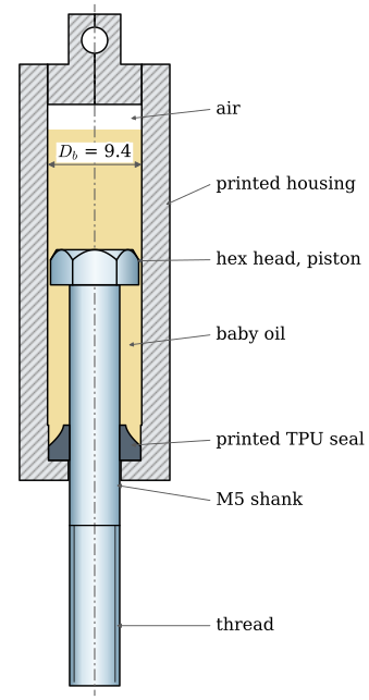
A common printed damper uses an M5 hex bolt as its rod, Figure 9.17.7: the head runs inside a printed bore as the piston, the shank leaves through a printed TPU seal of the full-face kind, and the body is filled with baby oil. It holds its oil, but pushed down by hand it feels sticky, and the car stops at a different height every time. We find the damping and the friction of one such damper on the corner of Example 1, with the inputs of Table 9.17.2.
Figure 9.17.7: Example 2. A printed damper on an M5 \(\times\) 40 hex bolt at mid stroke. The head is the piston, the printed TPU seal at the bottom presses on the shank along its bore.
The gap around the hex head varies from almost nothing at the corners to \(0.7\) mm at the middle of each flat. We sum \(h^3\) around the bore, 9.17.5, take the bore area as the piston area and find \(c\) from 9.17.6. The friction of the seal follows from 9.17.17, and the corner of Example 1 gives the damping ratio, the crossover speed and the band at the wheel.
Code
mu_b =840*24e-6# baby oil, mu = rho*nu, Pa sD_b, s_hx, e_hx, k_hx =9.4e-3, 8.0e-3, 8.8e-3, 3.5e-3A_b = np.pi*D_b**2/4# piston area: the head fills the boreth = np.linspace(0, 2*np.pi, 3600, endpoint=False)a = (th + np.pi/6) % (np.pi/3) - np.pi/6# angle from the normal of the nearest flatr_hx = np.minimum(s_hx/2/np.cos(a), e_hx/2) # the head's outline, corners rounded at e/2h = D_b/2- r_hx # the gap all roundkappa_hx = np.sum(h**3)*(D_b/2)*(th[1] - th[0])/(12*k_hx) # @eq-damper-kappa-gapc_hx = mu_b*A_b**2/kappa_hx # @eq-damper-cE_tpu, t_s, b_s, dl_s, mu_s, d_r =30e6, 1.5e-3, 3e-3, 0.1e-3, 0.16, 5e-3Ff_2 =4*np.pi*mu_s*E_tpu*t_s*dl_s*b_s/d_r # @eq-lip-friction, Nzeta_2 = zeta*c_hx/c_req # zeta is proportional to cv_x2 = Ff_2/c_hx # @eq-damper-crossoverband_2 = Ff_2/(k_s*MR) # @eq-damper-band with F_s = F_f, mm
The damping coefficient against the \(34.9\) N s/m the corner needs, the damping ratio it gives, the seal friction, the crossover speed and the band at the wheel are
The oil passes the head with almost no resistance. The damper gives \(2\,\%\) of the damping the corner needs, and its seal friction is larger than the damping force at any speed the car reaches: \(v^*\) is several metres per second. This damper is a friction brake with oil in it. With the break-out friction the band at the wheel grows further, so the car stands anywhere within about a centimetre of its intended height, and nothing returns it.
Another fault hides in the geometry. In the proportions of Figure 9.17.7 the head rises \(7.5\) mm above mid stroke at full compression, and the shank of the M5 \(\times\) 40 is only \(24\) mm long, so the first millimetre of thread enters the seal and scores it. A socket head, round with \(8.5\) mm, would close the crescents, but in a printed bore of \(9.0\) mm its gap of about \(0.25\) mm is a printed tolerance. The range of \(c\) that a bore between \(8.8\) and \(9.0\) mm and a head between \(8.28\) and \(8.5\) mm give, centred or touching the bore on one side, is
Code
c_sock = []for D in (8.8e-3, 9.0e-3):for d_k in (8.28e-3, 8.5e-3): h0 = (D - d_k)/2for eps in (0.0, 1.0): kap = np.pi*d_k*h0**3*(1+1.5*eps**2)/(12*5e-3) # @eq-damper-kappa-gap, head 5 mm c_sock.append(mu_b*(np.pi*D**2/4)**2/kap)
a factor of thirty, decided by the printer. To reach \(c = 34.9\) N s/m with baby oil and a gap alone, the gap would have to be about \(0.17\) mm all round, held to a few hundredths. With baby oil a printed gap cannot set the damping, and holes must.
Example 3: A printed damper that damps
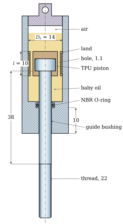
We redesign the damper of Example 2 for the same corner and keep the baby oil, Figure 9.17.8. The bore grows to \(14\) mm, and the rod becomes an ISO 4762 socket screw M5 \(\times\) 60, whose \(38\) mm of plain shank keeps the thread out of the bushing over the full stroke. A piston printed in TPU, \(10\) mm long, is stretched over the round head and holds it without glue. It touches the bore with two thin lands, one at each end, and stands \(0.4\) mm clear of it between them, so the oil passes through four holes printed beside the head and nowhere else. A guide bushing \(10\) mm long carries the side loads, and a single bought NBR O-ring of \(1.5\) mm cord at \(12\,\%\) squeeze seals the rod.
NoteThe recipe
Choose the piston length \(l\) and the number of holes \(n\) so that \(v_q\), 9.17.9, lies above the slow motions of the body. 9.17.7 solved for the diameter with the estimated viscosity, \(d = \left(128\mu l A_p^2/(\pi n c)\right)^{1/4}\), then gives the holes. Print them a little small and open them with a drill turned by hand. Measure \(c\) with the test of Example 4, and since \(c \propto d^{-4}\), open the holes to \(d\,(c_\text{meas}/c)^{1/4}\).
Figure 9.17.8: Example 3. The redesigned damper cut through two of its four holes: a TPU piston stretched over the head of an M5 \(\times\) 60 socket screw and touching the bore at two lands, a bought O-ring in its gland and a guide bushing below it.
Code
D_3, l_3, n_3 =14e-3, 10e-3, 4# bore and piston length (m), number of holesA_3 = np.pi*D_3**2/4rho_b, K_h =840, 1.5# baby oil, kg/m^3; loss coefficient of a holevq_3 =16*np.pi*mu_b*l_3*n_3/(K_h*rho_b*A_3) # @eq-damper-vq: the hole diameter has cancelledd_req = (128*mu_b*l_3*A_3**2/(np.pi*n_3*c_req))**0.25# @eq-damper-holes solved for d, m
The speed up to which the damper stays nearly linear, and the hole diameter that gives the corner its damping, are
The body moves at a few centimetres per second, well below \(v_q\). We print the holes for \(1.1\) mm. The damping coefficient and the quadratic coefficient follow from 9.17.7 and 9.17.8, with the Reynolds number in the holes at a piston speed of \(0.2\) m/s. The friction is that of the O-ring, from 9.17.15 and 9.17.16, and of the two lands, from 9.17.17, each \(0.8\) mm thick and \(0.8\) mm long and pressed on by \(0.05\) mm. The crossover speed and the band at the wheel follow:
\[ \begin{aligned}c &=33.2~\text{N\,s/m},\quad \zeta =0.476\\ c_2 &=159.0~\text{N\,s}^2\text{/m}^2,\quad Re =371.0\\ F_f &=1.08+0.276=1.36~\text{N}\\ v^* &=0.0408~\text{m/s},\quad \Delta z = \pm2.56~\text{mm}\end{aligned} \]
The damping ratio lies in the range we want, and the flow in the holes is laminar. At \(0.2\) m/s, near \(v_q\), the losses at the hole ends double the force, so a sharp bump meets a harder damper than a slow push. The friction has dropped to a quarter of that in Example 2 and the damping has grown about forty times, so the crossover speed has fallen from metres per second to \(4\) cm/s and the band at the wheel to \(\pm 2.6\) mm, more with the break-out friction of an O-ring that has stood.
The lands are thin because a TPU piston that presses on the bore along its whole length, backed by the steel head, is the full-face seal of Example 2 on the largest diameter of the damper: with \(0.1\) mm of interference along \(10\) mm and a wall of \(2.75\) mm, 9.17.17 gives \(12\) N. The lands may also stand off the bore without much harm. Printed \(0.1\) mm under the bore on the diameter, they leave a gap that carries \(2\,\%\) of the flow, and \(0.2\) mm under, \(14\,\%\).
The viscosity is the weak input. Between \(0.012\) and \(0.040\) Pa s the same holes give \(c\) from \(20\) to \(66\) N s/m, a damping ratio from \(0.28\) to \(0.94\); the test of Example 4 finds it and the drill corrects it. A printed gland scatters the squeeze of the O-ring as well. Printed \(0.1\) mm small on the diameter it squeezes the ring by \(15\,\%\) and its friction rises to \(1.5\) N; printed \(0.1\) mm large, \(9\,\%\) and \(0.7\) N. Problem 3 follows this through.
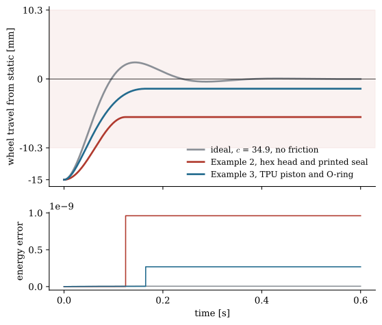
Figure 9.17.9 shows what the change means for the car. The corner is pushed down \(15\) mm at the wheel and let go, with the damper of Example 2, with this one, and with an ideal damper of \(c = 34.9\) N s/m and no friction. We integrate \(m\ddot z = -k_w z - c_w \dot z - c_{2,w}\dot z|\dot z| - F_{f,w}\,\mathrm{sgn}(\dot z)\) at the wheel, with \(k_w\) and \(c_w\) from 9.17.10, and by the same virtual work \(c_{2,w} = c_2\,\mathrm{MR}^3\) and the friction at the wheel \(F_{f,w} = F_f\,\mathrm{MR}\). Whenever the body comes to rest, it stays there if the spring force at the wheel is smaller than \(F_{f,w}\). The energy the spring and the mass lose must equal the work done by the damper and the seal, and the lower panel checks it, as in Work, energy and power.
Code
def drop(c, Ff, c2=0.0, z0=-15e-3, T=0.6):"""Wheel coordinate z from static, released from z0 at rest; c, c2 and Ff at the shock.""" kw, cw, c2w, Fw = k_s*1000*MR**2, c*MR**2, c2*MR**3, Ff*MR t0, y =0.0, np.array([z0, 0.0, 0.0]) # z, z', work done by damper and seal ts, ys = [t0], [y]while t0 < T:ifabs(kw*y[0]) <= Fw: # at rest, the seal holds the spring ts.append(T); ys.append(y)break sgn =-np.sign(y[0]) # it moves towards the static height rhs =lambda t, q: [q[1], (-kw*q[0] - cw*q[1] - c2w*q[1]*abs(q[1]) - Fw*sgn)/m_c, cw*q[1]**2+ c2w*abs(q[1])**3+ Fw*abs(q[1])] stop =lambda t, q: q[1] ifabs(t - t0) >1e-9else sgn stop.terminal, stop.direction =True, -sgn sol = solve_ivp(rhs, (t0, T), y, events=stop, max_step=1e-3, rtol=1e-10, atol=1e-12) ts.extend(sol.t[1:]); ys.extend(sol.y.T[1:]) t0, y = sol.t[-1], sol.y[:, -1].copy() y[1] =0.0 ts, ys = np.array(ts), np.array(ys) E =0.5*m_c*ys[:, 1]**2+0.5*kw*ys[:, 0]**2return ts, ys[:, 0]*1000, (E[0] - E - ys[:, 2])/E[0]cases = [(c_req, 0.0, 0.0, 'ideal, $c$ = 34.9, no friction', GREY, '-'), (c_hx, Ff_2, 0.0, 'Example 2, hex head and printed seal', RED, '-'), (c_3, Ff_3, c2_3, 'Example 3, TPU piston and O-ring', BLUE, '-')]fig, (ax1, ax2) = plt.subplots(2, 1, figsize=(6.4, 5.6), sharex=True, gridspec_kw=dict(height_ratios=[3, 1.3]))for c, Ff, c2, lab, col, ls in cases: t, z, err = drop(c, Ff, c2) ax1.plot(t, z, color=col, lw=2, ls=ls, label=lab) ax2.plot(t, err, color=col, lw=1.2)ax1.axhspan(-band_2, band_2, color=RED, alpha=0.07)ax1.axhline(0, color='k', lw=0.6)ax1.set_ylabel('wheel travel from static [mm]')ax1.set_yticks([-15, -band_2, 0, band_2], ['-15', f'{-band_2:.1f}', '0', f'{band_2:.1f}'])ax1.set_ylim(-16, band_2 +0.5)ax1.legend(frameon=False, loc='lower right', fontsize=9)ax2.set_ylabel('energy error')ax2.set_xlabel('time [s]')ax2.set_xticks([0, 0.2, 0.4, 0.6])ax2.ticklabel_format(axis='y', style='sci', scilimits=(0, 0))for a_ in (ax1, ax2):for sp_ in ('top', 'right'): a_.spines[sp_].set_visible(False)plt.show()
Figure 9.17.9: Example 3. The corner pushed down \(15\) mm and released. The damper of Example 2 rises once and sticks inside its band (shaded); the redesign settles like the ideal damper, a little short of the static height. Lower panel: the energy lost by the mass and the spring minus the work done by damper and seal, relative to the initial energy.
The ideal damper returns the body in about a quarter of a second with one small overshoot. The redesign comes to rest after \(0.16\) s without overshooting, \(1.5\) mm short of the static height: the losses at the hole ends brake the fast start of the swing, and the friction holds the slow end of it. The damper of Example 2 rises only part of the way and sticks \(5.7\) mm below the static height, since its friction at the wheel takes most of what the spring pushes with. Pushed up instead, it would stick as far above. The energy error stays at the level of the integrator’s tolerance, so the curves show the model and not integration error.
Designing a damper for the printer
The rod. A bolt makes a good rod if only its smooth shank passes the seal. Longer socket screws to ISO 4762 have a plain shank, with \(22\) mm of thread in size M5, and so do hex bolts to ISO 4014; bolts to ISO 4017 are threaded to the head and cannot be used. The shank must cover the stroke plus the length of the seal and of the bushing, so that the thread stays outside both at full compression. A shank is somewhat under its nominal diameter, and a zinc-plated surface is rough, so we measure its diameter with a micrometer, size the gland from the measured value, and polish the shank with fine abrasive paper while it turns in a drill. A ground steel rod of \(5\) mm, sold for linear bearings, is a better rod where its end can be fixed to the piston.
The piston. The piston must close the bore except for the passages we chose. A hex head leaves crescents that pass the oil freely, and a round head leaves a gap that the printer sets. A piston printed in TPU stretches over the head and holds it, and it can touch the bore, so that its holes carry all the flow. It touches at two thin lands, one at each end, and stands clear of the bore between them, for the reason given in Example 3. The holes run beside the head, as long as the piston, and their number and length are chosen for \(v_q\), 9.17.9. Printed with the axis vertical they come out undersize and rough, so they are printed small and opened with a drill turned by hand to the size the test asks for. A piston prints in minutes, and a set with different holes is the quickest way to tune a damper.
The guide. The seal cannot also be the bearing. A rod guided only by its seal tilts under any side load, presses the seal harder on one side and binds. A bushing at least twice as long as the rod diameter, drilled or reamed to size after printing, carries the side loads, and the mounts at both ends are pins or ball joints, so that the damper carries force only along its axis.
The seal. A bought NBR O-ring is the first choice for the rod, squeezed by \(10\) to \(15\,\%\) in a gland that leaves room around it. Since a printed gland scatters by a tenth of a millimetre, a short test print with a row of glands of different bores, in steps of \(0.1\) mm on one rod, finds the one that seals without gripping. A printed TPU seal works as a lip: thin at the edge, touching only there, the bore behind it relieved, the concave side towards the oil and room behind it to deflect. It is printed with its axis vertical, so that each layer is a complete ring, with the seam of the layers placed away from the lip edge. One seal at the right squeeze holds the oil; a second ring doubles the friction. A seal of either kind is greased on assembly, and silicone grease suits NBR and baby oil.
The housing. The bore is printed with its axis vertical, which keeps it round, and the lands of the piston run on its layer lines, which a fine layer height keeps smooth. The walls must be tight: several perimeters, good layer bonding and a tested print keep the oil from weeping through.
The oil and the filling. Baby oil is safe to handle and its viscosity is uncertain, so the holes are tuned to the oil, with the recipe of Example 3 and the test of Example 4. The body is filled slowly with the piston at the bottom, the rod is worked a few times to drive out bubbles, and the oil is topped up to leave the air space of 9.17.18. Air left in the oil makes the damper spongy: it travels a little with no force at each reversal.
Table 9.17.3 lists the faults of a printed damper by what they feel like.
Table 9.17.3: Faults of a printed damper.
symptom
cause
remedy
sticky, notchy when pushed slowly, settles at different heights
seal friction large against damping
lip seal or one O-ring at \(10\) to \(15\,\%\) squeeze, more damping from the holes
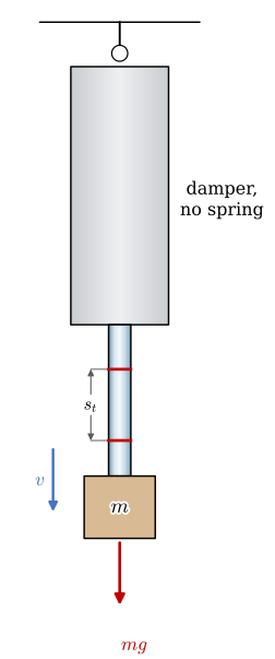
The force of the damper, 9.17.12 with the quadratic term of 9.17.8, has three unknowns, \(F_f\), \(c\) and \(c_2\), and a test with weights finds all three. The damper, without its spring, hangs from a pin with its rod down, Figure 9.17.10, and the air space is vented so that its pressure does not act on the rod. A mass \(m\) hung on the rod pulls it out. After a short start the rod moves at a steady speed \(v\), at which the weight is carried by the damper, \(mg = F_f + cv + c_2v^2\). Two tape marks \(s_t = 20\) mm apart on the rod and a phone filming at \(240\) frames per second give the speed, \(v = s_t/(N/240)\), from the number of frames \(N\) the rod takes between the marks. The mass includes the rod and the hook. A parabola through the points \((v, mg)\) meets the force axis at \(F_f\) with the slope \(c\), and its curvature gives \(c_2\). The smallest mass that starts the rod at all measures the break-out friction.
Figure 9.17.10: Example 4. The drop test. The weight \(mg\) of the mass on the rod is carried by the damper once the rod moves at its steady speed \(v\), timed between two marks a distance \(s_t\) apart.
The readings of Table 9.17.4 are invented for the damper of Example 3 to show the evaluation.
Table 9.17.4: Example 4. Readings of the drop test.
mass [kg]
\(0.20\)
\(0.25\)
\(0.40\)
\(0.60\)
\(0.80\)
\(1.00\)
\(1.30\)
frames between the marks
does not move
\(182\)
\(90\)
\(58\)
\(44\)
\(36\)
\(29\)
Code
m_t = np.array([0.25, 0.40, 0.60, 0.80, 1.00, 1.30]) # kg, rod and hook includedN_t = np.array([182, 90, 58, 44, 36, 29]) # frames between the marksv_t =0.020/(N_t/240) # m/sF_t = m_t*9.81c2_fit, c_fit, Ff_fit = np.polyfit(v_t, F_t, 2) # mg = F_f + c v + c2 v^2Fs_lo, Fs_hi =0.20*9.81, 0.25*9.81# break-out between these two weightsmu_fit = mu_b*c_fit/c_3 # c is proportional to mud_new = d_3*(c_fit/c_req)**0.25# c is proportional to d^-4
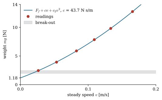
Figure 9.17.11 plots the readings. The fitted damping coefficient, quadratic coefficient and running friction, the bounds on the break-out friction, the viscosity that the measured \(c\) implies, and the hole diameter that brings \(c\) to the \(34.9\) N s/m of the corner are
\[ \begin{aligned}c &=43.6~\text{N\,s/m},\quad c_2 =159.0~\text{N\,s}^2\text{/m}^2,\quad F_f =1.18~\text{N}\\ F_s &= 1.96\text{ to }2.45~\text{N},\quad \mu =0.0265~\text{Pa\,s},\quad d = 1.1\left(\frac{c}{34.9}\right)^{1/4} =1.16~\text{mm}\end{aligned} \]
Figure 9.17.11: Example 4. The weight against the steady speed of the rod. The curve leaves the force axis at the running friction with the slope \(c\) and bends upward with the losses at the hole ends; the grey band lies between the heaviest mass that did not start the rod and the lightest that did.
The test returns a damping coefficient above the \(33\) N s/m that Example 3 predicted: the oil is thicker than our estimate. Its quadratic coefficient agrees with the prediction, since \(c_2\) does not depend on the viscosity. Opening the four holes from \(1.1\) to \(1.15\) mm, the nearest drill, brings \(c\) down to about \(36.5\) N s/m, close to the \(34.9\) the corner needs. The running friction is near \(1.2\) N, with a break-out friction about twice that. Run on the damper of Example 2, the same test ends after the first reading: a mass that overcomes the seal’s \(5\) N drops the rod almost freely, since there is too little damping to measure. A damper whose curve passes this test with an intercept of a newton or so and a slope near its design value is ready for the car.
TipIn industry: damper dynamometers and rod seals
Dampers are measured on a damper dynamometer, which strokes the damper over a range of speeds and plots its force against its velocity, and a car’s damping is tuned on that curve and on the road [1]. The rod seals of production dampers are seldom plain O-rings. They are lip seals of polyurethane or PTFE, often with a separate wiper outside them, chosen for low and steady friction and long life [1].
Problems
Problem 1: The rear corner. The rear of the car of Example 1 is heavier, \(m = 0.65\) kg per corner, with the same motion ratio, ride frequency and damping ratio. What spring rate and damping coefficient does the rear shock need, and how do you get the damping with the piston of Example 1?
Answer:Both scale with the mass: \(k = 0.877 \cdot 1.3 = 1.14\) N/mm and \(c = 34.9 \cdot 1.3 = 45.4\) N s/m. The static sag at the wheel stays \(15.5\) mm, by 9.17.11. Two holes of \(1.1\) mm give \(44\) N s/m in the same oil, or the \(1.2\) mm holes stay and the oil is thickened in proportion, to about \(350 \cdot 45.4/30.9 \approx 510\) cSt.
Problem 2: A socket head in a printed bore. An M5 socket head of \(8.5\) mm runs \(5\) mm long in a bore of \(9.0\) mm as the piston of a damper filled with baby oil, \(\mu = 0.021\) Pa s, Figure 9.17.3 (b). What is its damping coefficient centred and touching the bore? Within what limits must the bore be printed to keep the centred value within \(\pm 25\,\%\)?
Answer:9.17.5 gives \(\kappa = \pi \cdot 8.5 \cdot 0.25^3/(12 \cdot 5)
= 6.95 \cdot 10^{-3}\) mm\(^3\) and 9.17.6\(c = 12.1\) N s/m, falling to \(4.8\) N s/m with the piston against the bore. Since \(c \propto h^{-3}\), \(\pm 25\,\%\) allows \(h\) to change by the factors \(1.25^{-1/3} = 0.93\) and \(0.75^{-1/3} = 1.10\), so \(0.232 \le h \le 0.275\) mm and \(8.96 \le D_b \le 9.05\) mm: a few hundredths, finer than a printer holds.
Problem 3: The squeeze of a printed gland. A shank measured to \(4.95\) mm runs in an O-ring of \(1.5\) mm cord, Figure 9.17.6 (a), in a printed gland whose bore is drawn for \(12\,\%\) squeeze. What bore is drawn, and what squeeze and friction result if it prints \(0.1\) mm small, \(0.1\) mm large or \(0.2\) mm small? Use \(E = 5.5\) MPa and \(\mu_s = 0.16\).
Answer:The gland depth for \(12\,\%\) is \(t = 0.88 \cdot 1.5 = 1.32\) mm, so the bore is drawn \(4.95 + 2 \cdot 1.32 = 7.59\) mm. Each \(0.1\) mm on the diameter moves \(t\) by \(0.05\) mm and the squeeze by \(3.3\) points. 9.17.15 and 9.17.16 give \(1.07\) N as drawn, \(1.55\) N at \(15.3\,\%\) (\(0.1\) mm small), \(0.65\) N at \(8.7\,\%\) (\(0.1\) mm large) and \(2.11\) N at \(18.7\,\%\) (\(0.2\) mm small), above the \(16\,\%\) the handbook allows for a moving seal. A row of test glands settles it.
Problem 4: The air space. The damper of Example 3, Figure 9.17.8, has an M5 rod and a stroke of \(15\) mm. How long must the air space under the cap be for the pressure to rise by at most \(0.3\) bar at full compression, and what force does that pressure put on the rod?
Answer:\(\Delta V = \pi \cdot 2.5^2 \cdot 15 = 295\) mm\(^3\). 9.17.18 with \(\Delta p/p_0 = 0.3\) gives \(V_0 = \Delta V(1 + 1/0.3) = 1276\) mm\(^3\), which in the \(14\) mm bore is \(1276/153.9 = 8.3\) mm of air. The pressure pushes the rod out with \(0.3 \cdot 10^5 \cdot 19.6 \cdot 10^{-6} = 0.59\) N, less than half the friction of the seal and the lands.
Further reading
Dixon’s handbook covers the damper as a part, with its valves, oils, seals and the room for the displaced oil [1]. The Parker O-ring handbook gives gland dimensions, squeeze, gland fill, friction and material compatibility for O-ring seals [6]. White derives the laminar flow in pipes and between plates behind 9.17.4 and 9.17.5.
References
[1]
Dixon JC. The shock absorber handbook. 2nd ed. Chichester: John Wiley & Sons; 2007.
[2]
White FM. Fluid mechanics. 8th ed. New York: McGraw-Hill Education; 2016.